Trouble Diagnosis

In this manual: Trouble Diagnosis
How to Use This Manual — 1Precautions — 1Preparation — 1Vehicle Information — 1Basic Inspection — 1Preparation. Commercial Service Tools Or/and Repair Part — 1Description — 1Component Parts — 1System — 1Diagnosis System (vcm) — 1Ecu Diagnosis Information. Vcm — 1Ev Control System — 1Ev/hev (vcm) — 1Component Parts /circuit Diagnosis — 1Ev Control System — 1Periodic Maintenance. Ev System Warning Lamp — 1Removal and Installation. Vcm — 1Traction Motor System :: Front Traction Motor — 1Preparation — 1Description — 4Basic Inspection — 2Dtc Diagnosis — 2Component Parts /circuit Diagnosis — 1Traction Motor System :: Rear Traction Motor — 1Description — 4Basic Inspection — 2Dtc Diagnosis — 2Component Parts /circuit Diagnosis — 1Removal and Installation — 1Ev Battery System :: 66kwh Li-Ion Battery — 1Description — 4Basic Inspection — 2Dtc Diagnosis — 2Component Parts /circuit Diagnosis — 1Removal and Installation — 1Disassembly and Assembly — 2Service Data — 1Ev Battery System :: 91kwh Li-Ion Battery — 1Description — 4Basic Inspection — 2Dtc Diagnosis — 2Component Parts /circuit Diagnosis — 1Removal and Installation — 1Disassembly and Assembly — 1Service Data — 2Preparation. Vehicle Charging System — 1Vehicle Charging System :: Description — 1Component Parts — 2System — 1Diagnosis System (on-Board Charger) — 1Diagnosis System (dc/dc Converter) — 1Ecu Diagnosis Information — 1Vehicle Charging System — 1Charger/pd Module (on-Board Charger) — 1Cplc (cplc) — 1Dcdc (dc/dc Converter) — 1Component Parts/circuit Diagnosis — 1Symptom Diagnosis — 1Evse Inspection — 1Periodic Maintenance — 1Removal and Installation — 1Disassembly and Assembly — 1Preparation. High Voltage Cooling System — 1Description — 1Symptom Diagnosis. Overheating Cause Analysis — 1Periodic Maintenance — 1Coolant — 1Removal and Installation — 1Radiator — 1Service Data — 1Removal and Installation. Accelerator Control System — 1Reduction Gear: Re1f62a — 1Removal and Installation — 1Transaxle & Transmission :: Electric Shift — 1Description — 3Basic Inspection — 2Dtc Diagnosis — 2Component Parts /circuit Diagnosis — 1Removal and Installation — 1Rear Final Drive: Rn1r62a — 1Removal and Installation — 1Preparation. Front Axle System — 1Symptom Diagnosis. Noise, Vibration and Harshness (nvh) Troubleshooting — 1Periodic Maintenance — 1Removal and Installation — 1Service Data. Front Drive Shaft — 12wd — 14wd — 1Periodic Maintenance — 1Removal and Installation — 1Preparation. Front Suspension System — 1Symptom Diagnosis. Noise, Vibration and Harshness (nvh) Troubleshooting — 1Periodic Maintenance — 1Removal and Installation — 1Service Data — 1Symptom Diagnosis. Noise, Vibration and Harshness (nvh) Troubleshooting — 1Periodic Maintenance — 1Removal and Installation — 1Service Data — 1Preparation. Road Wheels & Tires System — 1Description — 1System — 1Ecu Diagnosis Information. Bcm (body Control Module) — 1Tpms — 1Dtc/circuit Diagnosis — 1Symptom Diagnosis — 1Periodic Maintenance. Road Wheels & Tires — 1Removal and Installation — 1Service Data — 1Preparation. Brake System — 1System Description — 1Component Parts — 1Ecu Diagnosis Information. Electrically-Driven Intelligent Brake Unit — 1Basic Inspection — 1Dtc/circuit Diagnosis — 1Symptom Diagnosis — 1Periodic Maintenance — 1Removal and Installation — 1Service Data — 1Preparation. Parking Brake System — 1System Description — 1Component Parts — 1System — 1Ecu Diagnosis Information. Abs Actuator and Electric Unit (control Unit) — 1Basic Inspection. Diagnosis and Repair Work Flow — 1Component Parts /circuit Diagnosis — 1Symptom Diagnosis — 1Removal and Installation — 1Brake Control System :: With Vdc — 1System Description — 3Basic Inspection — 2Dtc/circuit Diagnosis — 1Symptom Diagnosis — 2Removal and Installation — 1Brake Control System :: Automatic Brake Hold — 1System Description — 3Component Parts /circuit Diagnosis — 1Removal and Installation — 1Brake Control System :: E-Step — 1System Description — 3Removal and Installation — 1System Description — 1Ecu Diagnosis Information — 1Basic Inspection — 1Symptom Diagnosis — 1Rear Automatic Braking — 1System Description — 1Basic Inspection — 1Preparation. Steering System — 1System Description — 1Component Parts — 1Basic Inspection — 1Dtc/circuit Diagnosis — 1Symptom Diagnosis — 1Periodic Maintenance. Steering Wheel — 1Removal and Installation — 1Service Data — 1System Description — 1Component Parts — 1Steering Control System — 1Ecu Diagnosis Information. Power Steering Control Module — 1Dtc/circuit Diagnosis — 1Component Parts /circuit Diagnosis — 1Symptom Diagnosis — 1Removal and Installation. Power Steering Control Module — 1System Description — 1Removal and Installation — 1System Description — 1System — 1Basic Inspection. Diagnosis and Repair Work Flow — 1Dtc/circuit Diagnosis — 1Symptom Diagnosis — 1Component Parts — 1Basic Inspection — 1Removal and Installation — 1System Description — 1System — 1Ecu Diagnosis Information. Air Bag Diagnosis Sensor Unit — 1Basic Inspection — 1Dtc/circuit Diagnosis — 1Symptom Diagnosis — 1System Description. Description. Ventilation System — 1Removal and Installation — 1Preparation. Preparation — 1System Description — 1Basic Inspection — 1Symptom Diagnosis — 1Removal and Installation — 1Electric Compressor — 1Cooler Pipe and Hose — 1A/c Unit Assembly Cover — 1A/c Unit Assembly — 1Heater & Air Conditioning Control System :: Automatic Air Conditioning — 1System Description — 1Ecu Diagnosis Information — 1Basic Inspection — 2Dtc Diagnosis — 1Symptom Diagnosis — 1Removal and Installation — 2Preparation. Preparation — 1Symptom Diagnosis. Squeak and Rattle Trouble Diagnoses — 1Removal and Installation — 1Preparation. Instrument Panel — 1Component Parts — 1System — 1Ecu Diagnosis Information. Flexible Center Storage Control Module — 1Basic Inspection. Diagnosis and Repair Work Flow — 1Dtc/circuit Diagnosis — 1Symptom Diagnosis — 1Removal and Installation — 1Preparation. Preparation — 1Component Parts — 1System — 1Ecu Diagnosis Information. Driver Lumbar Support Control Module — 1Basic Inspection. Diagnosis and Repair Work Flow — 1Dtc/circuit Diagnosis — 1Symptom Diagnosis — 1Removal and Installation — 1System Description — 1System — 1Ecu Diagnosis Information — 1Basic Inspection — 1Dtc/circuit Diagnosis — 1Symptom Diagnosis — 1Manual Function Does Not Operate — 1Memory Function Does Not Operate — 1Removal and Installation — 1Preparation. Preparation — 1System Description — 1System (intelligent Key System) — 1Diagnosis System (bcm) — 1Ecu Diagnosis Information — 1Basic Inspection — 1Dtc/circuit Diagnosis — 1U2141-87 Can Comm Circuit — 1Power Supply and Ground Circuit — 1Symptom Diagnosis — 1Automatic Back Door Operation Does Not Operate — 1Back Door Does Not Open — 1Door Does Not Lock/unlock with Door Lock and Unlock Switch — 1Removal and Installation — 1Hood — 1Radiator Core Support — 1Charge Port Lid — 1Front Fender — 1Front Door — 1Rear Door — 1Back Door — 1Hood Lock — 1Front Door Lock — 1Rear Door Lock — 1Back Door Lock — 1Outside Key Antenna — 1System Description — 1System — 1Ecu Diagnosis Information. Inverter (front), Inverter (rear), Bcm, Intelligent Key Unit — 1Basic Inspection — 1Dtc/circuit Diagnosis — 1Symptom Diagnosis — 1Preparation — 1Symptom Diagnosis. Squeak and Rattle Trouble Diagnoses — 1Removal and Installation — 1System Description — 1Ecu Diagnosis Information — 1Basic Inspection — 1Dtc/circuit Diagnosis — 1Power Supply and Ground Circuit — 1Symptom Diagnosis — 1Front Passenger Side Power Window Does Not Operate — 1Rear Lh Side Power Window Does Not Operate — 1Rear Rh Side Power Window Does Not Operate — 1Removal and Installation. Power Window Main Switch — 1Preparation. Preparation — 1System Description — 1Ecu Diagnosis Information — 1Basic Inspection — 1Dtc/circuit Diagnosis — 1Power Supply and Ground Circuit — 1Sunroof Switch Assembly — 1Symptom Diagnosis — 1Auto Operation Does Not Operate — 1Removal and Installation — 1Preparation — 1Description — 1Symptom Diagnosis. Squeak and Rattle Trouble Diagnoses — 1Removal and Installation — 1Service Information — 6Repair Information — 1Precaution — 1Preparation — 1Removal and Installation — 1Service Data — 1Preparation. Preparation — 1Component Parts — 1System — 1Ecu Diagnosis Information — 1Wiring Diagram. Door Mirror — 1Basic Inspection. Diagnosis and Repair Work Flow — 1Dtc/circuit Diagnosis — 1Power Supply and Ground Circuit — 1Symptom Diagnosis — 1Removal and Installation — 1Exterior Lighting System :: Led Headlamp — 1System Description — 3Basic Inspection — 1Dtc/circuit Diagnosis — 1Symptom Diagnosis — 1Periodic Maintenance — 1Removal and Installation — 1System Description — 1System — 1Diagnosis System (bcm) — 1Ecu Diagnosis Information. Bcm, Intelligent Key Unit — 1Basic Inspection. Diagnosis and Repair Work Flow — 1Dtc/circuit Diagnosis — 1Symptom Diagnosis. Interior Lighting System Symptom — 1Removal and Installation — 1Service Data. Bulb Specifications — 1System Description — 1System — 1Ecu Diagnosis Information. Bcm, Ipdm E/r — 1Basic Inspection. Diagnosis and Repair Work Flow — 1Dtc/circuit Diagnosis — 1Symptom Diagnosis — 1Removal and Installation — 1System Description — 1Ecu Diagnosis Information. Bcm — 1Basic Inspection. Diagnosis and Repair Work Flow — 1Dtc/circuit Diagnosis — 1Symptom Diagnosis — 1Removal and Installation — 1Preparation. Preparation — 1Removal and Installation. Horn — 1Preparation. Commercial Service Tools Or/and Repair Part — 1System Description — 1Component Parts — 1Ecu Diagnosis Information. Approaching Vehicle Sound for Pedestrians (vsp) Control Unit — 1Approaching Vehicle Sound for Pedestrians (vsp) — 1Vsp [approaching Vehicle Sound for Pedestrians (vsp) Control Unit] — 1Approaching Vehicle Sound for Pedestrians (vsp) System — 1Removal and Installation — 1Removal and Installation — 1Wireless Charger — 1System Description — 1Basic Inspection — 1Dtc/circuit Diagnosis — 1Removal and Installation — 1Component Parts — 1System — 1Diagnosis System (bcm) — 1Ecu Diagnosis Information. Bcm — 1Basic Inspection — 1Dtc/circuit Diagnosis — 1Symptom Diagnosis — 1Removal and Installation — 1Can Fundamental — 1Description — 1Trouble Diagnosis — 1Can (controller Area Network) — 1Description — 1
~7min read
  • Component Description
  • Condition of Error Detection
  • Symptom When Error Occurs in Can Communication System
  • Can Diagnosis with Consult
  • Self-Diagnosis
  • Network Diagnosis
  • How to Use Can Communication Signal Chart

Component Description Nissan Ariya: FE0

System Description
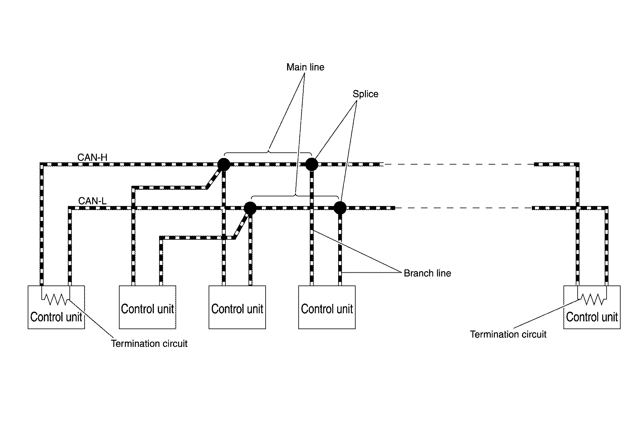
ComponentDescription
Main line CAN communication line between splices
Branch line CAN communication line between splice and a control unit
Splice A point connecting a branch line with a main line
Termination circuit Circuit connected across the CAN communication system. (Resistor)

Condition of Error Detection Nissan Ariya

System Description

DTC (e.g. U1000 and U1001) of CAN communication is indicated on SELF-DIAG RESULTS on CONSULT if a CAN communication signal is not transmitted or received between units for 2 seconds or more.

CAN COMMUNICATION SYSTEM ERROR

  • CAN communication line open (CAN-H, CAN-L, or both)

  • CAN communication line short (ground, between CAN communication lines, other harnesses)

  • Error of CAN communication control circuit of the unit connected to CAN communication line

WHEN DTC OF CAN COMMUNICATION IS INDICATED EVEN THOUGH CAN COMMUNICATION SYSTEM IS NORMAL

  • Removal/installation of parts: Error may be detected when removing and installing CAN communication unit and related parts while turning the power switch ON. (A DTC except for CAN communication may be detected.)

  • Fuse blown out (removed): CAN communication of the unit may cease.

  • Voltage drop: Error may be detected if voltage drops due to discharged battery when turning the power switch ON (Depending on the control unit which carries out CAN communication).

  • Error may be detected if the power supply circuit of the control unit, which carries out CAN communication, malfunctions (Depending on the control unit which carries out CAN communication).

  • Error may be detected if reprogramming is not completed normally.

Symptom When Error Occurs in Can Communication System Nissan Ariya 1st generation

System Description

In CAN communication system, multiple control units mutually transmit and receive signals. Each control unit cannot transmit and receive signals if any error occurs on CAN communication line. Under this condition, multiple control units related to the root cause malfunction or go into fail-safe mode.

ERROR EXAMPLE

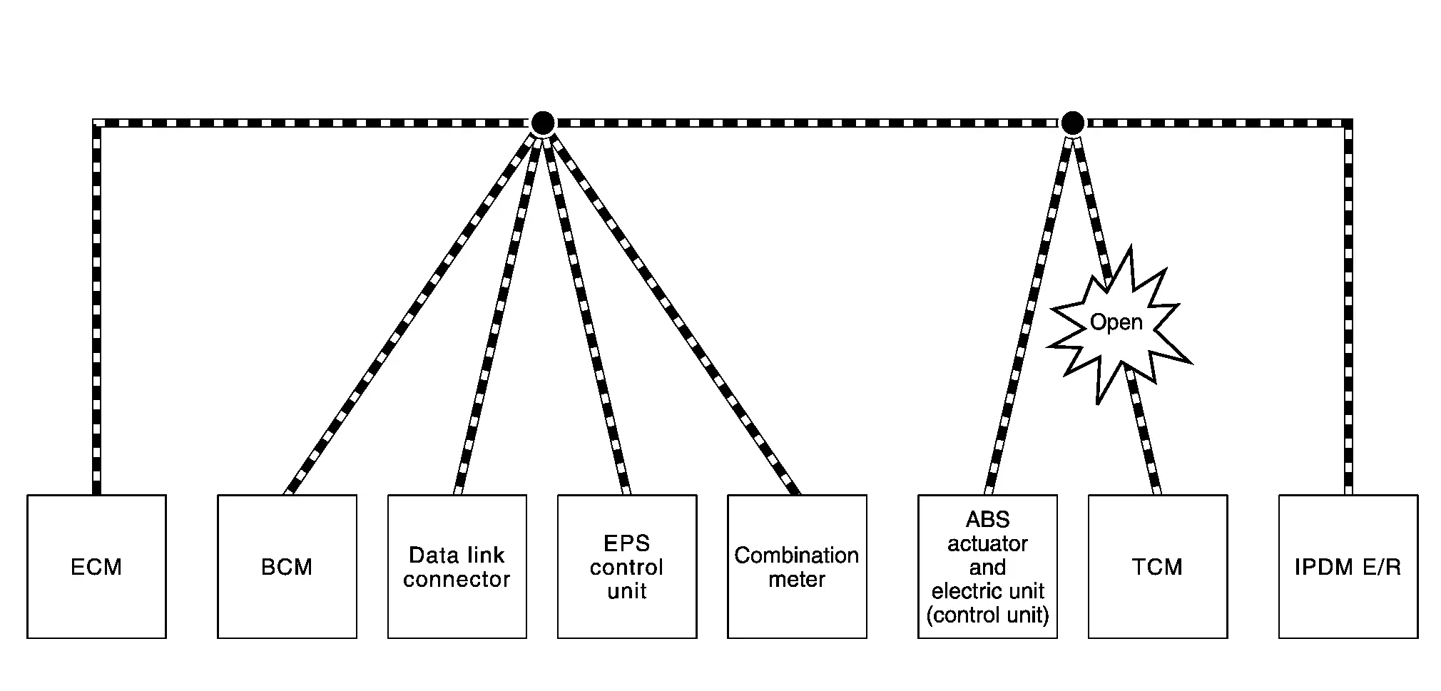
Example: Main Line Between Data Link Connector and ABS Actuator and Electric Unit (Control Unit) Open Circuit

Unit nameMajor symptom
ECM Engine torque limiting is affected, and shift harshness increases.
BCM
  • Reverse warning buzzer does not sound.

  • The front wiper moves under continuous operation mode even though the front wiper switch being in the intermittent position.

EPS control unit The steering effort increases.
Combination meter
  • The shift position indicator and OD OFF indicator turn OFF.

  • The speedometer is inoperative.

  • The odo/trip meter stops.

ABS actuator and electric unit (control unit) Normal operation.
TCM No impact on operation.
IPDM E/R

When the power switch is ON,

  • The headlamps (Lo) turn ON.

  • The cooling fan continues to rotate.

Example: TCM Branch Line Open Circuit

Unit nameMajor symptom
ECM Engine torque limiting is affected, and shift harshness increases.
BCM Reverse warning buzzer does not sound.
EPS control unit Normal operation.
Combination meter
  • Shift position indicator and O/D OFF indicator turn OFF.

  • Warning lamps turn ON.

ABS actuator and electric unit (control unit) Normal operation.
TCM No impact on operation.
IPDM E/R Normal operation.
ErrorDifference of symptom
Data link connector branch line open circuit Normal operation.
CAN-H, CAN-L harness short-circuit Most of the control units which are connected to the CAN communication system enter fail-safe mode or are deactivated.

Example: Data Link Connector Branch Line Open Circuit
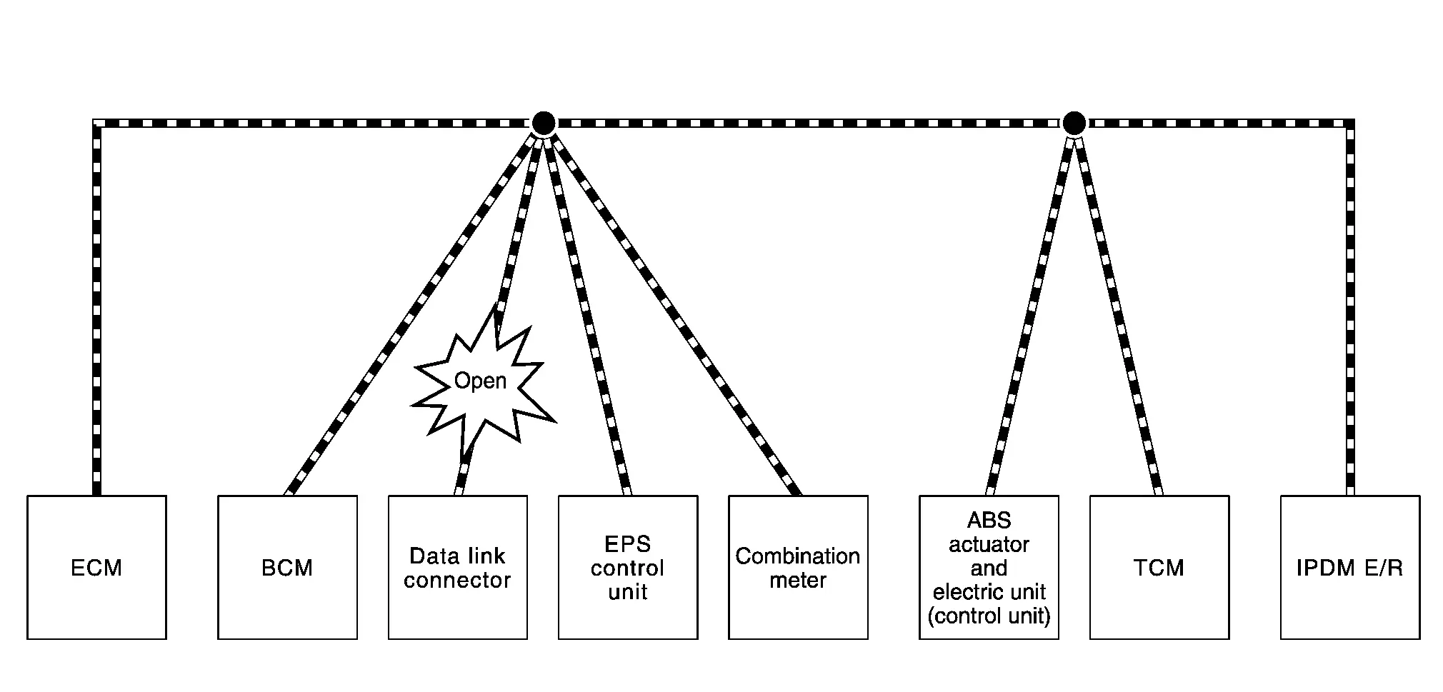
Unit nameMajor symptom
ECM Normal operation.
BCM
EPS control unit
Combination meter
ABS actuator and electric unit (control unit)
TCM
IPDM E/R

Example: CAN-H, CAN-L Harness Short Circuit

Unit nameMajor symptom
ECM
  • Engine torque limiting is affected, and shift harshness increases.

  • Engine speed drops.

BCM
  • Reverse warning buzzer does not sound.

  • The front wiper moves under continuous operation mode even though the front wiper switch being in the intermittent position.

  • The room lamp does not turn ON.

  • The engine does not start (if an error or malfunction occurs while turning the power switch OFF.)

  • The steering lock does not release (if an error or malfunction occurs while turning the power switch OFF.)

EPS control unit The steering effort increases.
Combination meter
  • The tachometer and the speedometer do not move.

  • Warning lamps turn ON.

  • Indicator lamps do not turn ON.

ABS actuator and electric unit (control unit) Normal operation.
TCM No impact on operation.
IPDM E/R

When the power switch is ON,

  • The headlamps (Lo) turn ON.

  • The cooling fan continues to rotate.

Can Diagnosis with Consult Nissan Ariya 1st generation

System Description

CAN diagnosis on CONSULT extracts the root cause by receiving the following information.

  • Response to the system call

  • Control unit diagnosis information

  • Self-diagnosis

  • Network Diagnosis

Self-Diagnosis Nissan Ariya SUV

System Description

If communication signals cannot be transmitted or received among control units communicating via CAN communication line, CAN communication-related DTC is displayed on the CONSULT “Self Diagnostic Result” screen.

Network Diagnosis Nissan Ariya SUV

System Description

When CAN communication error occurs, the estimated malfunction part is displayed in "Network Diagnosis". The malfunction part is identified by referring to the following displays of network and unit, and error cases.

ItemColorDiagnosis result
Network Red background There is an unit where unable communication has occurred.
Red text CAN communication error is occurred. (Present error)
Yellow CAN communication error was occurred. (Past error)
Green No CAN communication error are occurred between the units in the network.
ECU status Red background Unable communication
Red text CAN communication error is detected by other units. (Present error)
Yellow CAN communication error was detected by other units. (Past error)
Green The unit is normal. There is error of CAN communication with some units.
Gray Normal

ERROR EXAMPLE

Example: Unable Communication for Combination Meter

ItemDescription
CONSULT display One unit with a red background
Work procedure Perform trouble diagnosis procedure for combination meter.

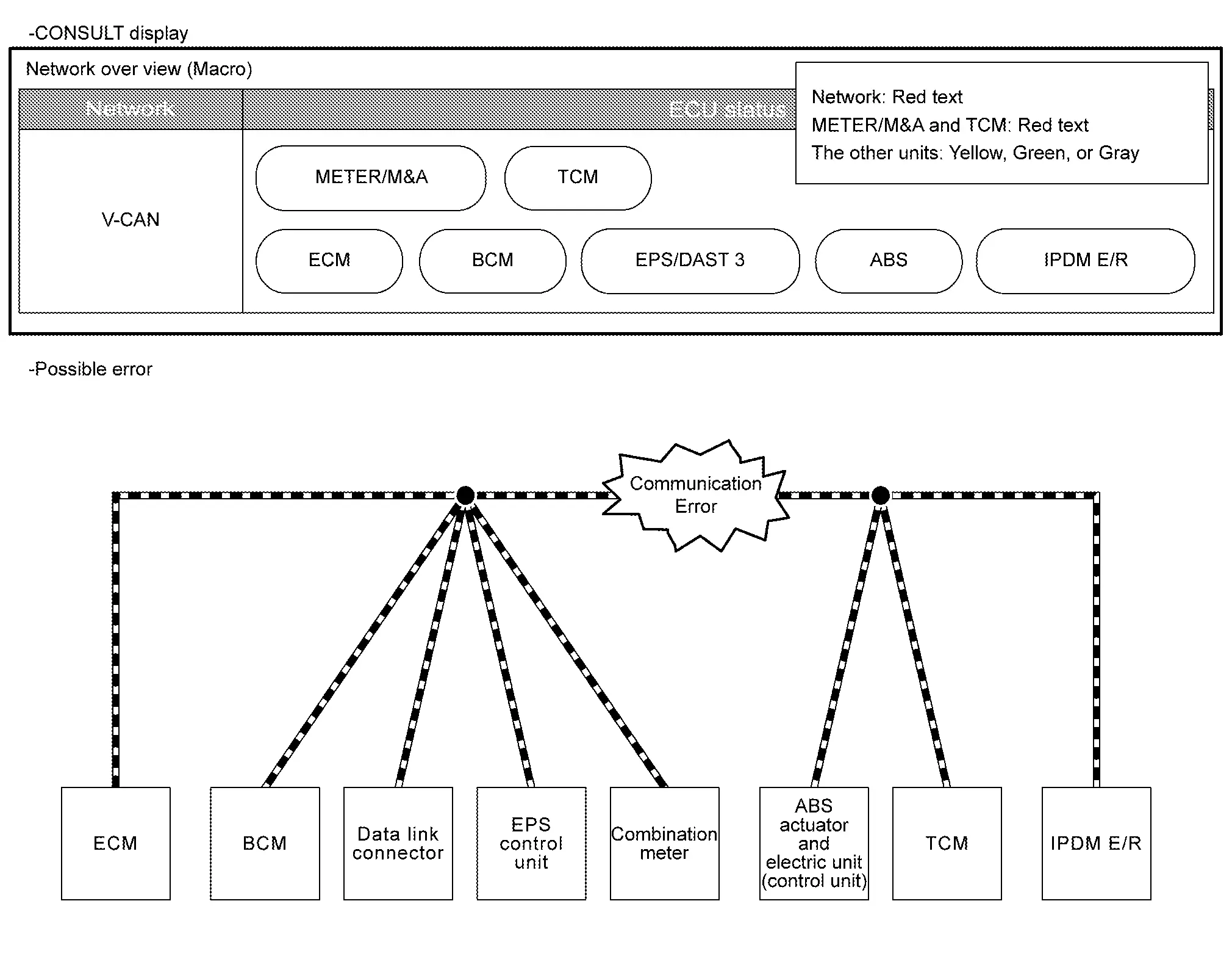
Example: CAN Communication Error for Main Line Between Combination Meter and TCM

ItemDescription
CONSULT display Some units connected to the main line with red text
Work procedure Perform diagnosis procedure for main line between combination meter and TCM.

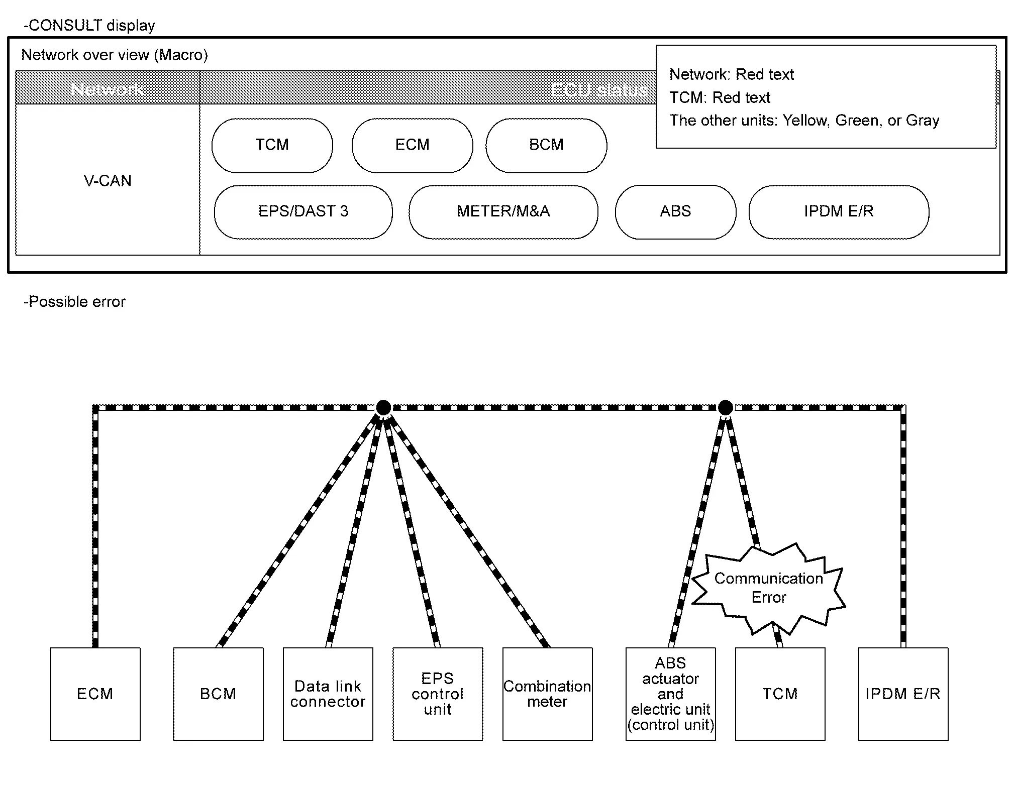
Example: CAN Communication Error for TCM Branch Line

ItemDescription
CONSULT display One unit with a red text
Work procedure Perform diagnosis procedure for TCM branch line.

Example: Unable Communication for Data Link Connector

ItemDescription
CONSULT display All of network and units with red backgrounds
Work procedure Perform diagnosis procedure for data link connector branch line.

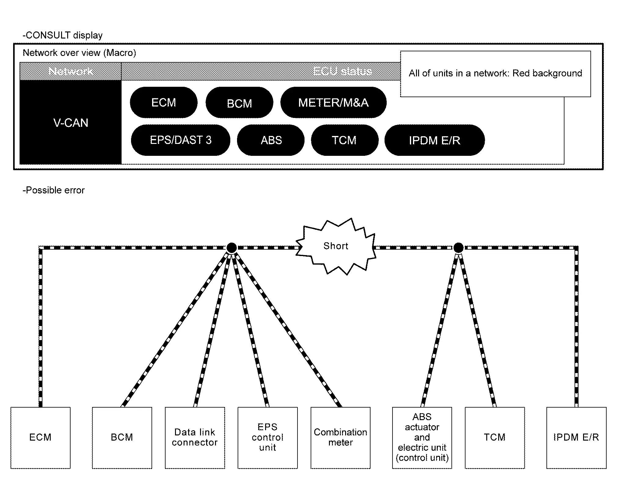
Example: CAN-H, CAN-L Harness Short Circuit

ItemDescription
CONSULT display All of units in a network with red backgrounds
Work procedure Perform diagnosis procedure for the CAN communication circuit.

How to Use Can Communication Signal Chart Nissan Ariya

System Description

The CAN communication signal chart lists the signals transmitted/received among control units. It is useful for detecting the root cause by finding a signal related to the symptom, and by checking transmission and reception unit.