System

In this manual: System
How to Use This Manual — 1Precautions — 1Preparation — 1Vehicle Information — 1Basic Inspection — 1Preparation. Commercial Service Tools Or/and Repair Part — 1Description — 1Component Parts — 1System — 1Diagnosis System (vcm) — 1Ecu Diagnosis Information. Vcm — 1Ev Control System — 1Ev/hev (vcm) — 1Component Parts /circuit Diagnosis — 1Ev Control System — 1Periodic Maintenance. Ev System Warning Lamp — 1Removal and Installation. Vcm — 1Traction Motor System :: Front Traction Motor — 1Preparation — 1Description — 4Basic Inspection — 2Dtc Diagnosis — 2Component Parts /circuit Diagnosis — 1Traction Motor System :: Rear Traction Motor — 1Description — 4Basic Inspection — 2Dtc Diagnosis — 2Component Parts /circuit Diagnosis — 1Removal and Installation — 1Ev Battery System :: 66kwh Li-Ion Battery — 1Description — 4Basic Inspection — 2Dtc Diagnosis — 2Component Parts /circuit Diagnosis — 1Removal and Installation — 1Disassembly and Assembly — 2Service Data — 1Ev Battery System :: 91kwh Li-Ion Battery — 1Description — 4Basic Inspection — 2Dtc Diagnosis — 2Component Parts /circuit Diagnosis — 1Removal and Installation — 1Disassembly and Assembly — 1Service Data — 2Preparation. Vehicle Charging System — 1Vehicle Charging System :: Description — 1Component Parts — 2System — 1Diagnosis System (on-Board Charger) — 1Diagnosis System (dc/dc Converter) — 1Ecu Diagnosis Information — 1Vehicle Charging System — 1Charger/pd Module (on-Board Charger) — 1Cplc (cplc) — 1Dcdc (dc/dc Converter) — 1Component Parts/circuit Diagnosis — 1Symptom Diagnosis — 1Evse Inspection — 1Periodic Maintenance — 1Removal and Installation — 1Disassembly and Assembly — 1Preparation. High Voltage Cooling System — 1Description — 1Symptom Diagnosis. Overheating Cause Analysis — 1Periodic Maintenance — 1Coolant — 1Removal and Installation — 1Radiator — 1Service Data — 1Removal and Installation. Accelerator Control System — 1Reduction Gear: Re1f62a — 1Removal and Installation — 1Transaxle & Transmission :: Electric Shift — 1Description — 3Basic Inspection — 2Dtc Diagnosis — 2Component Parts /circuit Diagnosis — 1Removal and Installation — 1Rear Final Drive: Rn1r62a — 1Removal and Installation — 1Preparation. Front Axle System — 1Symptom Diagnosis. Noise, Vibration and Harshness (nvh) Troubleshooting — 1Periodic Maintenance — 1Removal and Installation — 1Service Data. Front Drive Shaft — 12wd — 14wd — 1Periodic Maintenance — 1Removal and Installation — 1Preparation. Front Suspension System — 1Symptom Diagnosis. Noise, Vibration and Harshness (nvh) Troubleshooting — 1Periodic Maintenance — 1Removal and Installation — 1Service Data — 1Symptom Diagnosis. Noise, Vibration and Harshness (nvh) Troubleshooting — 1Periodic Maintenance — 1Removal and Installation — 1Service Data — 1Preparation. Road Wheels & Tires System — 1Description — 1System — 1Ecu Diagnosis Information. Bcm (body Control Module) — 1Tpms — 1Dtc/circuit Diagnosis — 1Symptom Diagnosis — 1Periodic Maintenance. Road Wheels & Tires — 1Removal and Installation — 1Service Data — 1Preparation. Brake System — 1System Description — 1Component Parts — 1Ecu Diagnosis Information. Electrically-Driven Intelligent Brake Unit — 1Basic Inspection — 1Dtc/circuit Diagnosis — 1Symptom Diagnosis — 1Periodic Maintenance — 1Removal and Installation — 1Service Data — 1Preparation. Parking Brake System — 1System Description — 1Component Parts — 1System — 1Ecu Diagnosis Information. Abs Actuator and Electric Unit (control Unit) — 1Basic Inspection. Diagnosis and Repair Work Flow — 1Component Parts /circuit Diagnosis — 1Symptom Diagnosis — 1Removal and Installation — 1Brake Control System :: With Vdc — 1System Description — 3Basic Inspection — 2Dtc/circuit Diagnosis — 1Symptom Diagnosis — 2Removal and Installation — 1Brake Control System :: Automatic Brake Hold — 1System Description — 3Component Parts /circuit Diagnosis — 1Removal and Installation — 1Brake Control System :: E-Step — 1System Description — 3Removal and Installation — 1System Description — 1Ecu Diagnosis Information — 1Basic Inspection — 1Symptom Diagnosis — 1Rear Automatic Braking — 1System Description — 1Basic Inspection — 1Preparation. Steering System — 1System Description — 1Component Parts — 1Basic Inspection — 1Dtc/circuit Diagnosis — 1Symptom Diagnosis — 1Periodic Maintenance. Steering Wheel — 1Removal and Installation — 1Service Data — 1System Description — 1Component Parts — 1Steering Control System — 1Ecu Diagnosis Information. Power Steering Control Module — 1Dtc/circuit Diagnosis — 1Component Parts /circuit Diagnosis — 1Symptom Diagnosis — 1Removal and Installation. Power Steering Control Module — 1System Description — 1Removal and Installation — 1System Description — 1System — 1Basic Inspection. Diagnosis and Repair Work Flow — 1Dtc/circuit Diagnosis — 1Symptom Diagnosis — 1Component Parts — 1Basic Inspection — 1Removal and Installation — 1System Description — 1System — 1Ecu Diagnosis Information. Air Bag Diagnosis Sensor Unit — 1Basic Inspection — 1Dtc/circuit Diagnosis — 1Symptom Diagnosis — 1System Description. Description. Ventilation System — 1Removal and Installation — 1Preparation. Preparation — 1System Description — 1Basic Inspection — 1Symptom Diagnosis — 1Removal and Installation — 1Electric Compressor — 1Cooler Pipe and Hose — 1A/c Unit Assembly Cover — 1A/c Unit Assembly — 1Heater & Air Conditioning Control System :: Automatic Air Conditioning — 1System Description — 1Ecu Diagnosis Information — 1Basic Inspection — 2Dtc Diagnosis — 1Symptom Diagnosis — 1Removal and Installation — 2Preparation. Preparation — 1Symptom Diagnosis. Squeak and Rattle Trouble Diagnoses — 1Removal and Installation — 1Preparation. Instrument Panel — 1Component Parts — 1System — 1Ecu Diagnosis Information. Flexible Center Storage Control Module — 1Basic Inspection. Diagnosis and Repair Work Flow — 1Dtc/circuit Diagnosis — 1Symptom Diagnosis — 1Removal and Installation — 1Preparation. Preparation — 1Component Parts — 1System — 1Ecu Diagnosis Information. Driver Lumbar Support Control Module — 1Basic Inspection. Diagnosis and Repair Work Flow — 1Dtc/circuit Diagnosis — 1Symptom Diagnosis — 1Removal and Installation — 1System Description — 1System — 1Ecu Diagnosis Information — 1Basic Inspection — 1Dtc/circuit Diagnosis — 1Symptom Diagnosis — 1Manual Function Does Not Operate — 1Memory Function Does Not Operate — 1Removal and Installation — 1Preparation. Preparation — 1System Description — 1System (intelligent Key System) — 1Diagnosis System (bcm) — 1Ecu Diagnosis Information — 1Basic Inspection — 1Dtc/circuit Diagnosis — 1U2141-87 Can Comm Circuit — 1Power Supply and Ground Circuit — 1Symptom Diagnosis — 1Automatic Back Door Operation Does Not Operate — 1Back Door Does Not Open — 1Door Does Not Lock/unlock with Door Lock and Unlock Switch — 1Removal and Installation — 1Hood — 1Radiator Core Support — 1Charge Port Lid — 1Front Fender — 1Front Door — 1Rear Door — 1Back Door — 1Hood Lock — 1Front Door Lock — 1Rear Door Lock — 1Back Door Lock — 1Outside Key Antenna — 1System Description — 1System — 1Ecu Diagnosis Information. Inverter (front), Inverter (rear), Bcm, Intelligent Key Unit — 1Basic Inspection — 1Dtc/circuit Diagnosis — 1Symptom Diagnosis — 1Preparation — 1Symptom Diagnosis. Squeak and Rattle Trouble Diagnoses — 1Removal and Installation — 1System Description — 1Ecu Diagnosis Information — 1Basic Inspection — 1Dtc/circuit Diagnosis — 1Power Supply and Ground Circuit — 1Symptom Diagnosis — 1Front Passenger Side Power Window Does Not Operate — 1Rear Lh Side Power Window Does Not Operate — 1Rear Rh Side Power Window Does Not Operate — 1Removal and Installation. Power Window Main Switch — 1Preparation. Preparation — 1System Description — 1Ecu Diagnosis Information — 1Basic Inspection — 1Dtc/circuit Diagnosis — 1Power Supply and Ground Circuit — 1Sunroof Switch Assembly — 1Symptom Diagnosis — 1Auto Operation Does Not Operate — 1Removal and Installation — 1Preparation — 1Description — 1Symptom Diagnosis. Squeak and Rattle Trouble Diagnoses — 1Removal and Installation — 1Service Information — 6Repair Information — 1Precaution — 1Preparation — 1Removal and Installation — 1Service Data — 1Preparation. Preparation — 1Component Parts — 1System — 1Ecu Diagnosis Information — 1Wiring Diagram. Door Mirror — 1Basic Inspection. Diagnosis and Repair Work Flow — 1Dtc/circuit Diagnosis — 1Power Supply and Ground Circuit — 1Symptom Diagnosis — 1Removal and Installation — 1Exterior Lighting System :: Led Headlamp — 1System Description — 3Basic Inspection — 1Dtc/circuit Diagnosis — 1Symptom Diagnosis — 1Periodic Maintenance — 1Removal and Installation — 1System Description — 1System — 1Diagnosis System (bcm) — 1Ecu Diagnosis Information. Bcm, Intelligent Key Unit — 1Basic Inspection. Diagnosis and Repair Work Flow — 1Dtc/circuit Diagnosis — 1Symptom Diagnosis. Interior Lighting System Symptom — 1Removal and Installation — 1Service Data. Bulb Specifications — 1System Description — 1System — 1Ecu Diagnosis Information. Bcm, Ipdm E/r — 1Basic Inspection. Diagnosis and Repair Work Flow — 1Dtc/circuit Diagnosis — 1Symptom Diagnosis — 1Removal and Installation — 1System Description — 1Ecu Diagnosis Information. Bcm — 1Basic Inspection. Diagnosis and Repair Work Flow — 1Dtc/circuit Diagnosis — 1Symptom Diagnosis — 1Removal and Installation — 1Preparation. Preparation — 1Removal and Installation. Horn — 1Preparation. Commercial Service Tools Or/and Repair Part — 1System Description — 1Component Parts — 1Ecu Diagnosis Information. Approaching Vehicle Sound for Pedestrians (vsp) Control Unit — 1Approaching Vehicle Sound for Pedestrians (vsp) — 1Vsp [approaching Vehicle Sound for Pedestrians (vsp) Control Unit] — 1Approaching Vehicle Sound for Pedestrians (vsp) System — 1Removal and Installation — 1Removal and Installation — 1Wireless Charger — 1System Description — 1Basic Inspection — 1Dtc/circuit Diagnosis — 1Removal and Installation — 1Component Parts — 1System — 1Diagnosis System (bcm) — 1Ecu Diagnosis Information. Bcm — 1Basic Inspection — 1Dtc/circuit Diagnosis — 1Symptom Diagnosis — 1Removal and Installation — 1Can Fundamental — 1Description — 1Trouble Diagnosis — 1Can (controller Area Network) — 1Description — 1
6steps
~36min
4/5difficulty
Done 0 of 6
  • Tpms
  • Warning/indicator/chime List
  • Operation

Tpms Nissan Ariya

System Description

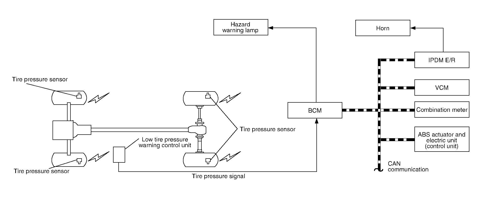
  • During driving, the TPMS (Tire Pressure Monitoring System) receives the signal transmitted from tire pressure sensor installed in each wheel. The low tire pressure warning control unit of this system has pressure judgment and trouble diagnosis functions. When the TPMS detects low inflation pressure or another unusual symptom, the low tire pressure warning lamps in the combination meter comes on.

  • Tire pressure varies as per the change in tire temperature. Therefore, warning tire pressure value is varied as per the change in tire temperature. TPMS calibration is required for recording basic temperature and tire pressure at the time of adjusting tire pressure.
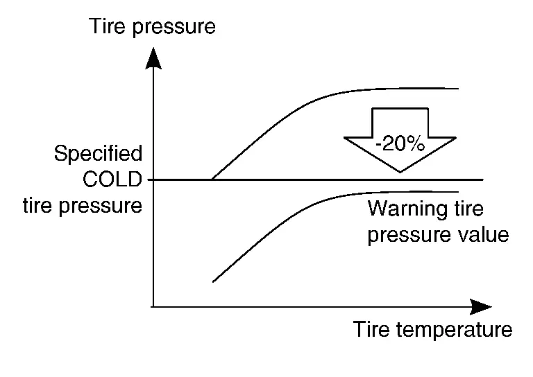
  • If the tire pressure is less than the warning tire pressure value, the low tire pressure warning lamp illuminates.

  • Location of wheel is specified due to the synchronism of wheel sensor position and tire pressure sensor position.

  • Activates the TPMS when the Nissan Ariya vehicle speed is 40 km/h or more.

SYSTEM DIAGRAM
INPUT/OUTPUT SIGNAL

Major signal transmission between each unit via communication lines is shown in the following table:

Component partsSignal item
Combination meter

Mainly receives the following signals from BCM via CAN communication:

  • Low tire pressure warning lamp signal

  • Low tire pressure wheel location signal

  • TPMS malfunction warning lamp signal

  • ECO advise signal
ABS actuator and electric unit (control unit)

Mainly transmits the following signals to BCM via CAN communication:

  • Nissan Ariya Vehicle speed signal (ABS)

BCM

Mainly transmits the following signals to combination meter via CAN communication:

  • Low tire pressure warning lamp signal

  • Low tire pressure wheel location signal

  • TPMS malfunction warning lamp signal

  • ECO advise signal

Mainly receives the following signal from ABS actuator and electric unit (control unit) via CAN communication:

  • Nissan Ariya Vehicle speed signal (ABS)

  • Horn request signal

Mainly receives the following signal from TCMa via CAN communication

  • Shift position signal

TCM

Mainly transmits the following signals to BCM via CAN communication.

  • Shift position signal

IPDM E/R

Mainly receives the following signals from BCM via CAN communication.

  • Horn request signal

LOW TIRE PRESSURE WARNING LAMP INDICATION CONDITION

Uses CAN communication from the low tire pressure warning control unit to illuminate the low tire pressure warning lamp on the combination meter.

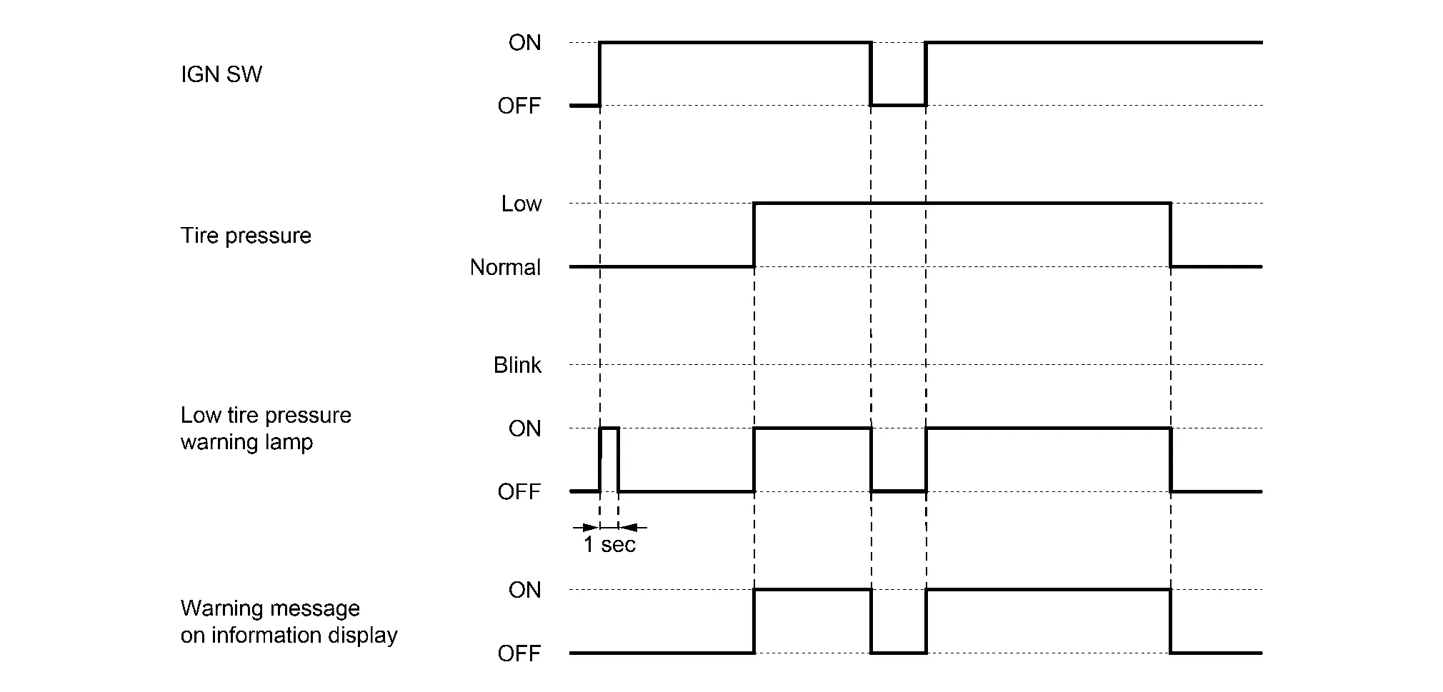
ConditionLow tire pressure warning lamp
Power switch OFF OFF

Power switch ON

(system normal)
Warning lamp turns ON for 1 second, then turns OFF.
Low tire pressure ON
Configuration not performed in tire pressure monitoring system Warning lamp blinks 1 minute, then turns ON.
Tire pressure monitoring system malfunction

HAZARD WARNING LAMP INDICATION CONDITION

The hazard warning lamp blinks under the following conditions:

  • When ID registration is completed. Refer to Description.

HORN CONTROL CONDITION

During the use of the easy fill tire alert function.

EASY FILL ALERT FUNCTION

  • This function operates only when the select lever position is in P-range with the power switch ON or with the Nissan Ariya vehicle set to READY.

  • The Easy Fill Tire Alert function operates only when the select lever position is in P-range with the power switch ON.

  • This function informs the driver with a visual and audible indication that the recommended COLD tire pressure has been reached.

  • The hazard warning lamps blink when the recommended COLD tire pressure has been reached. After the recommended COLD tire pressure has been reached, the horn sounds once and the hazard warning lamps stop blinking.
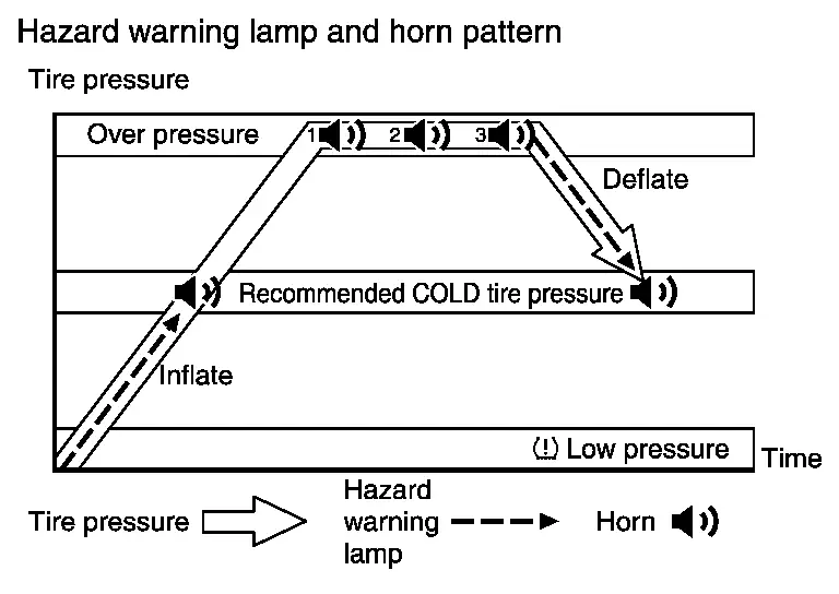
  • If the tire pressure value is equal to or greater than 4 psi (0.31 kg/cm2, 30 kPa) more than the recommended COLD tire pressure, the hazard warning lamps flash and horn sounds three times.

  • To return the tire to the recommended COLD tire pressure, deflate the tire until the horn sounds once and the hazard warning lamps stop blinking.

Circuit Diagram

Warning/indicator/chime List Nissan Ariya 1st generation

Warning Lamp/Indicator Lamp

FULL TFT METER

NameDesignLayout/Function
Low tire pressure warning lamp For layout, refer to Design.
For function, refer to .
NameLayout/Function
Low tire pressure warning Refer to Low tire Pressure Warning.
Tire pressure display Refer to Tire Pressure display.

Low Tire Pressure Warning

DESIGN/PURPOSE

The low tire pressure location indicator is displayed in the information display of combination meter with the low tire pressure warning lamp and warning message when following conditions;

  • Tire pressure is low.

  • Tire goes flat.

SymbolMassage

Tire Pressure Low

Add Air

SYNCHRONIZATION WITH MASTER WARNING LAMP

Applicable to low tire pressure warning lamp lighting by low air pressure. Refer to Master Warning Lamp.

SYSTEM DIAGRAM
SIGNAL PATH

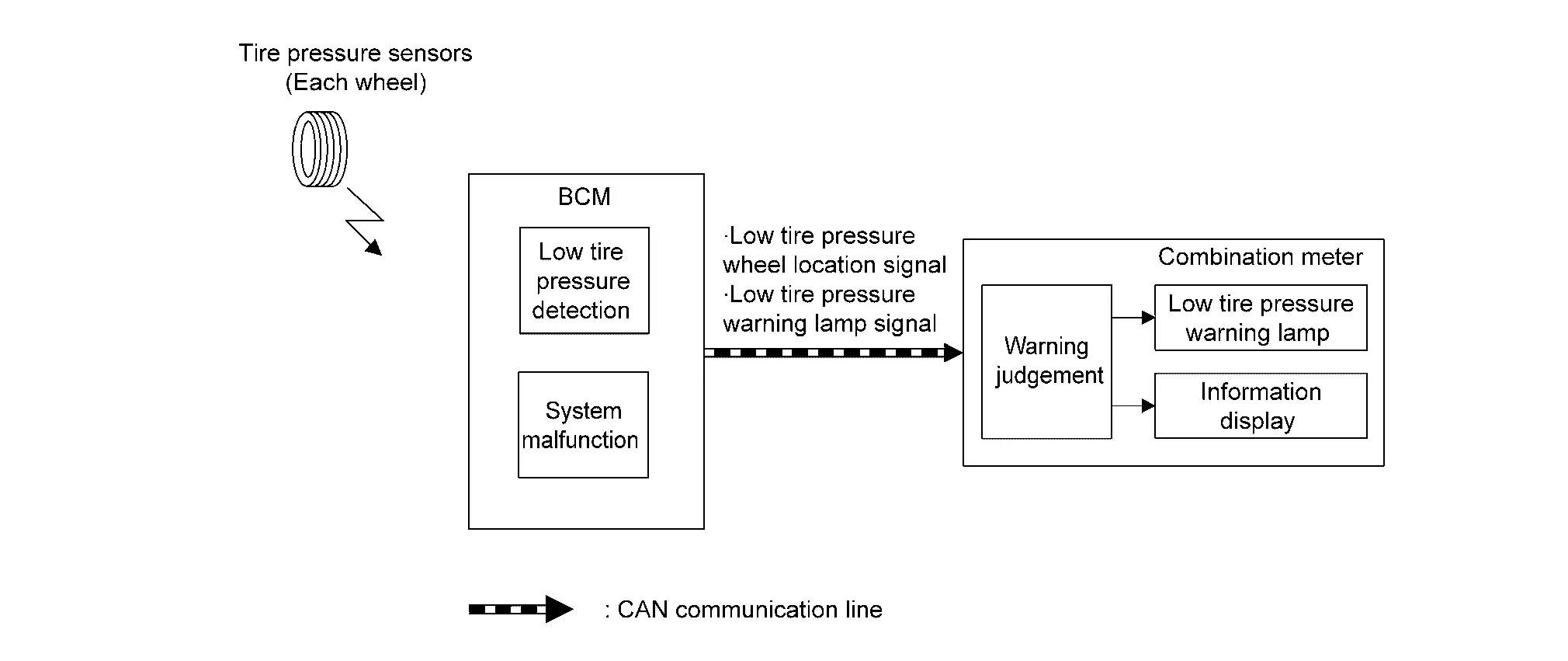
  • BCM receives a signal transmitted from the tire pressure sensors installed in each wheel.

  • If BCM detects following condition, it sends the signal to the combination meter via CAN communication.

    • Tire pressure is low

  • Combination meter turns the low tire pressure warning lamp ON. In addition, warning message will be displayed in the information display.

  • Tire pressure is low

  • Tire pressure is extremely low (flat tire)

  • Erasing DTC records.

  • Tire pressure of all the tires reaches the reference value. For the reference value of tire pressure, refer to Tire Air Pressure.

TIMING CHART
Tire Pressure Display

The adoption of this function allows tire pressure indication on the information display installed to the combination meter.

FULL TFT METER
DesignDescription
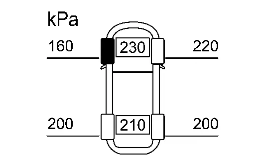
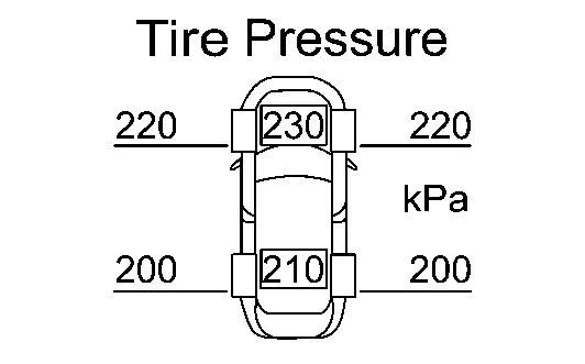
The tire pressure of each tire is displayed.
ECO DRIVE REPORT INFORMATION
MessageDescription
See Tire Pressure The tire pressure of each tire is low.
ECO DRIVE REPORT MESSAGE
MessageDescription
Check Tire Pressures for Best Fuel Economy Adjust the tire pressure for each tire.

SYSTEM DIAGRAM

SIGNAL PATH

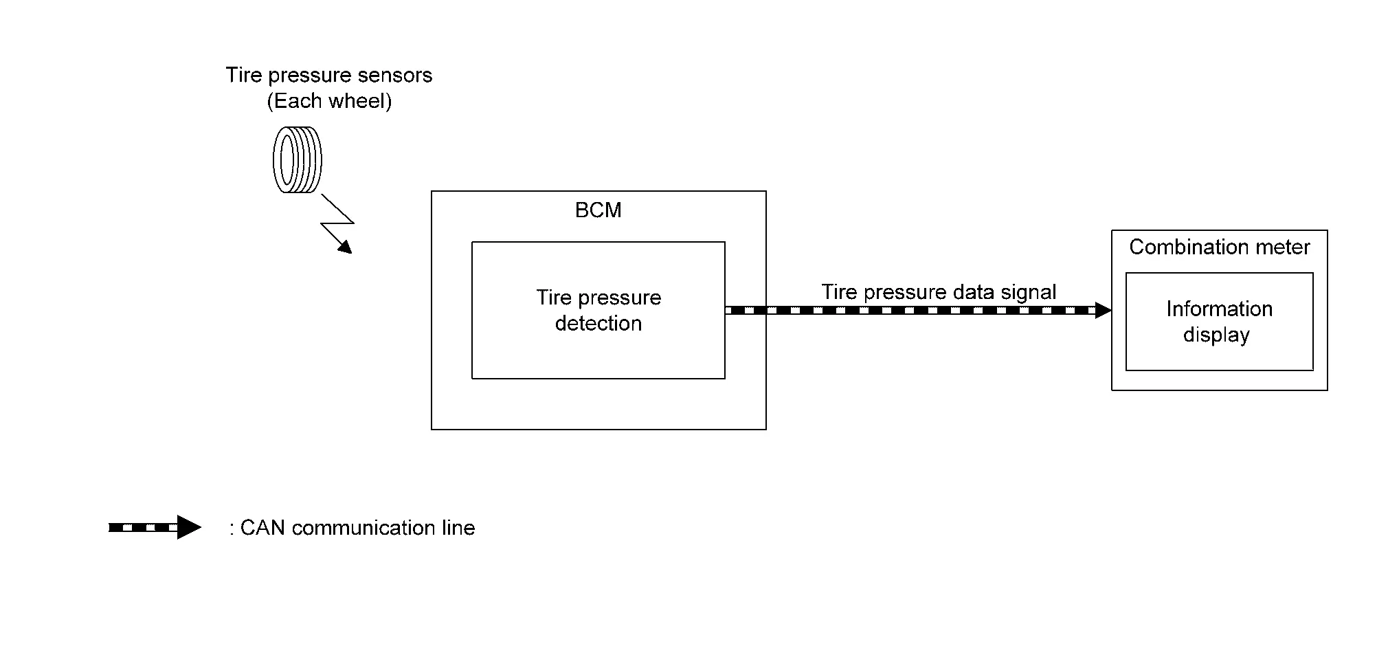
  • BCM receives a signal transmitted from the tire pressure sensors installed in each wheel.

  • BCM transmits a tire pressure data signal to the combination meter via CAN communication.

  • The combination meter displays tire pressure of each tire on the information display when receiving a tire pressure data signal.

Operation Nissan Ariya: FE0

Switch Name and Function

TIRE PRESSURE UNIT

Description

Following item can be set on the information display.

Switch nameItemDescription
TPMS setting Tire Pressure Unit

Tire air pressure unit can be adjusted.

  • kPa

  • psi

  • bar

  • kgf/cm2

Setting Follow

On the information display

Tire Pressure Unit

  1. Select the MENU button and “Settings” on the information display.

  2. Select “TPMS Setting”.

  3. Select “Tire Pressure Unit”.

  4. When setting of TPMS unit changed, touch select “kPa”, “psi”, “bar” or “kgf/cm2”.

TIRE PRES ECO ADVICE

Description

“Tire Pres ECO advice” can be set ON/OFF on the information display.

Setting Follow

On the information display

Tire Pres ECO Advice

  1. Select the MENU button and “ECO Mode Settings” on the information display.

  2. Select “Tire Pres ECO advice”.