Cooler Pipe and Hose
Exploded View
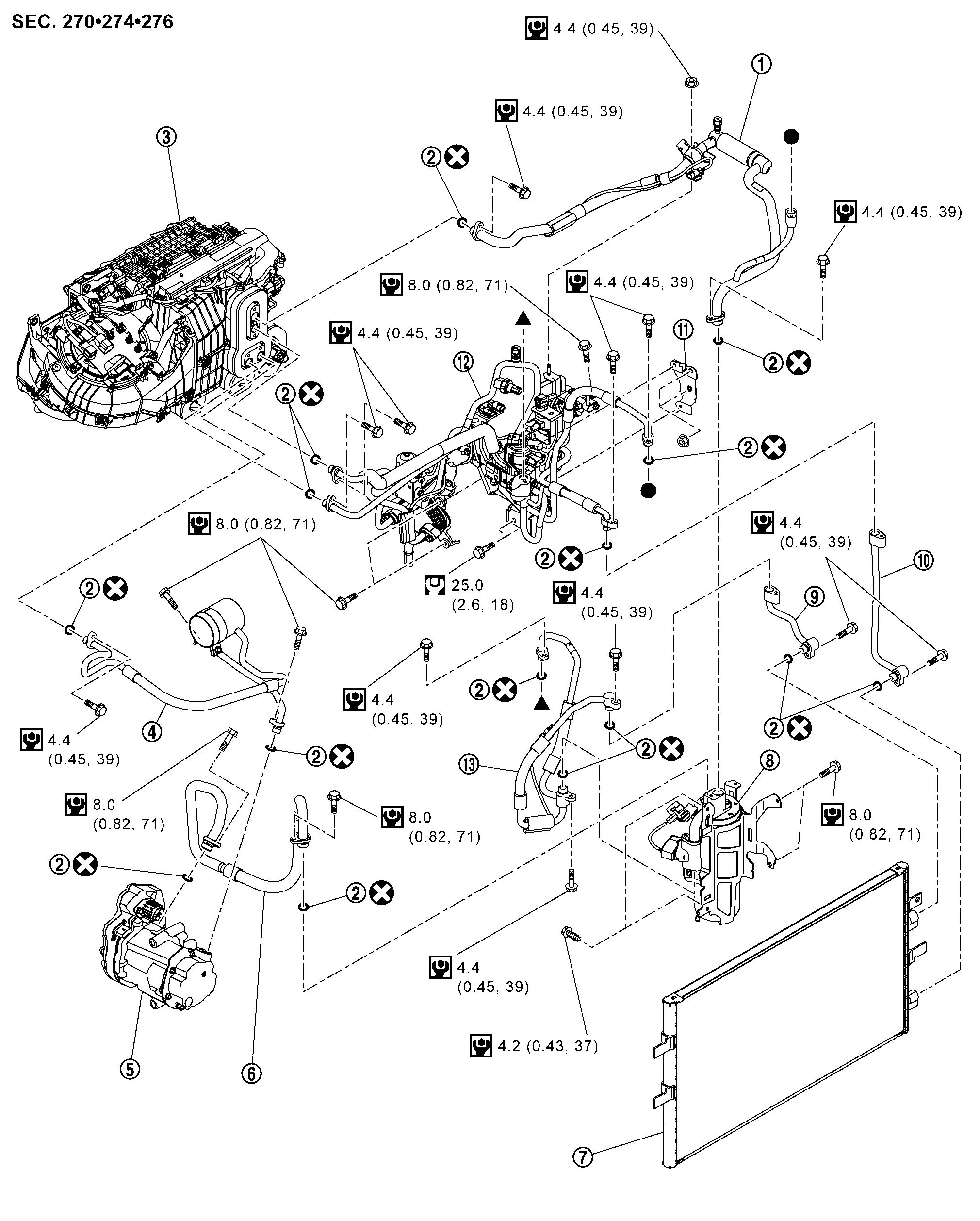
 |
Low-pressure refrigerator pipe assembly |  |
O-ring |  |
A/C unit assembly |
 |
High-pressure flexible hose |  |
Electric compressor |  |
Low-pressure flexible hose |
 |
Condenser |  |
Accumulator assembly |  |
Cooler pipe A |
 |
Cooler pipe B |  |
Bracket |  |
High-pressure cooler pipe assembly |
 |
High-pressure flexible pipe assembly | ||||
 |
: Always replace after every disassembly. | ||||
 |
: N•m (kg-m, in-lb) | ||||
 ,  : Indicates that the part is connected at points with same symbol in actual Nissan Ariya vehicle. |
|||||
HIGH-PRESSURE COOLER PIPE ASSEMBLY
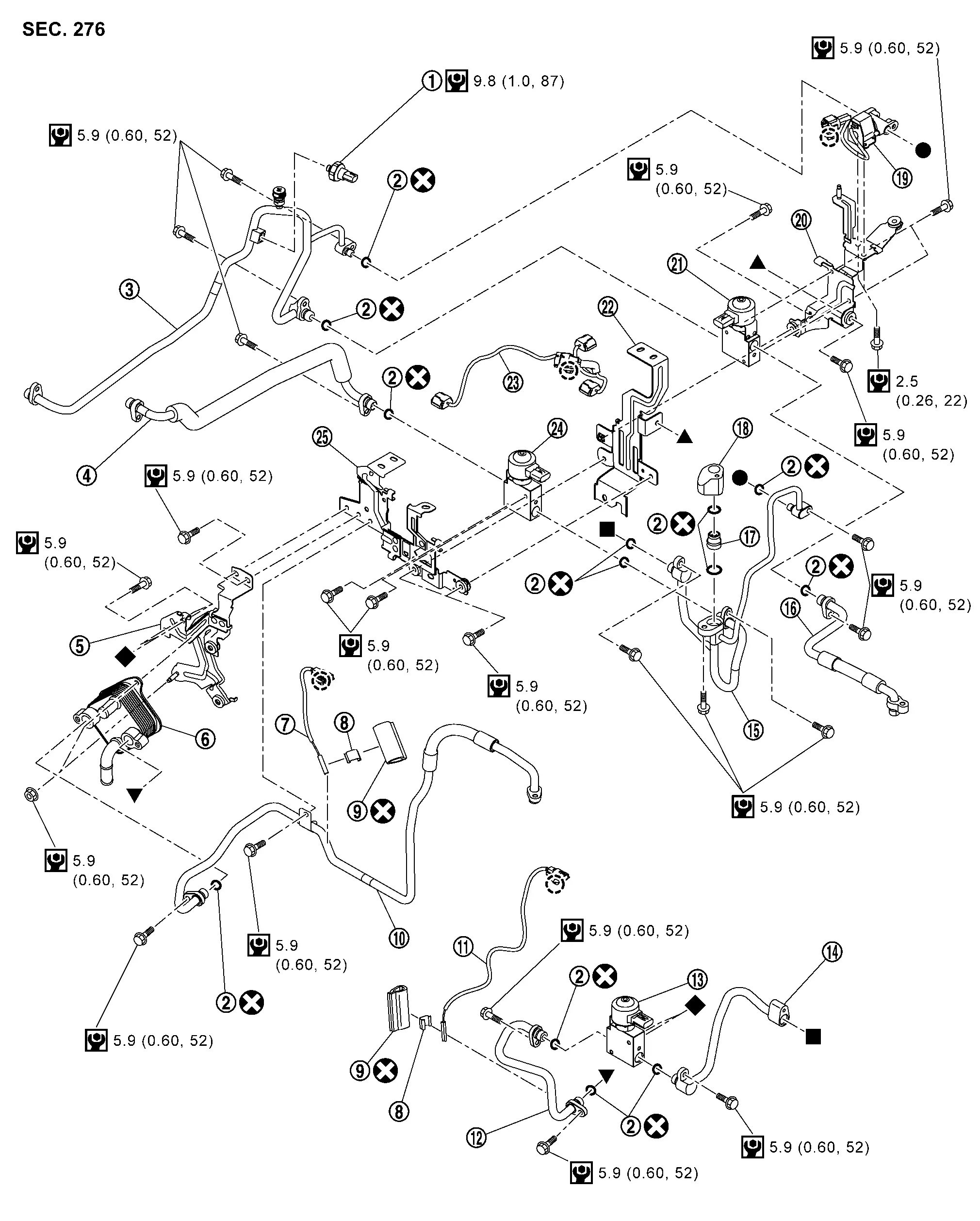
|
Refrigerant pressure sensor | |
O-ring | |
High-pressure cooler pipe 1 |
|
High-pressure cooler pipe 2 | |
Bracket 4 | |
Battery coolant chiller |
|
Refrigerant temperature sensor (battery chiller outlet) | |
Sensor clip | |
Foam seal |
|
High-pressure cooler pipe 7 | |
Refrigerant temperature sensor (battery chiller inlet) | |
High-pressure cooler pipe 6 |
|
Expansion valve (battery chiller) |  |
High-pressure cooler pipe 8 |  |
High-pressure cooler pipe 3 |
 |
High-pressure cooler pipe 5 |  |
1 way valve |  |
High-pressure cooler pipe 4 |
 |
High pressure refrigerant channel switching valve |  |
Bracket 1 |  |
Electric expansion valve (heater) |
 |
Bracket 2 |  |
Sub harness |  |
Electric expansion valve (cooler) |
 |
Bracket 3 | ||||
 |
: Clip | ||||
|
: Always replace after every disassembly. | ||||
|
: N•m (kg-m, in-lb) | ||||
, ,  ,  ,  : Indicates that the part is connected at points with same symbol in actual Nissan Ariya vehicle. |
|||||
HIGH-PRESSURE FLEXIBLE PIPE ASSEMBLY
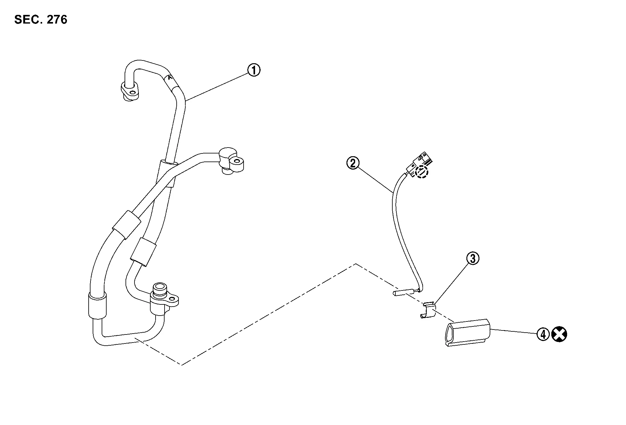
|
High-pressure flexible pipe | |
Condencer discharge refrigerant temperature sensor | |
Sensor clip |
|
Foam seal | ||||
|
: Clip | ||||
|
: Always replace after every disassembly. | ||||
LOW-PRESSURE REFRIGERATOR PIPE ASSEMBLY

|
Evaporator discharge refrigerant temperature sensor | |
Tape | |
Foam seal |
|
Sensor clip | |
Low-pressure refrigerator pipe 1 | |
Low-pressure refrigerator pipe 2 |
|
O-ring | |
Evaporator pressure regulator | ||
|
: Always replace after every disassembly. | ||||
|
: N•m (kg-m, in-lb) | ||||
ACCUMULATOR ASSEMBLY
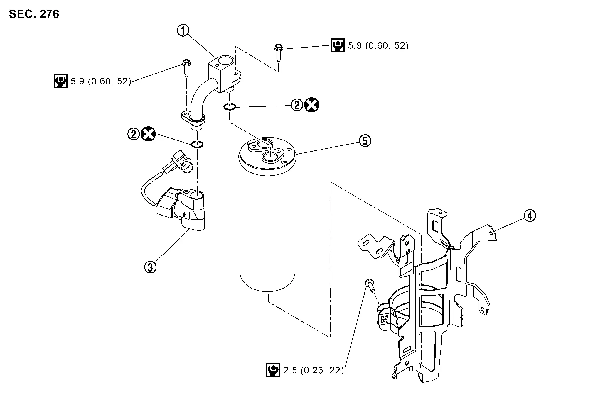
|
Low-pressure pipe | |
O-ring | |
Low pressure refrigerant channel switching valve |
|
Bracket | |
Accumulator | ||
|
: Clip | ||||
|
: Always replace after every disassembly. | ||||
|
: N•m (kg-m, in-lb) | ||||
- High-Pressure Flexible Hose
- High-Pressure Cooler Pipe Assembly
- High-Pressure Flexible Pipe Assembly
- Low-Pressure Refrigerator Pipe Assembly
- Cooler Pipe a
- Accumulator Assembly
- Refrigerant Pressure Sensor
High-Pressure Flexible Hose Nissan Ariya first Gen
Removal & Installation
DANGER: Since hybrid vehicles and electric vehicles contain a high voltage battery, there is the risk of electric shock, electric leakage, or similar accidents if the high voltage component and Nissan Ariya vehicle are handled incorrectly. Be sure to follow the correct work procedures when performing inspection and maintenance.
REMOVAL
Follow the instructions below before starting the procedure.
Use a refrigerant collecting equipment (for HFO-1234yf) to discharge the refrigerant. Refer to Recycle Refrigerant.
Remove high voltage power delivery assembly. Refer to HIGH VOLTAGE POWER DELIVERY ASSEMBLY : Removal & Installation.
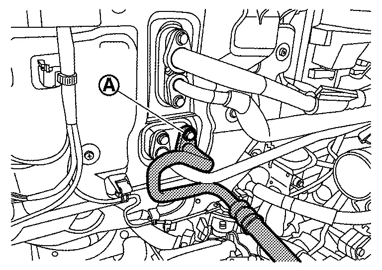
Remove mounting bolt  , and then disconnect high-pressure flexible hose from A/C unit assembly.
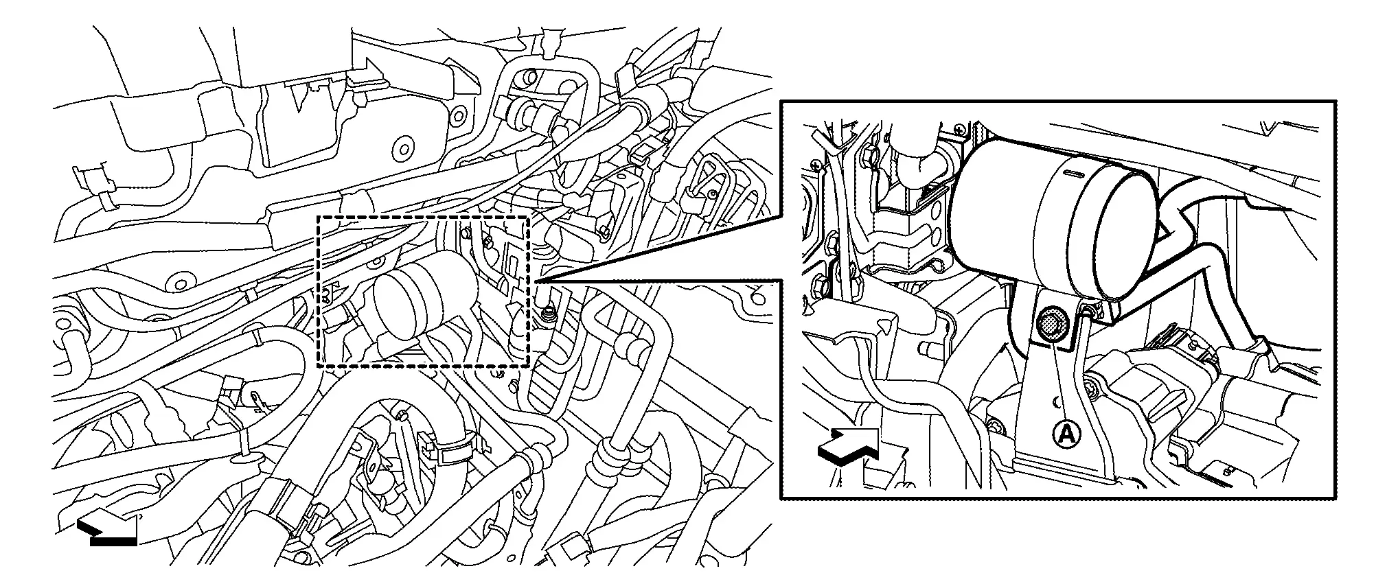
Remove mounting bolt , and then remove high-pressure flexible hose from compressor stay.
 |
:Front Nissan Ariya vehicle | ||||
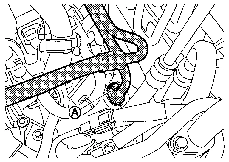
Remove mounting bolt , and then disconnect high-pressure flexible hose from electric compressor.


Remove high-pressure flexible hose from Nissan Ariya vehicle.
INSTALLATION
Note the following items, and then install in the reverse order of removal.
High-Pressure Cooler Pipe Assembly Nissan Ariya 1st generation
Removal & Installation
REMOVAL
Use a refrigerant collecting equipment (for HFO-1234yf) to discharge the refrigerant. Refer to Recycle Refrigerant.
Remove electric compressor. Refer to Removal & Installation.
Disconnect water hoses from battery coolant chiller.
Remove mounting bolt , and then disconnect high-pressure cooler pipe assembly from low-pressure refrigerator pipe assembly.

Remove low-pressure refrigerator pipe assembly. Refer to Removal & Installation.
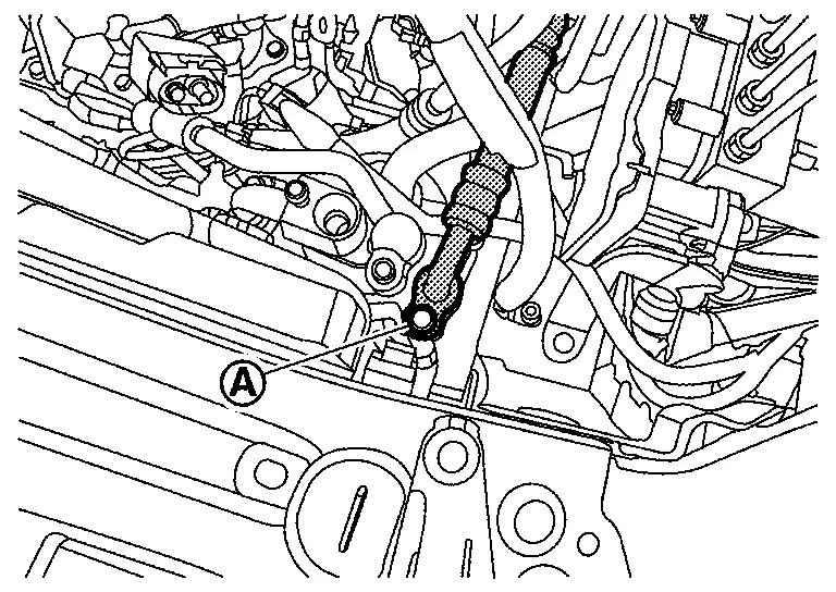
Remove mounting bolt , and then disconnect high-pressure cooler pipe assembly from cooler pipe B.
Disconnect high-pressure flexible pipe assembly from high-pressure cooler pipe assembly. Refer to Removal & Installation.
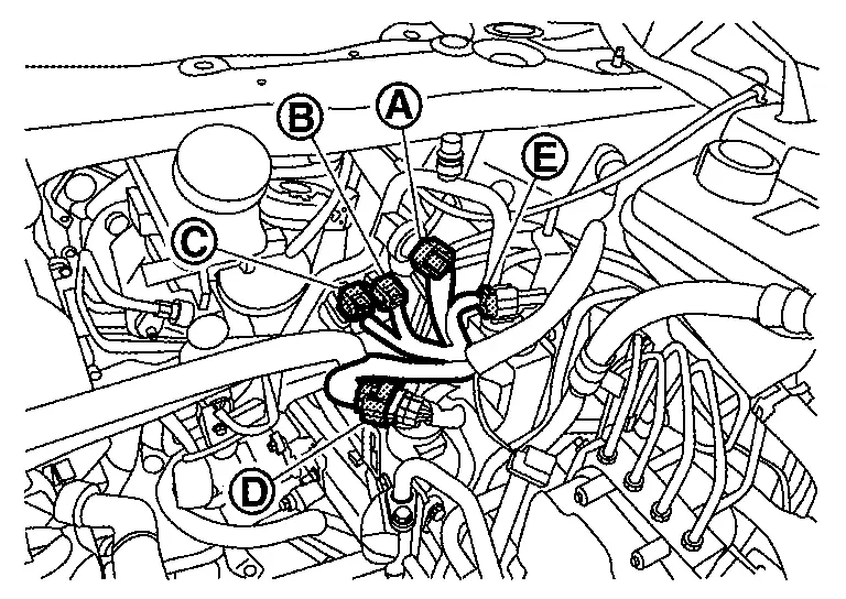
Disconnect harness connectors to  .
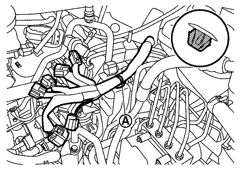
Disengage harness fixing clip .
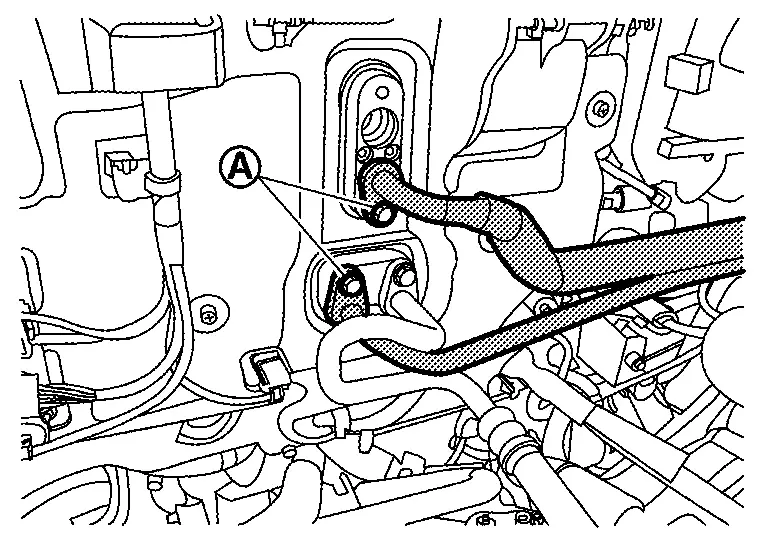
Remove mounting bolts , and then disconnect high-pressure cooler pipe assembly from A/C unit assembly.
Remove mounting bolt, and then move reservoir tank to secure work space. Refer to RADIATOR : Exploded View.
Remove the lower mounting bolt of the high-pressure cooler pipe assembly and loosen  .
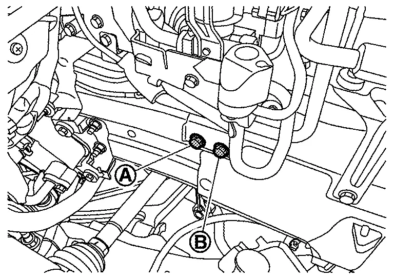
Remove upper mounting bolt of the high pressure cooler pipe assembly.
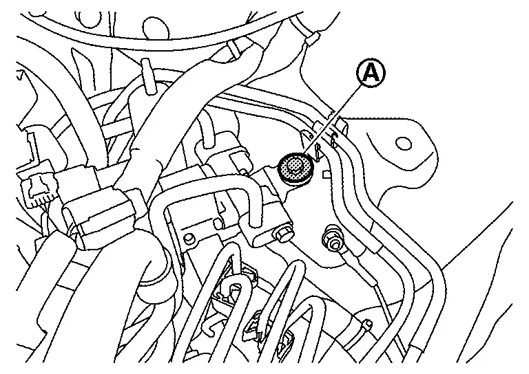
Remove rear mounting bolts of the high-pressure cooler pipe assembly.
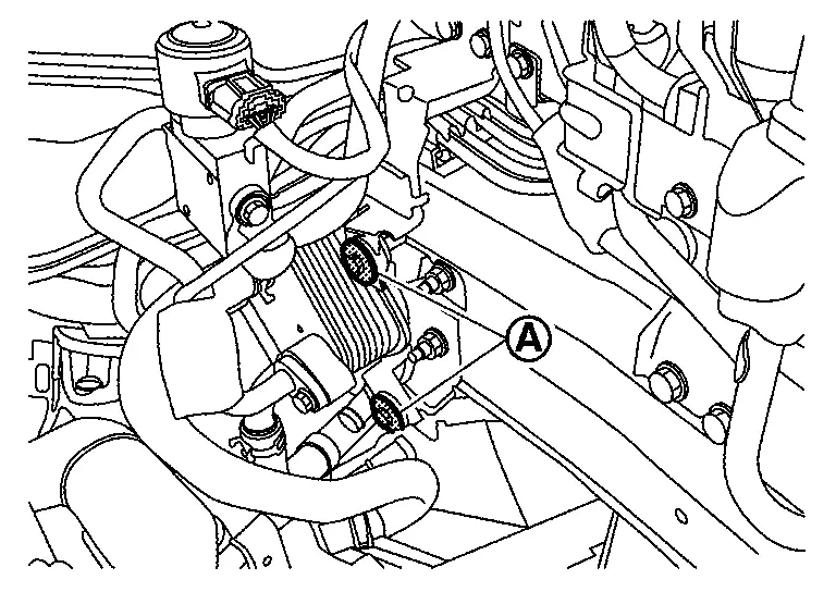
Remove high-pressure cooler pipe from Nissan Ariya vehicle.
INSTALLATION
Note the following items, and then install in the reverse order of removal.
Tighten high-pressure cooler pipe assembly mounting bolts according to the following order.
Temporarily attach lower mounting bolt of high-pressure cooler pipe assembly and temporarily place bracket part of high-pressure cooler pipe assembly.

Temporarily tighten lower mounting bolts of high-pressure cooler pipe assembly.
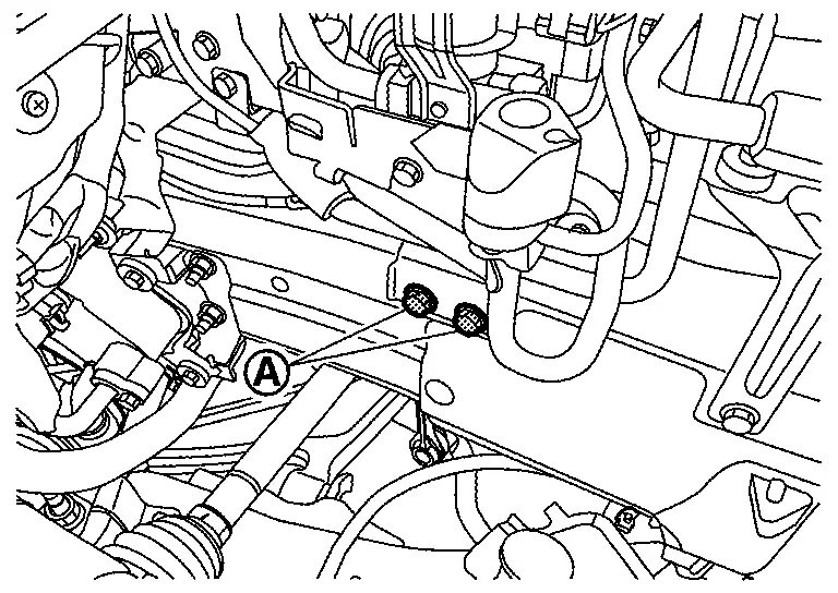
Temporarily tighten upper mounting bolt of high-pressure cooler pipe assembly.
Tighten rear mounting bolts of high-pressure cooler pipe assembly to the specified torque value.
Tighten upper mounting bolt of high-pressure cooler pipe assembly to the specified torque value.
Tighten lower mounting bolts of high-pressure cooler pipe assembly to the specified torque value.
Disassembly & Assembly
DISASSEMBLY
Remove sub harness.Disconnect harness connectors of electric expansion valve (cooler) , electric expansion valve (heater) and expansion valve (battery chiller)  .
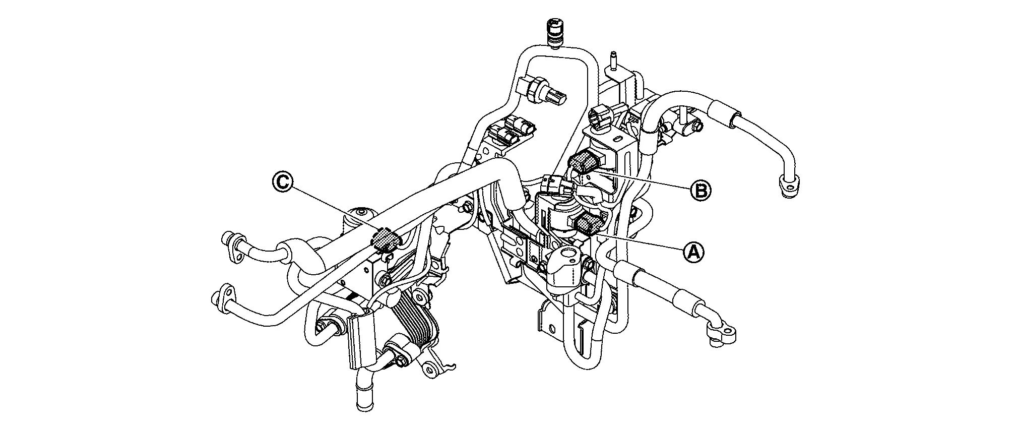
Remove refrigerant temperature sensor (battery chiller outlet) and refrigerant temperature sensor (battery chiller inlet).Peel foam seal. Disengage sensor clip, and then remove sensor from high-pressure cooler pipe. Disengage refrigerant temperature sensor (battery chiller outlet) harness connector fixing clip and refrigerant temperature sensor (battery chiller inlet) harness connector fixing clip from bracket 3, and then remove refrigerant temperature sensor (battery chiller inlet) and refrigerant temperature sensor (battery chiller outlet) .
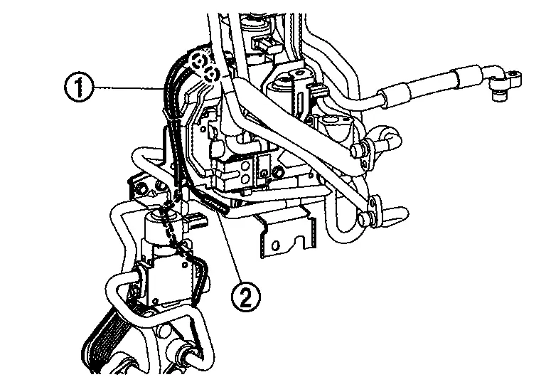
|
: Clip | ||||
Remove high-pressure cooler pipe 7.Remove tube clamp mounting bolt .
 , and then remove high-pressure cooler pipe 7 from battery coolant chiller.
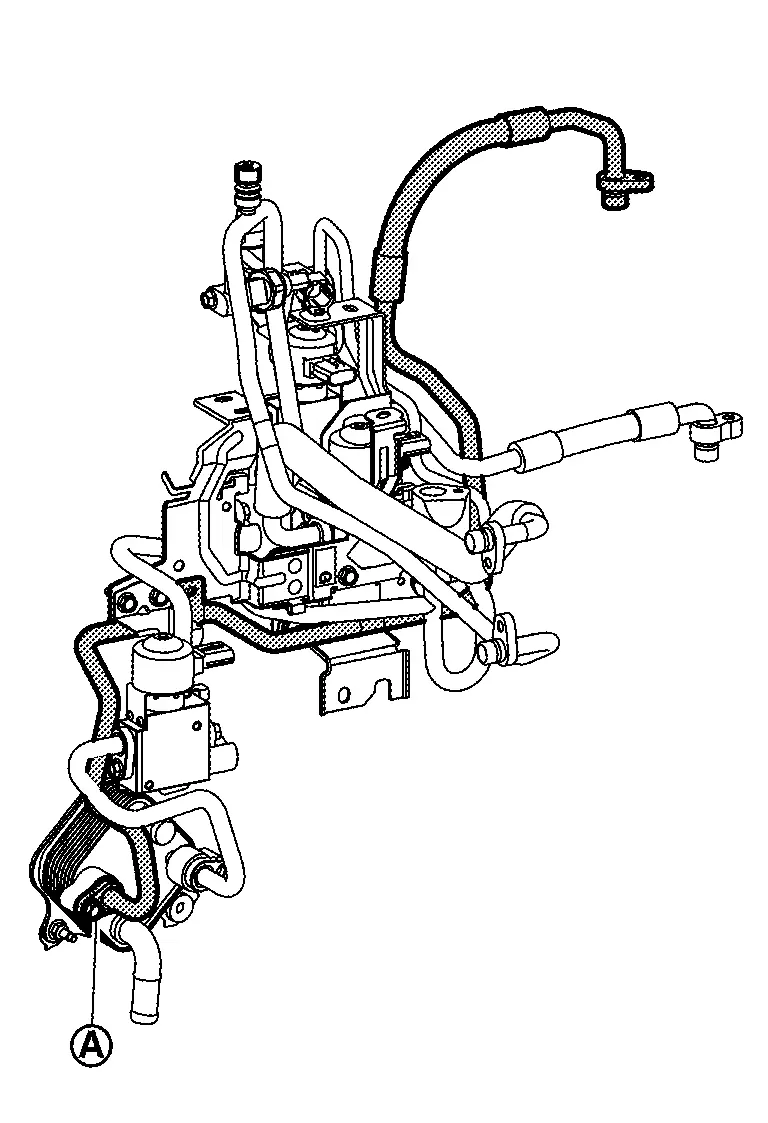
Remove mounting bolt , and then high-pressure cooler pipe 5 from electric expansion valve (heater).

Remove expansion valve (battery chiller), high-pressure cooler pipe 6 and battery coolant chiller.Remove high-pressure cooler pipe 8 mounting bolt .
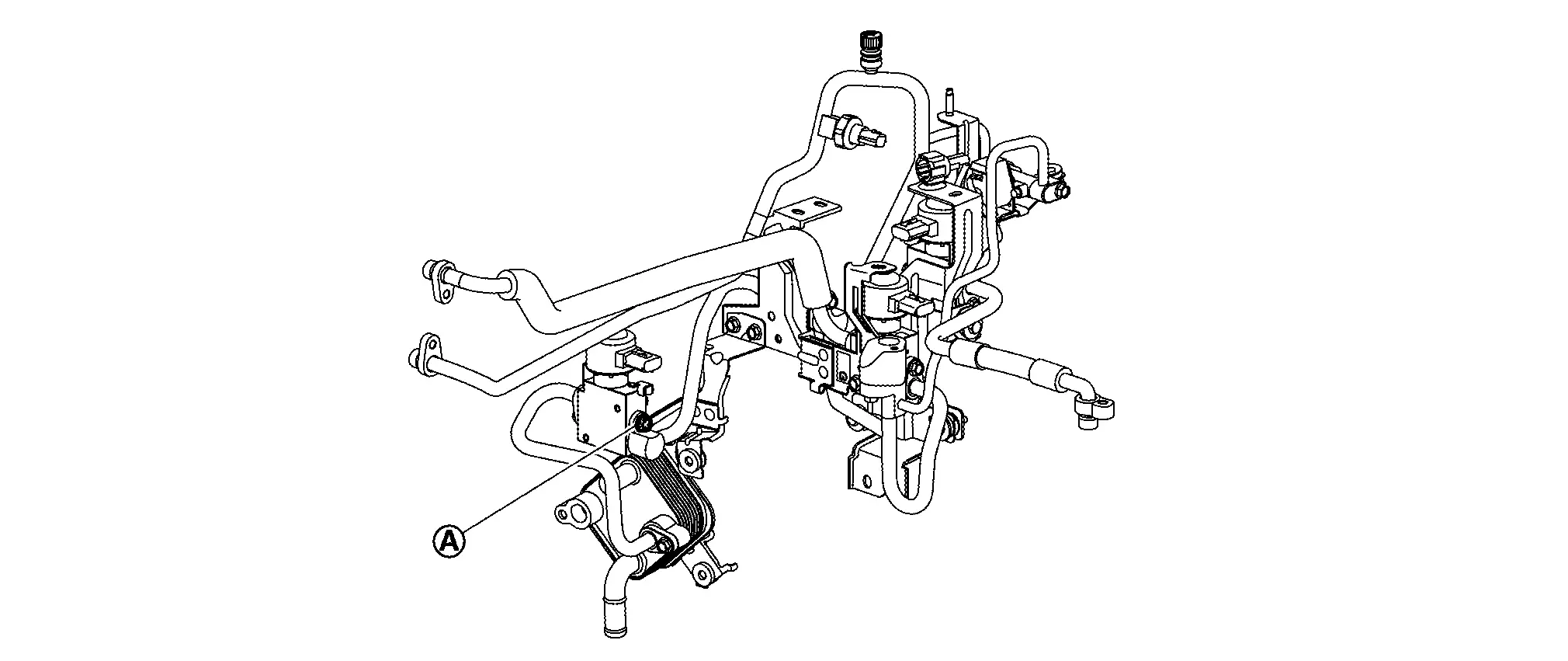 , and then remove bracket 4, battery coolant chiller, high-pressure cooler pipe 6 and expansion valve (battery chiller) as a set from bracket 3.
 .
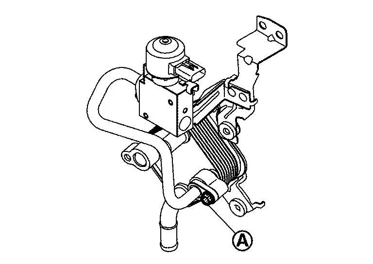 , and then remove expansion valve (battery chiller) and high-pressure pipe 6 as a set.
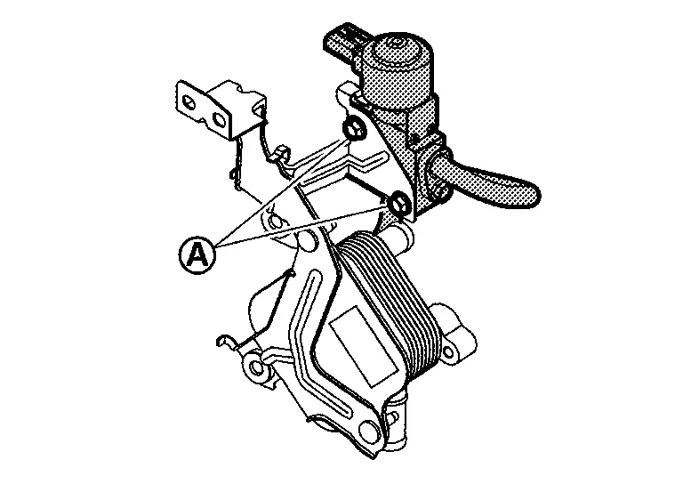
Remove electric expansion valve (cooler), high-pressure cooler pipe 2, high-pressure cooler pipe 3 and high-pressure cooler pipe 8.Remove high-pressure cooler pipe 3 mounting bolt .
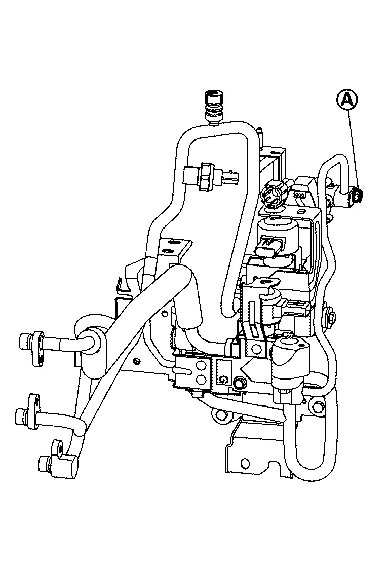 , and then remove bracket 3, electric expansion valve (cooler), high-pressure cooler pipe 2, high-pressure cooler pipe 3 and high-pressure cooler pipe 8 as a set from bracket 2.
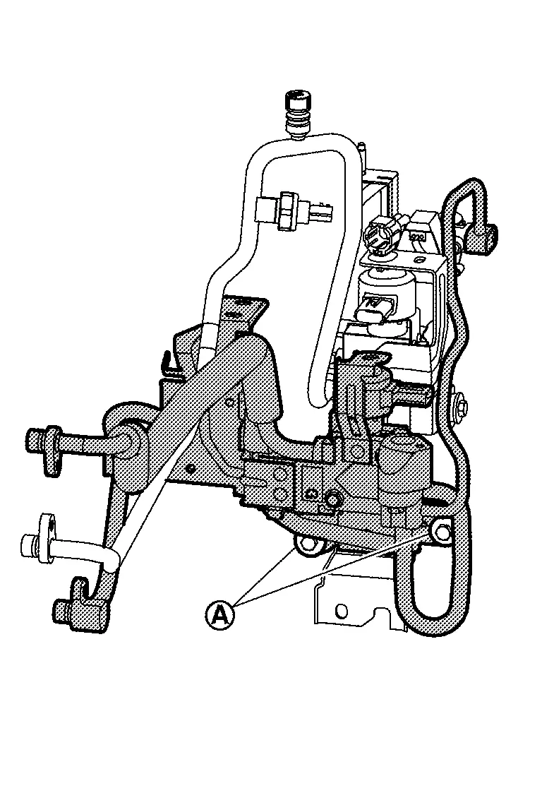 , and then remove high-pressure cooler pipe 3 and high-pressure cooler pipe 8 as a set from electric expansion valve (cooler) .
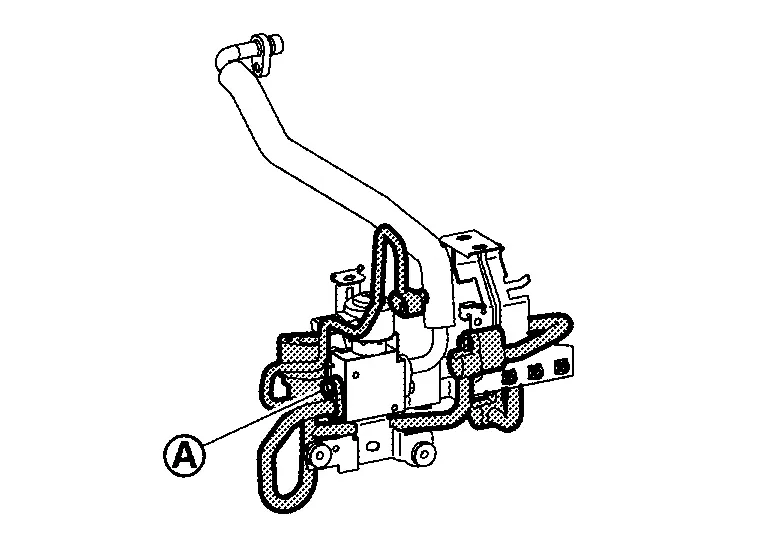 and then remove electronic expansion valve (cooler) and high-pressure cooler pipe 2 as a set from bracket 3.

Remove mounting bolts , and then remove high-pressure cooler pipe 1 from high pressure refrigerant channel switching valve and electric expansion valve (heater) .
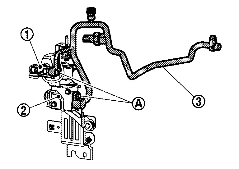
Remove electric expansion valve (heater) and high pressure refrigerant channel switching valve.Disengage fixing clip of high pressure refrigerant channel switching valve harness connector from bracket 2 .
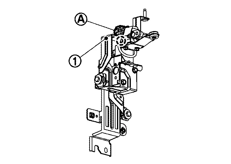
|
: Clip | ||||
, and then remove bracket 1, electronic expansion valve (heater), and high pressure refrigerant channel switching valve as a set from bracket 2. 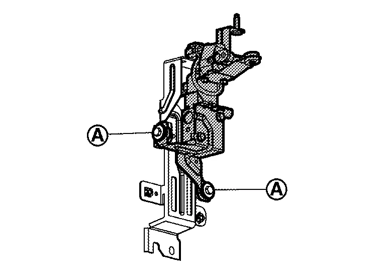 , and then remove electronic expansion valve (heater) from bracket 1.
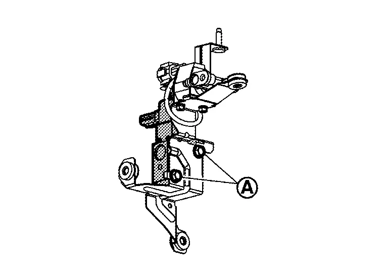
ASSEMBLY
Note the following items, and then assemble in the reverse order of disassembly.
High-Pressure Flexible Pipe Assembly Nissan Ariya 2026
Removal & Installation
REMOVAL
Use a refrigerant collecting equipment (for HFO-1234yf) to discharge the refrigerant. Refer to Recycle Refrigerant.
Remove low-pressure refrigerator pipe assembly. Refer to Removal & Installation.
Disconnect Nissan Ariya vehicle harness connectors and from high pressure refrigerant channel switching valve harness connector and condenser discharge refrigerant temperature sensor harness connector.
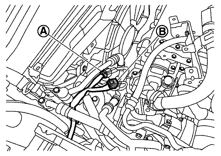
Remove connector fixing clips of high pressure refrigerant channel switching valve harness connector and condenser discharge refrigerant temperature sensor harness connector from bracket of accumulator assembly.
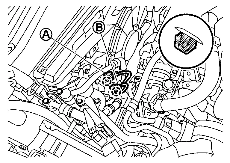
|
: Clip | ||||
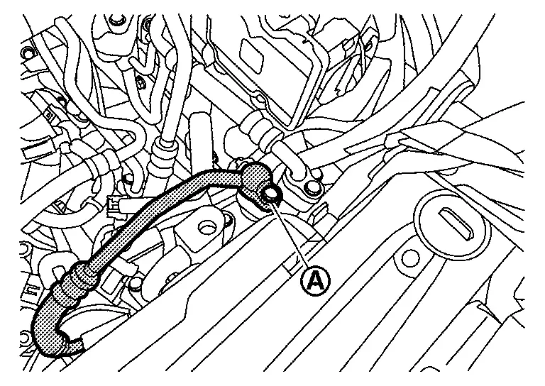
Remove mounting bolt , and then disconnect high-pressure flexible pipe assembly from cooler pipe A.
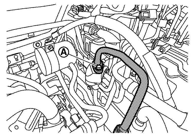
Remove mounting bolt , and then disconnect high-pressure flexible pipe assembly from high-pressure cooler pipe assembly.
Remove low-pressure pipe mounting bolt of Accumulator assembly.
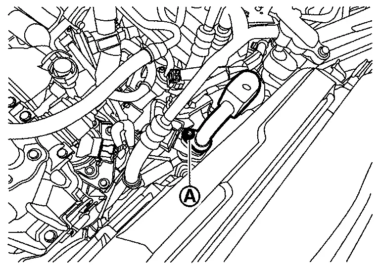
Remove low pressure refrigerant channel switching valve and high-pressure flexible pipe assembly as a set from Nissan Ariya vehicle.
Remove mounting bolt and then disconnect high-pressure flexible pipe assembly from low pressure refrigerant channel switching valve.
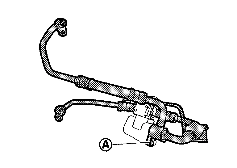
INSTALLATION
Note the following items, and then install in the reverse order of removal.
Disassembly & Assembly
DISASSEMBLY
Peel foam seal.
Remove sensor clip, and then remove condenser discharge refrigerant temperature sensor from high-pressure flexible pipe.
ASSEMBLY
Note the following items, and then assemble in the reverse order of disassembly.
Low-Pressure Refrigerator Pipe Assembly Nissan Ariya SUV
Removal & Installation
REMOVAL
Use a refrigerant collecting equipment (for HFO-1234yf) to discharge the refrigerant. Refer to Recycle Refrigerant.
Remove high voltage power delivery assembly. Refer to HIGH VOLTAGE POWER DELIVERY ASSEMBLY : Removal & Installation.
Disconnect high-pressure cooler pipe assembly from low-pressure refrigerator pipe assembly. Refer to Removal & Installation.
Disconnect evaporator discharge refrigerant temperature sensor harness connector .

Remove stay mounting nut of low-pressure refrigerator pipe assembly.
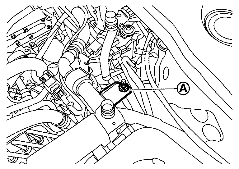
Remove mounting bolt , and then disconnect low-pressure refrigerator pipe assembly from evaporator.
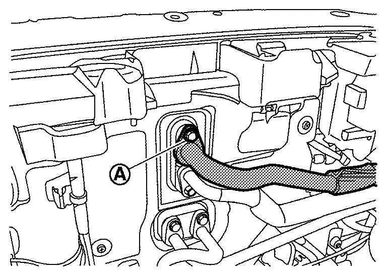
Remove mounting bolt , and then disconnect low-pressure refrigerator pipe assembly from Accumulator assembly.

Remove low-pressure refrigerator pipe assembly from Nissan Ariya vehicle.
INSTALLATION
Note the following items, and then install in the reverse order of removal.
Disassembly & Assembly
DISASSEMBLY
Remove evaporator discharge refrigerant temperature sensor.Remove the harness fixing tape. Peel foam seal. Remove sensor clip, and then remove sensor part from low-pressure refrigerator pipe 1. Disengage harness connector fixing clip of evaporator discharge refrigerant temperature sensor from bracket of low-pressure refrigerator pipe 1.
Remove mounting bolt, and then remove low-pressure refrigerator pipe 1 from evaporator pressure regulator.
Remove mounting bolt, and then remove low-pressure refrigerator pipe 2 from evaporator pressure regulator.
ASSEMBLY
Note the following items, and then assemble in the reverse order of disassembly.
Cooler Pipe a Nissan Ariya 1st generation
Removal & Installation
REMOVAL
Use a refrigerant collecting equipment (for HFO-1234yf) to discharge the refrigerant. Refer to Recycle Refrigerant.
Refer to accumulator assembly removal procedure 2 to 8 and remove radiator, condenser, radiator fan, accumulator assembly, high-pressure flexible pipe assembly and cooler pipe A and B together. Refer to Removal & Installation.
Disconnect high-pressure flexible pipe assembly from cooler pipe A. Refer to Removal & Installation.
Remove mounting bolt , and then disconnect cooler pipe A from condenser.
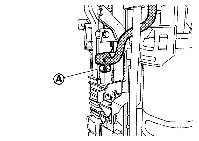
INSTALLATION
Note the following items, and then install in the reverse order of removal.
Accumulator Assembly Nissan Ariya 2026
Removal & Installation
REMOVAL
Use a refrigerant collecting equipment (for HFO-1234yf) to discharge the refrigerant. Refer to Recycle Refrigerant.
Remove low-pressure refrigerator pipe assembly. Refer to Removal & Installation.
Disconnect high-pressure cooler pipe assembly from cooler pipe B. Refer to Removal & Installation.
Disconnect low-pressure flexible hose from Accumulator assembly. Refer to Removal & Installation.
Disconnect high-pressure flexible pipe assembly from high-pressure cooler pipe assembly. Refer to Removal & Installation.
Disconnect condenser discharge refrigerant temperature sensor harness connector and high pressure refrigerant channel switching valve harness connector .
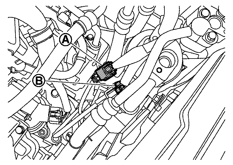
Disengage harness fixing clip from bracket of accumulator.
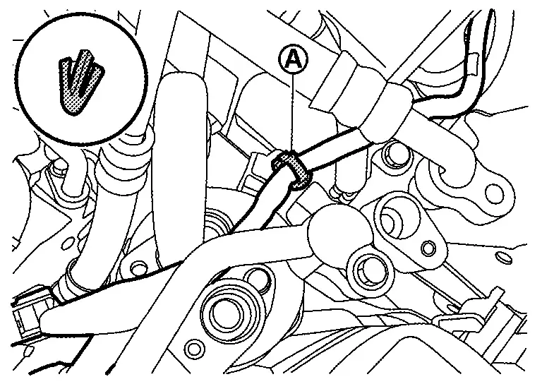
Remove radiator, condenser, radiator fan, accumulator assembly, high-pressure flexible pipe assembly and cooler pipe A, B as a set from Nissan Ariya vehicle. Refer to RADIATOR : Removal & Installation.
Remove cooler pipe A from condenser. Refer to Removal & Installation.
Remove accumulator assembly mounting bolts .
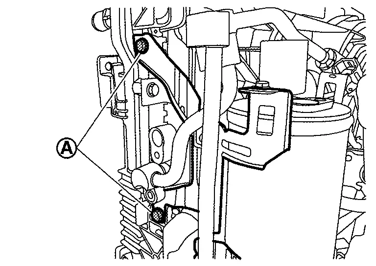
Remove accumulator assembly fixing screws .

Remove accumulator assembly from radiator and radiator fan.
Remove High-pressure flexible pipe assembly from accumulator assembly. Refer to Removal & Installation.
INSTALLATION
Note the following items, and then install in the reverse order of removal.
Disassembly & Assembly
DISASSEMBLY
Disengage harness connector fixing clip of low pressure refrigerant channel switching valve from bracket.
Remove mounting bolt, and then remove low pressure refrigerant channel switching valve from low-pressure pipe.
Remove mounting bolt, and then remove low-pressure pipe from accumulator.
Loosen mounting bolt , and then remove accumulator from bracket.
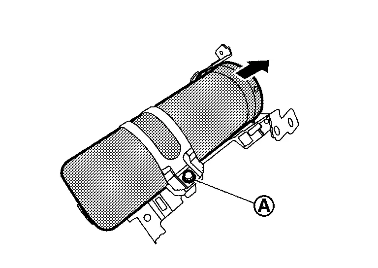
ASSEMBLY
Note the following items, and then assemble in the reverse order of disassembly.
Refrigerant Pressure Sensor Nissan Ariya: FE0
Removal & Installation
REMOVAL
Use a refrigerant collecting equipment (for HFO-1234yf) to discharge the refrigerant. Refer to Recycle Refrigerant.
Disconnect refrigerant pressure sensor harness connector.
Clean refrigerant pressure sensor and its surrounding area, and then remove dust and rust from refrigerant pressure sensor.
Use a adjustable wrench or other tool to hold the refrigerant pressure sensor mounting block, and then remove the refrigerant pressure sensor from high-pressure pipe.
INSTALLATION
Note the following items, and then install in the reverse order of removal.