System Description

In this manual: System Description
How to Use This Manual — 1Precautions — 1Preparation — 1Vehicle Information — 1Basic Inspection — 1Preparation. Commercial Service Tools Or/and Repair Part — 1Description — 1Component Parts — 1System — 1Diagnosis System (vcm) — 1Ecu Diagnosis Information. Vcm — 1Ev Control System — 1Ev/hev (vcm) — 1Component Parts /circuit Diagnosis — 1Ev Control System — 1Periodic Maintenance. Ev System Warning Lamp — 1Removal and Installation. Vcm — 1Traction Motor System :: Front Traction Motor — 1Preparation — 1Description — 4Basic Inspection — 2Dtc Diagnosis — 2Component Parts /circuit Diagnosis — 1Traction Motor System :: Rear Traction Motor — 1Description — 4Basic Inspection — 2Dtc Diagnosis — 2Component Parts /circuit Diagnosis — 1Removal and Installation — 1Ev Battery System :: 66kwh Li-Ion Battery — 1Description — 4Basic Inspection — 2Dtc Diagnosis — 2Component Parts /circuit Diagnosis — 1Removal and Installation — 1Disassembly and Assembly — 2Service Data — 1Ev Battery System :: 91kwh Li-Ion Battery — 1Description — 4Basic Inspection — 2Dtc Diagnosis — 2Component Parts /circuit Diagnosis — 1Removal and Installation — 1Disassembly and Assembly — 1Service Data — 2Preparation. Vehicle Charging System — 1Vehicle Charging System :: Description — 1Component Parts — 2System — 1Diagnosis System (on-Board Charger) — 1Diagnosis System (dc/dc Converter) — 1Ecu Diagnosis Information — 1Vehicle Charging System — 1Charger/pd Module (on-Board Charger) — 1Cplc (cplc) — 1Dcdc (dc/dc Converter) — 1Component Parts/circuit Diagnosis — 1Symptom Diagnosis — 1Evse Inspection — 1Periodic Maintenance — 1Removal and Installation — 1Disassembly and Assembly — 1Preparation. High Voltage Cooling System — 1Description — 1Symptom Diagnosis. Overheating Cause Analysis — 1Periodic Maintenance — 1Coolant — 1Removal and Installation — 1Radiator — 1Service Data — 1Removal and Installation. Accelerator Control System — 1Reduction Gear: Re1f62a — 1Removal and Installation — 1Transaxle & Transmission :: Electric Shift — 1Description — 3Basic Inspection — 2Dtc Diagnosis — 2Component Parts /circuit Diagnosis — 1Removal and Installation — 1Rear Final Drive: Rn1r62a — 1Removal and Installation — 1Preparation. Front Axle System — 1Symptom Diagnosis. Noise, Vibration and Harshness (nvh) Troubleshooting — 1Periodic Maintenance — 1Removal and Installation — 1Service Data. Front Drive Shaft — 12wd — 14wd — 1Periodic Maintenance — 1Removal and Installation — 1Preparation. Front Suspension System — 1Symptom Diagnosis. Noise, Vibration and Harshness (nvh) Troubleshooting — 1Periodic Maintenance — 1Removal and Installation — 1Service Data — 1Symptom Diagnosis. Noise, Vibration and Harshness (nvh) Troubleshooting — 1Periodic Maintenance — 1Removal and Installation — 1Service Data — 1Preparation. Road Wheels & Tires System — 1Description — 1System — 1Ecu Diagnosis Information. Bcm (body Control Module) — 1Tpms — 1Dtc/circuit Diagnosis — 1Symptom Diagnosis — 1Periodic Maintenance. Road Wheels & Tires — 1Removal and Installation — 1Service Data — 1Preparation. Brake System — 1System Description — 1Component Parts — 1Ecu Diagnosis Information. Electrically-Driven Intelligent Brake Unit — 1Basic Inspection — 1Dtc/circuit Diagnosis — 1Symptom Diagnosis — 1Periodic Maintenance — 1Removal and Installation — 1Service Data — 1Preparation. Parking Brake System — 1System Description — 1Component Parts — 1System — 1Ecu Diagnosis Information. Abs Actuator and Electric Unit (control Unit) — 1Basic Inspection. Diagnosis and Repair Work Flow — 1Component Parts /circuit Diagnosis — 1Symptom Diagnosis — 1Removal and Installation — 1Brake Control System :: With Vdc — 1System Description — 3Basic Inspection — 2Dtc/circuit Diagnosis — 1Symptom Diagnosis — 2Removal and Installation — 1Brake Control System :: Automatic Brake Hold — 1System Description — 3Component Parts /circuit Diagnosis — 1Removal and Installation — 1Brake Control System :: E-Step — 1System Description — 3Removal and Installation — 1System Description — 1Ecu Diagnosis Information — 1Basic Inspection — 1Symptom Diagnosis — 1Rear Automatic Braking — 1System Description — 1Basic Inspection — 1Preparation. Steering System — 1System Description — 1Component Parts — 1Basic Inspection — 1Dtc/circuit Diagnosis — 1Symptom Diagnosis — 1Periodic Maintenance. Steering Wheel — 1Removal and Installation — 1Service Data — 1System Description — 1Component Parts — 1Steering Control System — 1Ecu Diagnosis Information. Power Steering Control Module — 1Dtc/circuit Diagnosis — 1Component Parts /circuit Diagnosis — 1Symptom Diagnosis — 1Removal and Installation. Power Steering Control Module — 1System Description — 1Removal and Installation — 1System Description — 1System — 1Basic Inspection. Diagnosis and Repair Work Flow — 1Dtc/circuit Diagnosis — 1Symptom Diagnosis — 1Component Parts — 1Basic Inspection — 1Removal and Installation — 1System Description — 1System — 1Ecu Diagnosis Information. Air Bag Diagnosis Sensor Unit — 1Basic Inspection — 1Dtc/circuit Diagnosis — 1Symptom Diagnosis — 1System Description. Description. Ventilation System — 1Removal and Installation — 1Preparation. Preparation — 1System Description — 1Basic Inspection — 1Symptom Diagnosis — 1Removal and Installation — 1Electric Compressor — 1Cooler Pipe and Hose — 1A/c Unit Assembly Cover — 1A/c Unit Assembly — 1Heater & Air Conditioning Control System :: Automatic Air Conditioning — 1System Description — 1Ecu Diagnosis Information — 1Basic Inspection — 2Dtc Diagnosis — 1Symptom Diagnosis — 1Removal and Installation — 2Preparation. Preparation — 1Symptom Diagnosis. Squeak and Rattle Trouble Diagnoses — 1Removal and Installation — 1Preparation. Instrument Panel — 1Component Parts — 1System — 1Ecu Diagnosis Information. Flexible Center Storage Control Module — 1Basic Inspection. Diagnosis and Repair Work Flow — 1Dtc/circuit Diagnosis — 1Symptom Diagnosis — 1Removal and Installation — 1Preparation. Preparation — 1Component Parts — 1System — 1Ecu Diagnosis Information. Driver Lumbar Support Control Module — 1Basic Inspection. Diagnosis and Repair Work Flow — 1Dtc/circuit Diagnosis — 1Symptom Diagnosis — 1Removal and Installation — 1System Description — 1System — 1Ecu Diagnosis Information — 1Basic Inspection — 1Dtc/circuit Diagnosis — 1Symptom Diagnosis — 1Manual Function Does Not Operate — 1Memory Function Does Not Operate — 1Removal and Installation — 1Preparation. Preparation — 1System Description — 1System (intelligent Key System) — 1Diagnosis System (bcm) — 1Ecu Diagnosis Information — 1Basic Inspection — 1Dtc/circuit Diagnosis — 1U2141-87 Can Comm Circuit — 1Power Supply and Ground Circuit — 1Symptom Diagnosis — 1Automatic Back Door Operation Does Not Operate — 1Back Door Does Not Open — 1Door Does Not Lock/unlock with Door Lock and Unlock Switch — 1Removal and Installation — 1Hood — 1Radiator Core Support — 1Charge Port Lid — 1Front Fender — 1Front Door — 1Rear Door — 1Back Door — 1Hood Lock — 1Front Door Lock — 1Rear Door Lock — 1Back Door Lock — 1Outside Key Antenna — 1System Description — 1System — 1Ecu Diagnosis Information. Inverter (front), Inverter (rear), Bcm, Intelligent Key Unit — 1Basic Inspection — 1Dtc/circuit Diagnosis — 1Symptom Diagnosis — 1Preparation — 1Symptom Diagnosis. Squeak and Rattle Trouble Diagnoses — 1Removal and Installation — 1System Description — 1Ecu Diagnosis Information — 1Basic Inspection — 1Dtc/circuit Diagnosis — 1Power Supply and Ground Circuit — 1Symptom Diagnosis — 1Front Passenger Side Power Window Does Not Operate — 1Rear Lh Side Power Window Does Not Operate — 1Rear Rh Side Power Window Does Not Operate — 1Removal and Installation. Power Window Main Switch — 1Preparation. Preparation — 1System Description — 1Ecu Diagnosis Information — 1Basic Inspection — 1Dtc/circuit Diagnosis — 1Power Supply and Ground Circuit — 1Sunroof Switch Assembly — 1Symptom Diagnosis — 1Auto Operation Does Not Operate — 1Removal and Installation — 1Preparation — 1Description — 1Symptom Diagnosis. Squeak and Rattle Trouble Diagnoses — 1Removal and Installation — 1Service Information — 6Repair Information — 1Precaution — 1Preparation — 1Removal and Installation — 1Service Data — 1Preparation. Preparation — 1Component Parts — 1System — 1Ecu Diagnosis Information — 1Wiring Diagram. Door Mirror — 1Basic Inspection. Diagnosis and Repair Work Flow — 1Dtc/circuit Diagnosis — 1Power Supply and Ground Circuit — 1Symptom Diagnosis — 1Removal and Installation — 1Exterior Lighting System :: Led Headlamp — 1System Description — 3Basic Inspection — 1Dtc/circuit Diagnosis — 1Symptom Diagnosis — 1Periodic Maintenance — 1Removal and Installation — 1System Description — 1System — 1Diagnosis System (bcm) — 1Ecu Diagnosis Information. Bcm, Intelligent Key Unit — 1Basic Inspection. Diagnosis and Repair Work Flow — 1Dtc/circuit Diagnosis — 1Symptom Diagnosis. Interior Lighting System Symptom — 1Removal and Installation — 1Service Data. Bulb Specifications — 1System Description — 1System — 1Ecu Diagnosis Information. Bcm, Ipdm E/r — 1Basic Inspection. Diagnosis and Repair Work Flow — 1Dtc/circuit Diagnosis — 1Symptom Diagnosis — 1Removal and Installation — 1System Description — 1Ecu Diagnosis Information. Bcm — 1Basic Inspection. Diagnosis and Repair Work Flow — 1Dtc/circuit Diagnosis — 1Symptom Diagnosis — 1Removal and Installation — 1Preparation. Preparation — 1Removal and Installation. Horn — 1Preparation. Commercial Service Tools Or/and Repair Part — 1System Description — 1Component Parts — 1Ecu Diagnosis Information. Approaching Vehicle Sound for Pedestrians (vsp) Control Unit — 1Approaching Vehicle Sound for Pedestrians (vsp) — 1Vsp [approaching Vehicle Sound for Pedestrians (vsp) Control Unit] — 1Approaching Vehicle Sound for Pedestrians (vsp) System — 1Removal and Installation — 1Removal and Installation — 1Wireless Charger — 1System Description — 1Basic Inspection — 1Dtc/circuit Diagnosis — 1Removal and Installation — 1Component Parts — 1System — 1Diagnosis System (bcm) — 1Ecu Diagnosis Information. Bcm — 1Basic Inspection — 1Dtc/circuit Diagnosis — 1Symptom Diagnosis — 1Removal and Installation — 1Can Fundamental — 1Description — 1Trouble Diagnosis — 1Can (controller Area Network) — 1Description — 1
~6min read
  • Component Parts
  • System
  • Diagnosis System (wireless Charger Unit)

Component Parts Nissan Ariya

Component Parts Location

Wireless charger unit Wireless charger indicator
Center console finisher

Wireless charger unit

FUNCTIONS WITHIN THE SYSTEM

Wireless charger unit controls wireless charger system.

INDIVIDUAL FUNCTIONS WITHIN THE SYSTEM

Electromagnetic inductive charging is adopted; which allows Qi-Certified devices to be charged without using a cable.
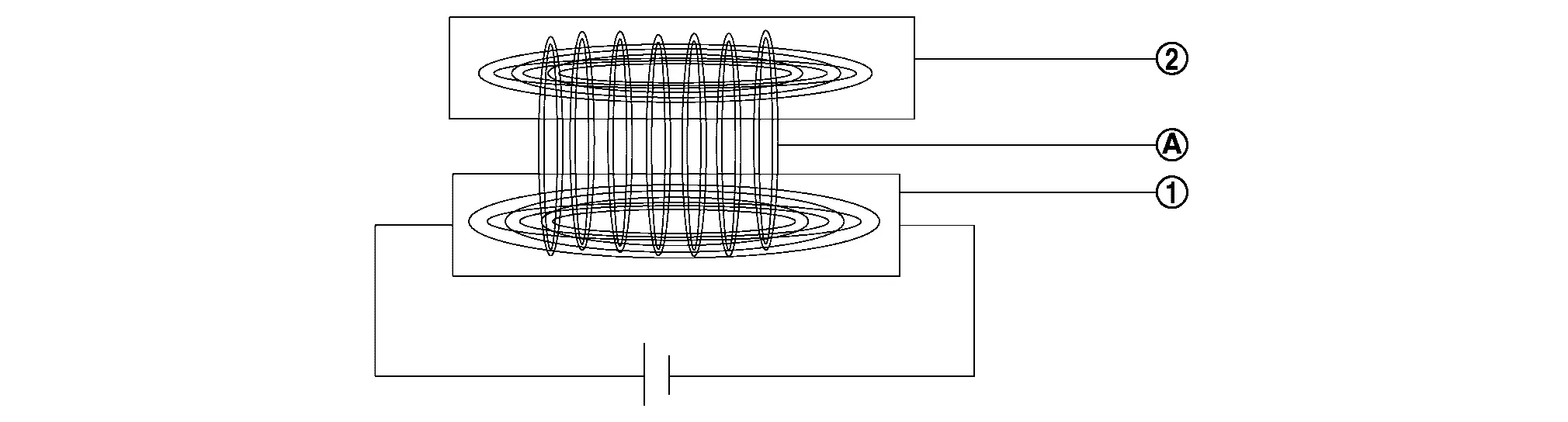
Wireless charger unit Qi-Certified devices
Magnetic field

INDIVIDUAL OPERATION

Refer to System Description.

PARTS LOCATION

The wireless charger unit is mounted on the center console.

Refer to Component Parts Location.

Wireless charger indicator

FUNCTIONS WITHIN THE SYSTEM

Wireless charger indicator shows the status of wireless charger system.
INDIVIDUAL FUNCTIONS WITHIN THE SYSTEM

The integrated green and orange LED lights on/off by the signals transmitted from wireless charger unit.

Wireless charger unit Wireless charger indicator

INDIVIDUAL OPERATION

Refer to System Description.

PARTS LOCATION

Wireless charger indicator is installed on center console finisher.

Refer to Component Parts Location.

System Nissan Ariya SUV

System Description

SYSTEM DIAGRAM
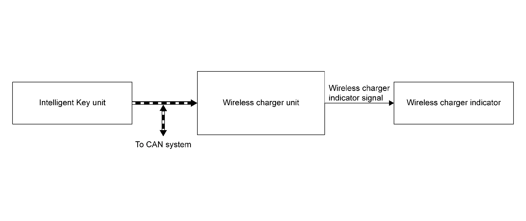
Parts nameDescription
Wireless charger unit Refer to Wireless charger unit.
Wireless charger indicator Refer to Wireless charger indicator.
Intelligent Key unit Transmits the charge stop request signal

CAN Communication

Wireless charger unit input signal
Transmit unitSignal name
Intelligent Key unit Charging stop request signal

DESCRIPTION

  • Wireless charger starts charging automatically by putting Qi-certified devices on charging pad of center console when power switch is ON.

  • Wireless charger indicator shows the charging status of electronic devices and malfunctions of wireless charger by lighting the LED.

IndicatorExplanation
Orange ON Electronic device is charging
Green ON* Electronic device fully charged

Orange blinking

(Indicator turn OFF after 8 sec.)
  • Metallic objects are detected on charging pad

  • Temperature of wireless charger unit goes above 65℃ (149˚F)

  • DTC detected of wireless charger unit

*Depending on electronic device, the wireless charger indicator may remain orange when reaching full charge.

Specifications
Certified Qi
Output wattage 15 W

Operating Conditions

The wireless charger operates when following conditions are all satisfied.

  • Power switch ON

  • Except for the condition of deactivation

Condition of Deactivation

The wireless charger stops operating when one of following conditions is satisfied.

  • When any foreign objects* are detected on the charging pad.

  • When an electronic device is connected to USB cable and starts charging.

  • When Intelligent Key unit is communicating with Intelligent Key.

  • When wireless charger unit is temporarily in high temperature condition [65℃ (149˚F) and more]

  • When DTC is detected

*: Metals (accessories, coins), credit cards, Intelligent Key, etc.

Fail-safe

DTC

Display contents of CONSULT
Fail-safe condition
B1B00-08 CAN communication Wireless charger unit does not work
B1B01-1C Wireless charger unit
B1B02-1D Wireless charger unit
B1B03-49 Wireless charger unit
U0079-00 Control module communication Bus G Off
U214F-87 CAN communication error (BCM)
U2118-87 CAN communication error (Intelligent Key)
U214E-87 CAN communication error (combination meter)
U215B-87 CAN communication error (IPDM E/R)
U2148-87 CAN communication error (brake control unit)

Diagnosis System (wireless Charger Unit) Nissan Ariya SUV

Consult function

APPLICATION ITEMS

CONSULT performs the following functions via the communication with the wireless charger unit.

Diagnosis modeDescription
Self Diagnostic Result Display DTC which wireless charger unit memorizes.
Data Monitor The wireless charger unit input/output data is displayed in real time.
Active Test Transmits a drive signal to check the operation.
Work Support Enables wireless charger unit reset and write VIN data.
ECU Identification The part number of wireless charger unit can be checked.
Replace ECU

SELF DIAGNOSTIC RESULT

Refer to DTC Index.

DATA MONITOR

Monitored itemUnitDescription
Internal temperature ℃ Monitors the temperature inside the wireless charger unit.
Object detected Initial/Yes/No/Inactive Monitors the detecting status of object put on the wireless charger.
Receiver detected UNAVAILABLE/Yes/No/Inactive Monitors the detecting status of receiver (such as smart phones).
Foreign object detected UNAVAILABLE/Yes/No/Inactive Monitors if foreign objects are detected on the wireless charger.
Charger power status UNAVAILABLE/Yes/No/Inactive Monitors the start-up status of the wireless charger.
Charging State UNAVAILABLE/No/Low/Mid/Inactive Monitors the wireless charging status.
Hardware version Unknown/v1.1/v1.2/v1.3/v1.4/v1.5/v1.6/v1.7/v1.8/v1.9/v2.0/v2.1/v2.2/v2.3/v2.4/v2.5/Inactive Monitors the hardware version.
Receiver IC chip ID - Monitors the IC chip ID of receiver (such as smart phones).
Receiver IC chip manufacturer Unknown/Samsung/LGE/Nokia/motorola/Apple/Others Monitors the manufacturer of receiver (such as smart phones).
Receiver Qi version Unknown/1.0/1.1/1.2/Other/Inactive Monitors QI version of receiver (such as smart phones).
Voltage of charging coil V Monitors the voltage of charging coil.
Current of charging coil A Monitors the electric current of charging coil.
Input voltage V Monitors the input voltage in charging coil.
Input current of charging coil A Monitors the input current in charging coil.
Charging power consumption W Monitors the electric current consumption of the wireless charger.
Receive power (receiver side) W Monitors the electric current consumption of the transmitter and receiver (such as smart phones).
Power loss (charger - receiver) W Monitors power loss of the wireless charger unit and receiver (such as smart phones).
Charging Time min Monitors charging time.
Disconnection of charging coil UNAVAILABLE/Yes/No/Inactive Monitors the open circuit of coil inside the wireless charger unit.
Memory error UNAVAILABLE/Yes/No/Inactive Monitors the memory errors of the wireless charger unit.
Reason of stop charging Charge complete/Type2/Type4/Type6 Monitors the reason of stopping wireless charging.
Charge stop request No/Stop/Inactive Monitors the charge stop request signal from Intelligent Key unit.
LED (Orange) UNAVAILABLE/Off/On/Inactive Status of LED (Orange) powered from wireless charger.
LED (green) UNAVAILABLE/Off/On/Inactive Status of LED (Green) powered from the wireless charger.
Firmware Version Unknown/v1.1/v1.2/v1.3/v1.4/v1.5/v1.6/v1.7/v1.8/v1.9/v2.0/v2.1/v2.2/v2.3/v2.4/v2.5/Inactive Monitors the firmware version.

ACTIVE TEST

Monitor ItemDescription
LED (green) This function able to check wireless charger indicator (green).
LED (Orange) This function able to check wireless charger indicator (Orange).
Battery charging This function able to check wireless charging.

WORK SUPPORT

Monitor ItemDescription
WRITE VIN Write VIN data in wireless charger unit.
Reset Reset the wireless charger unit.

ECU IDENTIFICATION

Displays TCU part number and various information.