Component Parts /circuit Diagnosis
- Power Supply and Ground Circuit [inverter (rear)]
- Rear Traction Motor Insulation Resistance Check
- Rear Traction Motor Stator Coil
- Rear Traction Motor Rotor Coil
- Rear Traction Motor Resolver
- Rear Traction Motor Oil Pump
- Traction Motor Oil Pump Relay
Power Supply and Ground Circuit [inverter (rear)] Nissan Ariya: FE0
Diagnosis Procedure
INSPECTION OF THE HARNESS CONNECTOR
Power switch OFF.
Check mating conditions of the harness connector for the inverter (rear).
Is the inspection result normal?
YES>>GO TO 2.
NO>>Repair or replace the malfunctioning parts.
INSPECTION OF THE CONNECTOR TERMINAL
Disconnect the harness connector of the inverter (rear).
Check the inverter (rear) connector for water intrusion, or damage or corrosion of the terminals.
Is the inspection result normal?
YES>>GO TO 3.
NO>>Repair or replace the malfunctioning parts.
INSPECTION OF 12V BATTERY POWER SUPPLY CIRCUIT 1
Check the voltage between the harness connector of the inverter (rear) and the body ground.
| + | − | Voltage | |
|---|---|---|---|
| Inverter (rear) | |||
| Connector | Terminal | ||
| B297 | 18 | Body ground | 9 - 16 V |
| 28 | |||
Is the inspection result normal?
YES>>GO TO 5.
NO>>GO TO 4.
INSPECTION OF 12V BATTERY POWER SUPPLY CIRCUIT 2
Inspect the following items:
Disconnection or short circuit in the wiring harness between the 12V battery and the inverter (rear).
Battery
10A fuse (#93)
Repair or replace the malfunctioning parts.
INSPECTION OF POWER SWITCH CIRCUIT 1
Power switch ON.
Check the voltage between the harness connector of the inverter (rear) and the body ground.
+ − Voltage Inverter (rear) Connector Terminal B297 30 Body ground 9 - 16 V
Is the inspection result normal?
YES >>GO TO 9.
NO>>GO TO 6.
INSPECTION OF POWER SWITCH CIRCUIT 2
Power switch OFF.
Disconnect the IPDM E/R harness connector.
Check continuity between the IPDM E/R harness connector and inverter (rear) harness connector.
IPDM E/R Inverter (rear) Continuity Connector Terminal Connector Terminal E40 25 B297 30 Existed
Is the inspection result normal?
YES>>GO TO 7.
NO>>Repair or replace the malfunctioning parts.
INSPECTION OF POWER SWITCH CIRCUIT 3
Check continuity between the IPDM E/R harness connector and body ground.
| IPDM E/R | − | Continuity | |
|---|---|---|---|
| Connector | Terminal | ||
| E40 | 25 | Body ground | No existed |
Is the inspection result normal?
YES>>GO TO 8.
NO>>Repair or replace the malfunctioning parts.
INSPECTION OF POWER SWITCH CIRCUIT 4
Inspect the following items:
Disconnection or short circuit in the wiring harness between the power switch and IPDM E/R
IPDM E/R
5A fuse (#144)
Repair or replace the malfunctioning parts.
INSPECTION OF THE GROUND CIRCUIT FOR THE INVERTER (REAR)
Check continuity between the harness connector of the inverter (rear) and the body ground.
| Inverter (rear) | − | Continuity | |
|---|---|---|---|
| Connector | Terminal | ||
| B297 | 4 | Body ground | Existed |
| 14 | |||
Is the inspection result normal?
YES>>Perform the troubleshoot simulation test. Refer to Intermittent Incident.
NO>>Repair or replace the malfunctioning parts.
Rear Traction Motor Insulation Resistance Check Nissan Ariya first Gen
Component Inspection
PRECONDITIONING
Disconnect high voltage circuit. Refer to HOW TO DISCONNECT HIGH VOLTAGE : Precautions.
Check voltage in high voltage circuit. Refer to CHECK VOLTAGE IN HIGH VOLTAGE CIRCUIT : Precautions.
GO TO 2.
CHECK OF THE INSULATION RESISTANCE VALUE AT THE REAR TRACTION MOTOR
Remove the rear traction motor. Refer to Removal and Installation.
Inspect the insulation resistance in the rear traction motor with an insulation resistance tester (multi-tester).
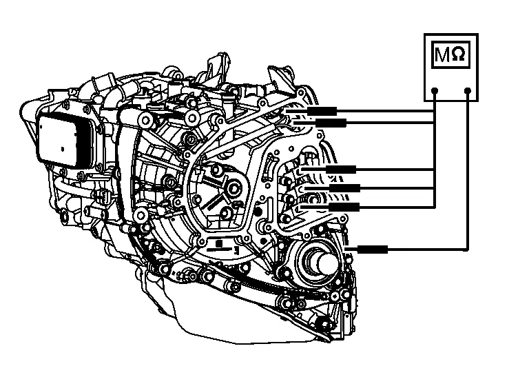
Rear traction motor Ground Resistance Terminal U-phase Rear traction motor case 1 GΩ or more V-phase W-phase Ex+ Ex-
Is the inspection result normal?
YES>>INSPECTION END
NO>>Replace the rear traction motor. Refer to Removal and Installation.
Rear Traction Motor Stator Coil Nissan Ariya 2023
Component Inspection
CHECK OF RESISTANCE VALUE AT THE REAR TRACTION MOTOR STATOR COIL
Use milli-ohm tester to inspect the resistance value in the stator coil for the rear traction motor.
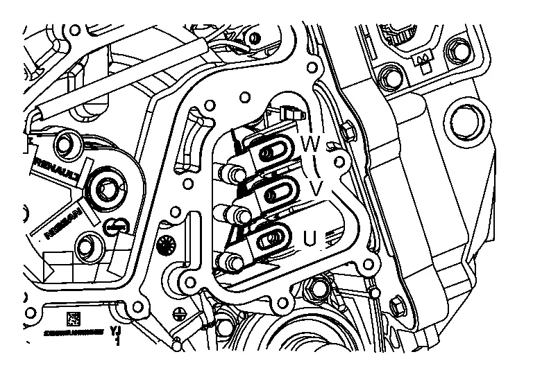
| Rear traction motor | Resistance* | |
|---|---|---|
| Terminal | ||
| U-phase | V-phase | 15.36 – 16.64 mΩ |
| V-phase | W-phase | |
| W-phase | U-phase | |
*: This resistance value is measured in an environment where the outside temperature is 20 °C. Use the following formula and convert the resistance value by inputting the outside temperature at the time of the inspection.
Calculation Formula
R20 = R / [1 + 0.00393 × (T - 20)]
R20: Resistance value (mΩ) when the outside temperature is 20 °C
R: Resistance value (mΩ) for the outside temperature at the time of the inspection
T: Outside temperature at the time of the inspection
Is the inspection result normal?
YES>>INSPECTION END
NO>>The stator coil has malfunctioned. Replace the rear traction motor. Refer to Removal and Installation.
Rear Traction Motor Rotor Coil Nissan Ariya 2023
Component Inspection
CHECK OF THE ROTOR COIL RESISTANCE VALUE AT THE REAR TRACTION MOTOR
Check the rotor coil resistance value at the rear traction motor.
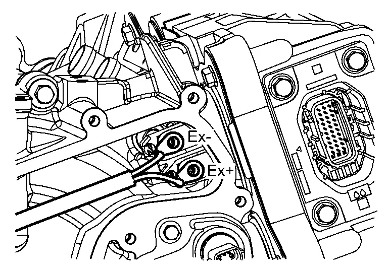
| Rear traction motor | Resistance | |
|---|---|---|
| Terminal | ||
| Ex+ | Ex- | 5.80 – 6.54 Ω |
Calculation Formula
R20 = R / [1 + 0.00393 × (T - 20)]
R20: Resistance value (Ω) when the outside temperature is 20 °C
R: Resistance value (Ω) for the outside temperature at the time of the inspection
T: Outside temperature at the time of the inspection
Is the inspection result normal?
YES>>INSPECTION END
NO>>The rotor coil has malfunctioned. Replace the rear traction motor. Refer to Removal and Installation.
Rear Traction Motor Resolver Nissan Ariya 2023
Diagnosis Procedure
INSPECTION OF THE HARNESS CONNECTOR 1
Turn OFF the power switch.
Check mating conditions of the harness connector for the inverter (rear).
Is the inspection result normal?
YES>>GO TO 2.
NO>>Repair or replace the malfunctioning parts.
INSPECTION OF THE HARNESS CONNECTOR 2
Check mating conditions of the harness connector for the rear traction motor.
Is the inspection result normal?
YES>>GO TO 3.
NO>>Repair or replace the malfunctioning parts.
INSPECTION OF THE CONNECTOR TERMINALS 1
Disconnect the harness connector of the inverter (rear).
Check the inverter (rear) connector for water intrusion, or damage or corrosion of the terminals.
Is the inspection result normal?
YES>>GO TO 4.
NO>>Repair or replace the malfunctioning parts.
INSPECTION OF THE CONNECTOR TERMINALS 2
Disconnect the harness connector of the rear traction motor.
Check the wiring harness connector of the rear traction motor for water intrusion, or damage or corrosion of the terminals.
Is the inspection result normal?
YES>>GO TO 5.
NO >>Repair or replace the malfunctioning parts.
INSPECTION OF THE REAR TRACTION MOTOR RESOLVER CIRCUIT 1
Check the resistance between the harness connector of the inverter (rear) and the body ground.
| Inverter (rear) | ― | Resistance | |
|---|---|---|---|
| Connector | Terminal | ||
| B297 | 12 | Body ground | 100 kΩ or more |
| 13 | |||
| 21 | |||
| 22 | |||
| 23 | |||
| 24 | |||
Is the inspection result normal?
YES>>GO TO 6.
NO>>Repair or replace the malfunctioning parts.
INSPECTION OF THE REAR TRACTION MOTOR RESOLVER CIRCUIT 2
Inspect the resistance between the wiring harness connector for the inverter (rear) and the wiring harness connector for the rear traction motor.
Inverter (rear) Rear traction motor Resistance Connector Terminal Connector Terminal B297 12 B296 3 1 Ω or less 13 2 21 5 22 4 23 1 24 6 Inspect the wiring harness for a short circuit.
Inverter (rear) Resistance Connector Terminal B297 12 13 100 kΩ or more 21 22 23 24 13 21 22 23 24 21 22 23 24 22 23 24 23 24
Is the inspection result normal?
YES>>GO TO 7.
NO>>Repair or replace the malfunctioning parts.
INSPECTION OF THE REAR TRACTION MOTOR RESOLVER
Inspect the rear traction motor resolver. Refer to Component Inspection.
Is the inspection result normal?
YES>>Replace the inverter (rear). Refer to Removal and Installation.
NO>>Repair or replace the malfunctioning parts.
Component Inspection
INSPECTION OF THE REAR TRACTION MOTOR RESOLVER
Disconnect the harness connector of the rear traction motor.
Check the resistance between terminals in the rear traction motor connector.
| Rear traction motor | Resistance | |
|---|---|---|
| Terminal | ||
| 2 | 3 | 34.6 - 42.4 Ω |
| 4 | 5 | 37.6 - 46.0 Ω |
| 1 | 6 | 8.5 - 12.7 Ω |
Is the inspection result normal?
YES>>INSPECTION END
NO>>The rear traction motor resolver has malfunctioned. Replace the rear traction motor. Refer to Removal and Installation.
Rear Traction Motor Oil Pump Nissan Ariya 2026
Diagnosis Procedure
INSPECTION OF THE HARNESS CONNECTOR 1
Turn OFF the power switch.
Check mating conditions of the harness connector for the inverter (rear).
Is the inspection result normal?
YES>>GO TO 2.
NO>>Repair or replace the malfunctioning parts.
INSPECTION OF THE HARNESS CONNECTOR 2
Check mating conditions of the harness connector for the rear traction motor oil pump.
Is the inspection result normal?
YES>>GO TO 3.
NO>>Repair or replace the malfunctioning parts.
INSPECTION OF THE CONNECTOR TERMINALS 1
Disconnect the harness connector of the inverter (rear).
Check the inverter (rear) connector for water intrusion, or damage or corrosion of the terminals.
Is the inspection result normal?
YES>>GO TO 4.
NO>>Repair or replace the malfunctioning parts.
INSPECTION OF THE CONNECTOR TERMINALS 2
Disconnect the harness connector of the rear traction motor oil pump.
Check the wiring harness connector of the rear traction motor oil pump for water intrusion, or damage or corrosion of the terminals.
Is the inspection result normal?
YES>>GO TO 5.
>>Repair or replace the malfunctioning parts.
INSPECTION OF THE REAR TRACTION MOTOR OIL PUMP POWER SUPPLY
Turn ON the power switch, or set to READY.
Check the voltage between the harness connector of the rear traction motor oil pump and the body ground.
+ − Voltage Rear traction motor oil pump Connector Terminal B298 4 Body ground 9 - 16 V
Is the inspection result normal?
YES >>GO TO 14.
NO>>GO TO 6.
INSPECTION OF THE OIL PUMP POWER SUPPLY CIRCUIT IN THE REAR TRACTION MOTOR 1
Inspect the 15A fuse (#96).
Remove the traction motor oil pump relay.
Check the continuity between the wiring harness connector for the traction motor oil pump relay and the wiring harness connector for the rear traction oil pump.
Traction motor oil pump relay Rear traction motor oil pump Continuity Connector Terminal Connector Terminal E128 5 B298 4 Existed
Is the inspection result normal?
YES>>GO TO 7.
NO>>Repair or replace the malfunctioning parts.
INSPECTION OF THE OIL PUMP POWER SUPPLY CIRCUIT IN THE REAR TRACTION MOTOR 2
Check the continuity between the harness connector of the traction motor oil pump and the body ground.
| Rear traction motor oil pump | − | Continuity | |
|---|---|---|---|
| Connector | Terminal | ||
| B298 | 4 | Body ground | Not existed |
Is the inspection result normal?
YES>>GO TO 8.
NO>>Repair or replace the malfunctioning parts.
INSPECTION OF THE TRACTION MOTOR OIL PUMP RELAY 1
Check the voltage between the harness connector of the traction motor oil pump relay and the body ground.
| + | − | Voltage | |
|---|---|---|---|
| Traction motor oil pump relay | |||
| Connector | Terminal | ||
| E128 | 2 | Body ground | 9 – 16 V |
| 3 | |||
Is the inspection result normal?
YES>>GO TO 10.
NO>>GO TO 9.
INSPECTION OF THE TRACTION MOTOR OIL PUMP RELAY 2
Inspect the following items:
Disconnection or short circuit between the 12V battery and the traction motor oil pump relay
10A fuse (#90)
30A fusible link (#P)
Repair or replace the malfunctioning parts.
INSPECTION OF THE TRACTION MOTOR OIL PUMP RELAY
Inspect the traction motor oil pump relay. Refer to Component Inspection.
Is the inspection result normal?
YES>>GO TO 11.
NO>>Repair or replace the malfunctioning parts.
INSPECTION OF ACTIVATION SIGNAL FOR THE TRACTION MOTOR OIL PUMP RELAY
Install the traction motor oil pump relay.
Check the output signal of VCM connector terminal No. 97. Refer to Physical Values.
Is the inspection result normal?
YES>>GO TO 12.
NO>>Repair or replace the malfunctioning parts.
INSPECTION OF THE ACTIVATION SIGNAL CIRCUIT FOR THE TRACTION MOTOR OIL PUMP RELAY 1
Remove the traction motor oil pump relay.
Disconnect the VCM wiring harness connector.
Check the continuity between the harness connector of the traction motor oil pump relay and the VCM harness connector.
Traction motor oil pump relay VCM Continuity Connector Terminal Connector Terminal E128 1 E48 97 Existed
GO TO 13.
NO>>Repair or replace the malfunctioning parts.
INSPECTION OF THE ACTIVATION SIGNAL CIRCUIT FOR THE TRACTION MOTOR OIL PUMP RELAY 2
Check the continuity between the harness connector of the traction motor oil pump relay and the body ground.
| Traction motor oil pump relay | − | Continuity | |
|---|---|---|---|
| Connector | Terminal | ||
| E128 | 1 | Body ground | Not existed |
Is the inspection result normal?
YES>>Replace the VCM. Refer to VCM : Removal & Installation.
NO>>Repair or replace the malfunctioning parts.
INSPECTION OF THE OIL PUMP GROUND CIRCUIT FOR THE REAR TRACTION MOTOR
Check the continuity between the harness connector of the rear traction motor oil pump and the body ground.
| Rear traction motor oil pump | − | Continuity | |
|---|---|---|---|
| Connector | Terminal | ||
| B298 | 1 | Body ground | Existed |
Is the inspection result normal?
YES>>GO TO 15.
NO>>Repair or replace the malfunctioning parts.
INSPECTION OF THE OIL PUMP COMMUNICATION CIRCUIT FOR THE REAR TRACTION MOTOR 1
Check the resistance between the harness connector of the rear traction motor oil pump and the body ground.
| Rear traction motor oil pump | − | Resistance | |
|---|---|---|---|
| Connector | Terminal | ||
| B298 | 2 | Body ground | 200 kΩ or more |
| 3 | |||
Is the inspection result normal?
YES>>GO TO 16.
NO>>Repair or replace the malfunctioning parts.
INSPECTION OF THE OIL PUMP COMMUNICATION CIRCUIT FOR THE REAR TRACTION MOTOR 2
Check the resistance between the wiring harness connector for the inverter (rear) and the wiring harness connector for the rear traction motor oil pump.
Inverter (rear) Rear traction motor oil pump Resistance Connector Terminal Connector Terminal B297 19 B298 2 1 Ω or less 29 3 Inspect the wiring harness for a short circuit.
Inverter (rear) Rear traction motor oil pump Resistance Connector Terminal Connector Terminal B297 19 B298 3 100 kΩ or more 29 2
Is the inspection result normal?
YES>>GO TO 17.
NO>>Repair or replace the malfunctioning parts.
REPLACEMENT OF THE REAR TRACTION MOTOR
Replace the rear traction motor. Refer to Removal and Installation.
Perform the DTC CONFIRMATION PROCEDURE.
Is a DTC related to the rear traction motor oil pump detected?
YES>>Replace the inverter (rear). Refer to .Removal and Installation.
NO>>INSPECTION END
Traction Motor Oil Pump Relay Nissan Ariya: FE0
Component Inspection
INSPECTION OF THE TRACTION MOTOR OIL PUMP RELAY
Power switch OFF.
Remove the traction motor oil pump relay. Refer to Component Parts Location.
Apply 12V battery voltage between terminals 1 and 2 in the connector of the traction motor oil pump relay.
Check the continuity between terminals 3 and 5 in the connector of the traction motor oil pump relay.
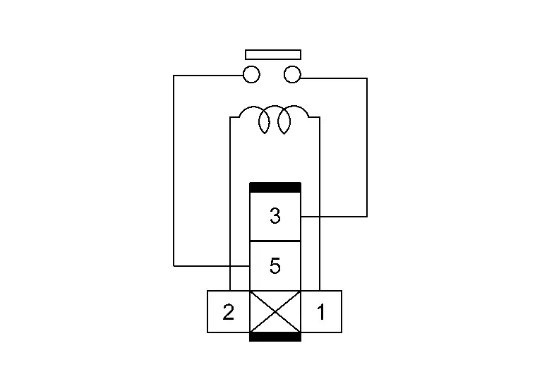
Traction motor oil pump relay Condition Continuity Terminal 3 5 12V battery voltage is applied between terminals 1 and 2. Existed 12V battery voltage is not applied. Not existed
Is the inspection result normal?
YES>>INSPECTION END
NO>>Replace the traction motor oil pump relay.