Vsp [approaching Vehicle Sound for Pedestrians (vsp) Control Unit]

In this manual: Vsp [approaching Vehicle Sound for Pedestrians (vsp) Control Unit]
How to Use This Manual — 1Precautions — 1Preparation — 1Vehicle Information — 1Basic Inspection — 1Preparation. Commercial Service Tools Or/and Repair Part — 1Description — 1Component Parts — 1System — 1Diagnosis System (vcm) — 1Ecu Diagnosis Information. Vcm — 1Ev Control System — 1Ev/hev (vcm) — 1Component Parts /circuit Diagnosis — 1Ev Control System — 1Periodic Maintenance. Ev System Warning Lamp — 1Removal and Installation. Vcm — 1Traction Motor System :: Front Traction Motor — 1Preparation — 1Description — 4Basic Inspection — 2Dtc Diagnosis — 2Component Parts /circuit Diagnosis — 1Traction Motor System :: Rear Traction Motor — 1Description — 4Basic Inspection — 2Dtc Diagnosis — 2Component Parts /circuit Diagnosis — 1Removal and Installation — 1Ev Battery System :: 66kwh Li-Ion Battery — 1Description — 4Basic Inspection — 2Dtc Diagnosis — 2Component Parts /circuit Diagnosis — 1Removal and Installation — 1Disassembly and Assembly — 2Service Data — 1Ev Battery System :: 91kwh Li-Ion Battery — 1Description — 4Basic Inspection — 2Dtc Diagnosis — 2Component Parts /circuit Diagnosis — 1Removal and Installation — 1Disassembly and Assembly — 1Service Data — 2Preparation. Vehicle Charging System — 1Vehicle Charging System :: Description — 1Component Parts — 2System — 1Diagnosis System (on-Board Charger) — 1Diagnosis System (dc/dc Converter) — 1Ecu Diagnosis Information — 1Vehicle Charging System — 1Charger/pd Module (on-Board Charger) — 1Cplc (cplc) — 1Dcdc (dc/dc Converter) — 1Component Parts/circuit Diagnosis — 1Symptom Diagnosis — 1Evse Inspection — 1Periodic Maintenance — 1Removal and Installation — 1Disassembly and Assembly — 1Preparation. High Voltage Cooling System — 1Description — 1Symptom Diagnosis. Overheating Cause Analysis — 1Periodic Maintenance — 1Coolant — 1Removal and Installation — 1Radiator — 1Service Data — 1Removal and Installation. Accelerator Control System — 1Reduction Gear: Re1f62a — 1Removal and Installation — 1Transaxle & Transmission :: Electric Shift — 1Description — 3Basic Inspection — 2Dtc Diagnosis — 2Component Parts /circuit Diagnosis — 1Removal and Installation — 1Rear Final Drive: Rn1r62a — 1Removal and Installation — 1Preparation. Front Axle System — 1Symptom Diagnosis. Noise, Vibration and Harshness (nvh) Troubleshooting — 1Periodic Maintenance — 1Removal and Installation — 1Service Data. Front Drive Shaft — 12wd — 14wd — 1Periodic Maintenance — 1Removal and Installation — 1Preparation. Front Suspension System — 1Symptom Diagnosis. Noise, Vibration and Harshness (nvh) Troubleshooting — 1Periodic Maintenance — 1Removal and Installation — 1Service Data — 1Symptom Diagnosis. Noise, Vibration and Harshness (nvh) Troubleshooting — 1Periodic Maintenance — 1Removal and Installation — 1Service Data — 1Preparation. Road Wheels & Tires System — 1Description — 1System — 1Ecu Diagnosis Information. Bcm (body Control Module) — 1Tpms — 1Dtc/circuit Diagnosis — 1Symptom Diagnosis — 1Periodic Maintenance. Road Wheels & Tires — 1Removal and Installation — 1Service Data — 1Preparation. Brake System — 1System Description — 1Component Parts — 1Ecu Diagnosis Information. Electrically-Driven Intelligent Brake Unit — 1Basic Inspection — 1Dtc/circuit Diagnosis — 1Symptom Diagnosis — 1Periodic Maintenance — 1Removal and Installation — 1Service Data — 1Preparation. Parking Brake System — 1System Description — 1Component Parts — 1System — 1Ecu Diagnosis Information. Abs Actuator and Electric Unit (control Unit) — 1Basic Inspection. Diagnosis and Repair Work Flow — 1Component Parts /circuit Diagnosis — 1Symptom Diagnosis — 1Removal and Installation — 1Brake Control System :: With Vdc — 1System Description — 3Basic Inspection — 2Dtc/circuit Diagnosis — 1Symptom Diagnosis — 2Removal and Installation — 1Brake Control System :: Automatic Brake Hold — 1System Description — 3Component Parts /circuit Diagnosis — 1Removal and Installation — 1Brake Control System :: E-Step — 1System Description — 3Removal and Installation — 1System Description — 1Ecu Diagnosis Information — 1Basic Inspection — 1Symptom Diagnosis — 1Rear Automatic Braking — 1System Description — 1Basic Inspection — 1Preparation. Steering System — 1System Description — 1Component Parts — 1Basic Inspection — 1Dtc/circuit Diagnosis — 1Symptom Diagnosis — 1Periodic Maintenance. Steering Wheel — 1Removal and Installation — 1Service Data — 1System Description — 1Component Parts — 1Steering Control System — 1Ecu Diagnosis Information. Power Steering Control Module — 1Dtc/circuit Diagnosis — 1Component Parts /circuit Diagnosis — 1Symptom Diagnosis — 1Removal and Installation. Power Steering Control Module — 1System Description — 1Removal and Installation — 1System Description — 1System — 1Basic Inspection. Diagnosis and Repair Work Flow — 1Dtc/circuit Diagnosis — 1Symptom Diagnosis — 1Component Parts — 1Basic Inspection — 1Removal and Installation — 1System Description — 1System — 1Ecu Diagnosis Information. Air Bag Diagnosis Sensor Unit — 1Basic Inspection — 1Dtc/circuit Diagnosis — 1Symptom Diagnosis — 1System Description. Description. Ventilation System — 1Removal and Installation — 1Preparation. Preparation — 1System Description — 1Basic Inspection — 1Symptom Diagnosis — 1Removal and Installation — 1Electric Compressor — 1Cooler Pipe and Hose — 1A/c Unit Assembly Cover — 1A/c Unit Assembly — 1Heater & Air Conditioning Control System :: Automatic Air Conditioning — 1System Description — 1Ecu Diagnosis Information — 1Basic Inspection — 2Dtc Diagnosis — 1Symptom Diagnosis — 1Removal and Installation — 2Preparation. Preparation — 1Symptom Diagnosis. Squeak and Rattle Trouble Diagnoses — 1Removal and Installation — 1Preparation. Instrument Panel — 1Component Parts — 1System — 1Ecu Diagnosis Information. Flexible Center Storage Control Module — 1Basic Inspection. Diagnosis and Repair Work Flow — 1Dtc/circuit Diagnosis — 1Symptom Diagnosis — 1Removal and Installation — 1Preparation. Preparation — 1Component Parts — 1System — 1Ecu Diagnosis Information. Driver Lumbar Support Control Module — 1Basic Inspection. Diagnosis and Repair Work Flow — 1Dtc/circuit Diagnosis — 1Symptom Diagnosis — 1Removal and Installation — 1System Description — 1System — 1Ecu Diagnosis Information — 1Basic Inspection — 1Dtc/circuit Diagnosis — 1Symptom Diagnosis — 1Manual Function Does Not Operate — 1Memory Function Does Not Operate — 1Removal and Installation — 1Preparation. Preparation — 1System Description — 1System (intelligent Key System) — 1Diagnosis System (bcm) — 1Ecu Diagnosis Information — 1Basic Inspection — 1Dtc/circuit Diagnosis — 1U2141-87 Can Comm Circuit — 1Power Supply and Ground Circuit — 1Symptom Diagnosis — 1Automatic Back Door Operation Does Not Operate — 1Back Door Does Not Open — 1Door Does Not Lock/unlock with Door Lock and Unlock Switch — 1Removal and Installation — 1Hood — 1Radiator Core Support — 1Charge Port Lid — 1Front Fender — 1Front Door — 1Rear Door — 1Back Door — 1Hood Lock — 1Front Door Lock — 1Rear Door Lock — 1Back Door Lock — 1Outside Key Antenna — 1System Description — 1System — 1Ecu Diagnosis Information. Inverter (front), Inverter (rear), Bcm, Intelligent Key Unit — 1Basic Inspection — 1Dtc/circuit Diagnosis — 1Symptom Diagnosis — 1Preparation — 1Symptom Diagnosis. Squeak and Rattle Trouble Diagnoses — 1Removal and Installation — 1System Description — 1Ecu Diagnosis Information — 1Basic Inspection — 1Dtc/circuit Diagnosis — 1Power Supply and Ground Circuit — 1Symptom Diagnosis — 1Front Passenger Side Power Window Does Not Operate — 1Rear Lh Side Power Window Does Not Operate — 1Rear Rh Side Power Window Does Not Operate — 1Removal and Installation. Power Window Main Switch — 1Preparation. Preparation — 1System Description — 1Ecu Diagnosis Information — 1Basic Inspection — 1Dtc/circuit Diagnosis — 1Power Supply and Ground Circuit — 1Sunroof Switch Assembly — 1Symptom Diagnosis — 1Auto Operation Does Not Operate — 1Removal and Installation — 1Preparation — 1Description — 1Symptom Diagnosis. Squeak and Rattle Trouble Diagnoses — 1Removal and Installation — 1Service Information — 6Repair Information — 1Precaution — 1Preparation — 1Removal and Installation — 1Service Data — 1Preparation. Preparation — 1Component Parts — 1System — 1Ecu Diagnosis Information — 1Wiring Diagram. Door Mirror — 1Basic Inspection. Diagnosis and Repair Work Flow — 1Dtc/circuit Diagnosis — 1Power Supply and Ground Circuit — 1Symptom Diagnosis — 1Removal and Installation — 1Exterior Lighting System :: Led Headlamp — 1System Description — 3Basic Inspection — 1Dtc/circuit Diagnosis — 1Symptom Diagnosis — 1Periodic Maintenance — 1Removal and Installation — 1System Description — 1System — 1Diagnosis System (bcm) — 1Ecu Diagnosis Information. Bcm, Intelligent Key Unit — 1Basic Inspection. Diagnosis and Repair Work Flow — 1Dtc/circuit Diagnosis — 1Symptom Diagnosis. Interior Lighting System Symptom — 1Removal and Installation — 1Service Data. Bulb Specifications — 1System Description — 1System — 1Ecu Diagnosis Information. Bcm, Ipdm E/r — 1Basic Inspection. Diagnosis and Repair Work Flow — 1Dtc/circuit Diagnosis — 1Symptom Diagnosis — 1Removal and Installation — 1System Description — 1Ecu Diagnosis Information. Bcm — 1Basic Inspection. Diagnosis and Repair Work Flow — 1Dtc/circuit Diagnosis — 1Symptom Diagnosis — 1Removal and Installation — 1Preparation. Preparation — 1Removal and Installation. Horn — 1Preparation. Commercial Service Tools Or/and Repair Part — 1System Description — 1Component Parts — 1Ecu Diagnosis Information. Approaching Vehicle Sound for Pedestrians (vsp) Control Unit — 1Approaching Vehicle Sound for Pedestrians (vsp) — 1Vsp [approaching Vehicle Sound for Pedestrians (vsp) Control Unit] — 1Approaching Vehicle Sound for Pedestrians (vsp) System — 1Removal and Installation — 1Removal and Installation — 1Wireless Charger — 1System Description — 1Basic Inspection — 1Dtc/circuit Diagnosis — 1Removal and Installation — 1Component Parts — 1System — 1Diagnosis System (bcm) — 1Ecu Diagnosis Information. Bcm — 1Basic Inspection — 1Dtc/circuit Diagnosis — 1Symptom Diagnosis — 1Removal and Installation — 1Can Fundamental — 1Description — 1Trouble Diagnosis — 1Can (controller Area Network) — 1Description — 1
43steps
~258min
4/5difficulty
Done 0 of 43
  • B2860-87 Vsp Control Unit
  • B2861-87 Vsp Speaker Lh
  • B2863-87 Battery Voltage
  • U0075-00 Vsp Control Unit
  • Power Supply and Ground Circuit
  • Approaching Vehicle Sound for Pedestrians (vsp) Speaker Signal Circuit
  • Approaching Vehicle Sound for Pedestrians (vsp) Speaker

B2860-87 Vsp Control Unit Nissan Ariya 2026

DTC Description

DTC DETECTION LOGIC

DTC No.CONSULT screen termsDTC detection condition
B2860–87 VSP control unit Diagnosis condition When power switch is ON.
Signal (terminal) —
Threshold When detecting error during the initial diagnosis of the CAN controller of VSP control unit.
Diagnosis delay time 2 seconds or more

POSSIBLE CAUSE

VSP control unit.

FAIL-SAFE

  • VSP function stops.

  • Charge sound system does not operate.

Confirmation Procedure

PERFORM DTC CONFIRMATION PROCEDURE

CONSULT

  1. Set Nissan Ariya vehicle to ready and wait for 2 seconds or more.

  2. Select “Self Diagnostic Result” mode of "VSP".

  3. Check if the DTC “B2860–87" is detected in “Self Diagnostic Result” mode of “VSP”.

Is “B2860–87” detected?

YES>>

Refer to DTC Diagnosis Procedure.

NO-1>>

To check malfunction symptom before repair: Refer to Intermittent Incident.

NO-2>>

Confirmation after repair: Inspection End.

DTC Diagnosis Procedure

PERFORM SELF DIAGNOSTIC RESULT

CONSULT

  1. Power switch ON.

  2. Erase “Self Diagnostic Result”.

  3. Perform DTC confirmation procedure again. Refer to DTC Confirmation Procedure.

Is “B2860–87” detected?

YES>>

Replace VSP control unit. Refer to APPROACHING Nissan Ariya Vehicle SOUND FOR PEDESTRIANS (VSP) CONTROL UNIT : Removal & Installation.

NO>>

Inspection End.

B2861-87 Vsp Speaker Lh Nissan Ariya

DTC Description

DTC DETECTION LOGIC

DTC No.CONSULT screen termsDTC detection condition
B2861–87 VSP speaker LH Diagnosis condition When power switch is ON.
Signal (terminal) VSP speaker signal LH
Threshold Abnormal VSP speaker signal is detected
Diagnosis delay time 2 seconds or more

POSSIBLE CAUSE

VSP control unit.

VSP speaker.

FAIL-SAFE

  • VSP function stops.

  • Charge sound system does not operate.

Confirmation Procedure

PERFORM DTC CONFIRMATION PROCEDURE

CONSULT

  1. Power switch ON.

  2. Power switch OFF and wait at least 30 seconds.

  3. Power switch ON and wait at least 30 seconds or more.

  4. Select “Self Diagnostic Result” mode of “VSP”.

  5. Check DTC.

Is DTC "B2861–87" detected?

YES>>

Refer to DTC Diagnosis Procedure.

NO-1>>

To check malfunction symptom before repair: Refer to Intermittent Incident.

NO-2>>

Confirmation after repair: Inspection End.

DTC Diagnosis Procedure

CHECK VSP SPEAKER SIGNAL CIRCUIT

  1. Power switch ON.

  2. Erase DTC.

  3. Check the VSP speaker signal circuit. Refer to Diagnosis Procedure.

Is the inspection result normal?

YES>>

Replace VSP control unit. Refer to APPROACHING Nissan Ariya Vehicle SOUND FOR PEDESTRIANS (VSP) CONTROL UNIT : Removal & Installation.

NO>>

Repair or replace malfunctioning parts.

B2863-87 Battery Voltage Nissan Ariya 2026

DTC Description

DTC DETECTION LOGIC

DTC No.CONSULT screen termsDTC detection condition
B2863–87 Battery voltage Diagnosis condition When power switch is ON.
Signal (terminal) Battery power supply
Threshold Low or high voltage is detected.
Diagnosis delay time —

POSSIBLE CAUSE

  • Battery power supply

FAIL-SAFE

  • VSP system: Function stops due to power supply issue.

  • Speakers inoperative

Confirmation Procedure

PERFORM DTC CONFIRMATION PROCEDURE

CONSULT

  1. Power switch ON.

  2. Select “Self Diagnostic Result” mode of “VSP”.

  3. Check DTC.

Is DTC "B2863–87" detected?

YES>>

Refer to DTC Diagnosis Procedure.

NO>>

To check malfunction symptom before repair. Refer to Intermittent Incident.

DTC Diagnosis Procedure

CHECK VSP CONTROL UNIT POWER SUPPLY AND GROUND CIRCUIT

Check power supply and ground circuit of VSP control unit. Refer to Diagnosis Procedure.

Is the inspection result normal?

YES>>

Replace VSP control unit. Refer to APPROACHING Nissan Ariya Vehicle SOUND FOR PEDESTRIANS (VSP) CONTROL UNIT : Removal & Installation.

NO>>

Repair or replace the malfunctioning parts. Inspection End

U0075-00 Vsp Control Unit Nissan Ariya 1st generation

DTC Description

Description

CAN (Controller Area Network) is a serial communication system for real time application. It is an on-Nissan Ariya vehicle multiplex communication system with high data communication speed and excellent error detectability. Many electronic control units are equipped onto Nissan Ariya vehicles, and each control unit shares information and links with other control units during operation (not independent). In CAN communication, control units are connected with two communication lines (CAN-High line, CAN-Low line) allowing a high rate of information transmission with less wiring. Each control unit transmits/receives data but selectively reads required data only.

CAN Communication Signal Chart. Refer to CAN Communication Signal Chart.

DTC DETECTION LOGIC

DTC No.CONSULT screen termsDTC detection condition
U0075-00 Control module communication bus C off Diagnosis condition When power switch is ON.
Signal (terminal) CAN communication signal
Threshold When VSP control unit is not transmitting or receiving CAN communication
Diagnosis delay time 2 seconds or more

POSSIBLE CAUSE

CAN communication system.

FAIL-SAFE

  • VSP function stops when there is a communication break.

  • Charge sound system does not operate

Confirmation Procedure

PERFORM DTC CONFIRMATION PROCEDURE

CONSULT

  1. Set Nissan Ariya vehicle to ready and wait for 2 seconds or more.

  2. Select “Self Diagnostic Result” mode of "VSP".

  3. Check if the DTC “U0075-00” is detected in “Self Diagnostic Result” mode of “VSP”.

Is “U0075-00” detected?

YES>>

Refer to DTC Diagnosis Procedure.

NO-1>>

To check malfunction symptom before repair: Refer to Intermittent Incident.

NO-2>>

Confirmation after repair: Inspection End.

DTC Diagnosis Procedure

PERFORM SELF DIAGNOSTIC RESULT

CONSULT

  1. Power switch ON and wait for 2 seconds or more.

  2. Erase “Self Diagnostic Result”.

  3. Perform DTC confirmation procedure again. Refer to DTC Confirmation Procedure.

Is “U0075-00” detected?

YES>>

Refer to Trouble Diagnosis Flow Chart.

NO>>

Inspection End.

Power Supply and Ground Circuit Nissan Ariya 2026

Diagnosis Procedure

CHECK FUSE

Check for blown fuses.

Signal nameFuse No.Capacity
Battery power supply 105 10 A
Power switch ON signal 3 10 A

Is the inspection result normal?

YES>>

GO TO 2.

NO>>

Be sure to eliminate cause of malfunction before installing new fuse.

CHECK POWER SUPPLY CIRCUIT

  1. Power switch ON.

  2. Check voltage between VSP control unit harness connector and ground.

    VSP control unitSignal namePower switch position

    Value

    (Approx.)
    ConnectorTerminal
    M45 13 Battery power supply OFF Battery voltage
    11 Power switch ON signal ON

Is the inspection result normal?

YES>>

GO TO 3.

NO>>

Repair or replace VSP control unit power supply harness.

CHECK GROUND CIRCUIT

  1. Power switch OFF.

  2. Disconnect VSP control unit connector.

  3. Check continuity between VSP control unit harness connector and ground.

    VSP control unit—Continuity
    ConnectorTerminal
    M45 1 Ground Existed

Is the inspection result normal?

YES>>

Inspection End.

NO>>

Repair or replace VSP control unit ground harness.

Approaching Vehicle Sound for Pedestrians (vsp) Speaker Signal Circuit Nissan Ariya 1st generation

Component Function Check

CHECK VSP SPEAKER OPERATION

CONSULT

  1. Power switch ON.

  2. Select the “ACTIVE TEST” item "VSP SPEAKER LH" and "VSP SPEAKER RH" of “VSP”.

  3. Activate "VSP SPEAKER LH" and "VSP SPEAKER RH" and check that VSP speaker operates.

Is the inspection result normal?

YES>>

Inspection End.

NO>>

Refer to Diagnosis Procedure.

Diagnosis Procedure

CHECK VSP SPEAKER SIGNAL CIRCUIT

  1. Power switch OFF.

  2. Disconnect VSP control unit and VSP speaker connector.

  3. Check continuity between VSP control unit harness connector and VSP speaker harness connector.

    VSP control unitVSP speakerContinuity
    ConnectorTerminalConnectorTerminal
    LH M45 7 LH B198 2 Existed
    8 1
    RH 9 RH E111 2
    10 1
  4. Check continuity between VSP control unit harness connector and ground.

    VSP control unit—Continuity
    ConnectorTerminal
    LH M45 7 Ground Not existed
    8
    RH 9
    10

Is the inspection result normal?

YES>>

GO TO 2.

NO>>

Repair harness or connector.

CHECK VSP SPEAKER OUTPUT SIGNAL

CONSULT

  1. Connect VSP control unit and VSP speaker connector.

  2. Connect the CONSULT.

  3. Power switch ON.

  4. Select the “ACTIVE TEST” for the “VSP” and select "VSP SPEAKER LH" and "VSP SPEAKER RH".

  5. Check signal between VSP control unit harness connector.

    VSP control unit

    Voltage

    (Approx.)
    ConnectorTerminal
    (+)(–)
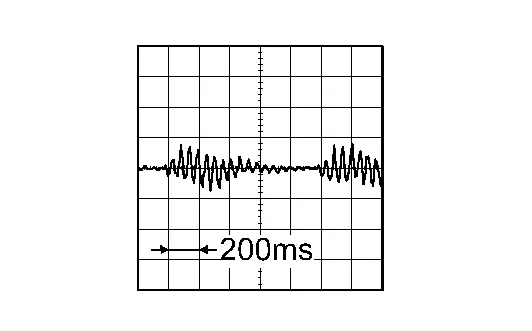
    LH M45 8 7
    RH 10 9

Is the inspection result normal?

YES>>

Replace VSP speaker. Refer to APPROACHING Nissan Ariya Vehicle SOUND FOR PEDESTRIANS (VSP) SPEAKER : Removal & Installation.

NO>>

Replace VSP control unit. Refer to APPROACHING Nissan Ariya Vehicle SOUND FOR PEDESTRIANS (VSP) CONTROL UNIT : Removal & Installation.

Approaching Vehicle Sound for Pedestrians (vsp) Speaker Nissan Ariya 2023

Component Inspection

CHECK VSP SPEAKER

  1. Power switch OFF.

  2. Disconnect VSP speaker connector.

  3. Check resistance between VSP speaker terminals.

VSP speakerResistance
ConnectorTerminals
LH B198 1 2 Approx. 4 Ω
RH E111

Is the inspection result normal?

YES>>

Inspection End.

NO >>

Replace VSP speaker. Refer to APPROACHING Nissan Ariya Vehicle SOUND FOR PEDESTRIANS (VSP) SPEAKER : Removal & Installation.