Component Parts/circuit Diagnosis
- Power Supply and Ground Circuit (cplc)
- Power Supply and Ground Circuit (dc/dc Converter)
- Power Supply and Ground Circuit (on-Board Charger)
- Charge Port
- Charge Port Circuit
- Dc/dc Converter Insulation Resistance Inspection
- High Voltage Junction Box Insulation Resistance Inspection
Power Supply and Ground Circuit (cplc) Nissan Ariya 2026
Diagnosis Procedure
PERFORM VCM DIAGNOSIS
 With CONSULT
Power switch ON.
Check “self-diagnostic result” in “EV/HEV” using CONSULT.
Is DTC detected?
YES>>Perform the trouble diagnosis for the detected DTC.
NO>>GO TO 2.
PERFORM ON-BOARD CHARGER DIAGNOSIS
With CONSULT
Power switch ON.
Check “self-diagnostic result” in “CHARGER/POWER DELIVERY MODULE” using CONSULT.
Is DTC detected?
YES>>Perform the trouble diagnosis for the detected DTC.
NO>>GO TO 3.
CHECK FUSE
Power switch OFF.
Check that the following fuse is not blowing.
Fuse No. Capacity #19 5A
Is the fuse blown (open)?
YES>>Replace the fuse after repairing the applicable circuit.
NO>>GO TO 4.
CHECK CPLC POWER SUPPLY
Remove CPLC harness connector.
Check the voltage between CPLC harness connector and ground.
+ − Voltage
(Approx.)CPLC Connector Terminal E35 1 Ground 12 V battery power supply
Is the inspection result normal?
YES>>GO TO 5.
NO>>GO TO 6.
CHECK CPLC POWER SUPPLY CIRCUIT
Remove FUSE BLOCK (J/B) harness connector.
Check the continuity between CPLC harness connector and FUSE BLOCK (J/B) harness connector.
CPLC FUSE BLOCK (J/B) Continuity Connector Terminal Connector Terminal E35 1 B112 35 Existed Also check harness for short to ground and to power.
Is the inspection result normal?
YES>>Check 12V battery power supply.
NO>>Repair or replace error-detected parts.
CHECK CPLC SIGNAL CIRCUIT-1
Remove charge port harness connector.
Check the continuity between CPLC harness connector and charge port harness connector.
CPLC CHARGE PORT Continuity Connector Terminal Connector Terminal E606 9 E28 4 Existed 10 3 Also check harness for short to ground and to power.
Is the inspection result normal?
YES>>GO TO 7.
NO>>Repair or replace error-detected parts.
CHECK CPLC SIGNAL CIRCUIT-2
Remove on-board charger harness connector.
Check the continuity between charge port harness connector and on-board charger harness connector.
CHARGE PORT ON-BOARD CHARGER Continuity Connector Terminal Connector Terminal E28 3 E30 7 Existed 4 8 Also check harness for short to ground and to power.
Is the inspection result normal?
YES>>INSPECTION END
NO>>Repair or replace error-detected parts.
Power Supply and Ground Circuit (dc/dc Converter) Nissan Ariya 2026
Diagnosis Procedure
CHECK FUSIBLE LINK
Check that the fusible link below is not blown.
| Fusible link number | Capacity |
|---|---|
| A | 450 A |
Is the fusible link blown?
YES>>Replace the fusible link after repairing the applicable circuit.
NO>>GO TO 2.
CHECK 12V BATTERY POWER SUPPLY
Power switch OFF.
Disconnect DC/DC converter connector.
Check voltage between DC/DC converter Nissan Ariya vehicle side harness connector and ground.
+ − Voltage DC/DC converter Connector Terminal H4 7 Ground 12V battery voltage
Is the inspection result normal?
YES>>INSPECTION END
NO>>GO TO 3.
CHECK DC/DC CONVERTER GROUND CIRCUIT
Check for continuation between the metal parts of the DC/DC converter  and ground.
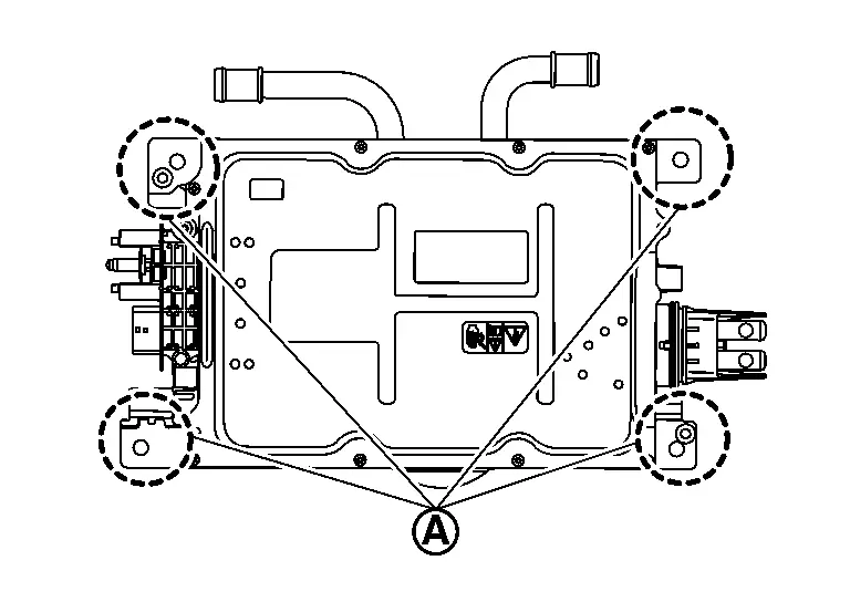
Is there continuation?
YES>>GO TO 4.
NO>>Repair or replace error-detected parts.
CHECK 12V BATTERY POWER SUPPLY CIRCUIT
Disconnect fuse block (J/B) connector.
Check for continuation between DC/DC converter Nissan Ariya vehicle side harness connector and battery terminal integrated fusible link vehicle side harness connector.
DC/DC converter Battery terminal with fusible link Continuity Connector Terminal Connector Terminal H4 7 H3 9 Existing
Is the inspection result normal?
YES>>Check 12V battery power supply circuit.
NO>>Repair or replace error-detected parts.
Power Supply and Ground Circuit (on-Board Charger) Nissan Ariya 2023
Diagnosis Procedure
CHECK FUSE
Check that the fuse below is not blown.
- 10 A
Is the fuse blown?
YES>>Replace the fuse after repairing the applicable circuit.
NO>>GO TO 2.
CHECK 12V BATTERY POWER SUPPLY
Disconnect On-board charger connector.
Check voltage between On-board charger Nissan Ariya vehicle side harness connector and ground.
+ − Voltage On-board charger Connector Terminal E30 1 Ground 12V battery voltage
Is the inspection result normal?
YES>>INSPECTION END
NO>>GO TO 3.
CHECK ON-BOARD CHARGER GROUND CIRCUIT
Power switch OFF.
Disconnect On-board charger harness connector.
Check for continuation between the On-board charger harness connector and ground.
+ − Continuity On-board charger Connector Terminal E30 6 Ground Existing 12
Is the inspection result normal?
YES>>Check 12V battery power supply circuit.
NO>>Repair or replace error-detected parts.
Charge Port Nissan Ariya first Gen
Component Inspection
CHECK CHARGE PORT CONDITION
Check damage, dust and foreign matter in charge port. Refer to CHARGE PORT : Periodic Maintenance Operation.
Is the inspection result normal?
YES>>GO TO 2.
NO>>Clean or replace charge port. Refer to CHARGE PORT : Removal & Installation.
CHECK CHARGE PORT-1
Disconnect charge port harness connector.
Check the continuity between charge port terminals and normal charge port side harness connector of same terminals.
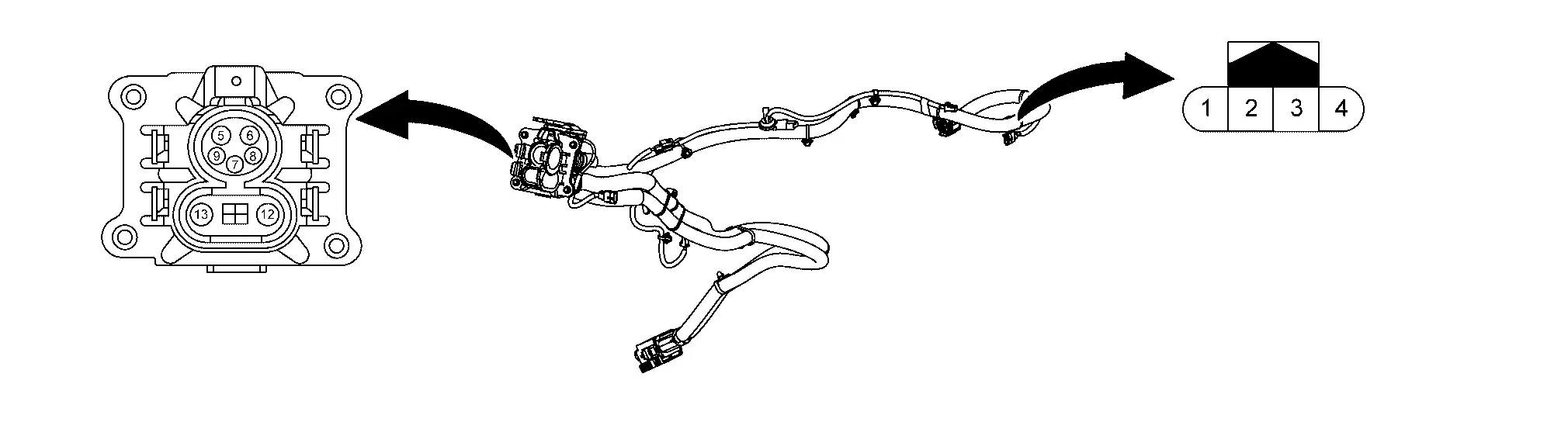
Charge port Charge port side harness connector Continuity Connector Terminal Connector Terminal H41 8 E28 2 Existed 9 1
Is the inspection result normal?
YES>>GO TO 3.
NO>>Replace charge port. Refer to CHARGE PORT : Removal & Installation.
CHECK CHARGE PORT-2
Check the resistance between charge port side harness connector and charge port ground.
| Charge port side harness connector | Charge port | Resistance (kΩ) | ||
|---|---|---|---|---|
| Connector | Terminal | Connector | Terminal | |
| E28 | 2 | H41 | 7 | 2.43 − 2.97 |
Is the inspection result normal?
YES>>GO TO 4.
NO>>Replace charge port. Refer to CHARGE PORT : Removal & Installation.
CHECK CHARGE PORT TEMPERATURE SENSOR
Check the resistance between charge port side harness connector terminals.
| Charge port | Resistance (kΩ) | |||
|---|---|---|---|---|
| Connector | Terminal | Connector | Terminal | |
| E27 | 20 | E27 | 18 | 4 - 170 |
| 19 | ||||
Is the inspection result normal?
YES>>INSPECTION END
NO>>Replace charge port. Refer to CHARGE PORT : Removal & Installation.
Insulation Resistance Check
CHECK INSULATION RESISTANCE OF CHARGE PORT (1)
Using insulation resistance tester, measure insulation resistance between charge port terminals.

Unlike normal resistance testers, insulation resistance testers (multi tester) are used by applying a voltage of 500 V. For this reason, improper handling of an insulation resistance tester may cause an electric shock. In addition to this, if an insulation resistance tester is used to the 12 V circuit, its electric devices may be damaged. To avoid these hazards, carefully read the handling manual of insulation resistance tester and perform safe operation.
| Charge port | Resistance | |
|---|---|---|
| + | - | |
| Terminal | ||
| 5 | 7 | 40 MΩ or more |
| 6 | ||
Is the inspection result normal?
YES>>INSPECTION END
NO>>GO TO 2.
CHECK INSULATION RESISTANCE OF CHARGE PORT (2)
Remove charge port from the Nissan Ariya vehicle.Refer to CHARGE PORT : Removal & Installation.
Using insulation resistance tester, measure insulation resistance between charge port terminals.
Unlike normal resistance testers, insulation resistance testers (multi tester) are used by applying a voltage of 500 V. For this reason, improper handling of an insulation resistance tester may cause an electric shock. In addition to this, if an insulation resistance tester is used to the 12 V circuit, its electric devices may be damaged. To avoid these hazards, carefully read the handling manual of insulation resistance tester and perform safe operation.
| Charge port | Resistance | |
|---|---|---|
| + | - | |
| Terminal | ||
| 5 | 7 | 40 MΩ or more |
| 6 | ||
Is the inspection result normal?
YES>>Replace On-board charger.Refer to ON-BOARD CHARGER : Disassembly & Assembly.
NO>>Replace charge port. Refer to CHARGE PORT : Removal & Installation.
Charge Port Circuit Nissan Ariya 1st generation
Diagnosis Procedure
CHECK CHARGE PORT
Turn power switch OFF.
Disconnect charge port harness connector.
Check the charge port. Component Inspection
Is the inspection result normal?
YES>>GO TO 2.
NO>>Replace charge port. Refer to CHARGE PORT : Removal & Installation.
CHECK EVSE CONNECTION DETECTING CIRCUIT POWER SUPPLY
Turn power switch ON.
Check the voltage between normal charge port harness connector and ground.
+ − Voltage Charge port Connector Terminal E28 2 Ground 5.0 V
Is the inspection result normal?
YES>>GO TO 4.
NO>>GO TO 3.
CHECK EVSE CONNECTION DETECTING CIRCUIT
Turn power switch OFF.
Disconnect on-board charger harness connector .
Check the continuity between charge port harness connector and on-board charger harness connector.
Charge port On-board charger Continuity Connector Terminal Connector Terminal E28 2 E30 4 Existed
Is the inspection result normal?
YES>>GO TO 6.
NO>>Repair or replace error-detected parts.
CHECK EVSE COMMUNICATION CIRCUIT
Check the continuity between charge port harness connector and on-board charger harness connector.
Charge port On-board charger Continuity Connector Terminal Connector Terminal E28 1 E30 9 Existed
Is the inspection result normal?
YES>>GO TO 5.
NO>>Repair or replace error-detected parts.
CHECK HIGH-VOLTAGE HARNESS
Remove charge port. Refer to CHARGE PORT : Removal & Installation.
Check the continuity between charge port harness connector and on-board charger harness connector.
Charge port On-board charger Continuity Connector Terminal Connector Terminal H41 5 H43 16 Existed 6 17
Is the inspection result normal?
YES>>GO TO 6.
NO>>Replace charge port. Refer to CHARGE PORT : Removal & Installation.
CHECK INTERMITTENT INCIDENT
Check the intermittent incident. Refer to Intermittent Incident.
Is the inspection result normal?
YES>>Replace On-board charger. Refer to ON-BOARD CHARGER : Disassembly & Assembly.
NO>>Repair or replace error-detected parts.
Dc/dc Converter Insulation Resistance Inspection Nissan Ariya SUV
Diagnosis Procedure
PRECONDITIONING
Disconnect the high voltage circuit. Refer to HOW TO DISCONNECT HIGH VOLTAGE : Precautions.
Check the voltage in the high voltage circuit.Refer to CHECK VOLTAGE IN HIGH VOLTAGE CIRCUIT : Precautions.
GO TO 2.
CHECK DC/DC CONVERTER INSULATION RESISTANCE
Remove the DC/DC converter from the high voltage junction box.
Check the insulation resistance between the DC/DC converter terminals and the metal parts of the DC/DC converter itself using an insulation resistance tester.
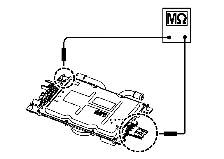
+ − Resistance DC/DC converter terminal part Terminal 8 Metal parts of the DC/DC converter itself More than 50MΩ 9
Is the inspection result normal?
YES>>INSPECTION END
NO>>Replace DC/DC converter. Refer to DC/DC CONVERTER : Disassembly & Assembly.
High Voltage Junction Box Insulation Resistance Inspection Nissan Ariya first Gen
Diagnosis Procedure
CHECK HIGH VOLTAGE JUNCTION BOX INSULATION RESISTANCE
Remove the On-board charger from the Nissan Ariya vehicle.Refer to HIGH VOLTAGE JUNCTION BOX : Disassembly & Assembly.
Check the insulation resistance between the high voltage junction box and the On-board charger body using an insulation resistance tester.
+ − Resistance High voltage junction box Connector Terminal PTC heater terminal H1 13 High voltage junction box body More than 50MΩ 14 Inverter (front) terminal H10 P N Electric compressor terminal H11 18 19 DC/DC converter terminal H13 36 37 On-board charger terminal H15 33 34 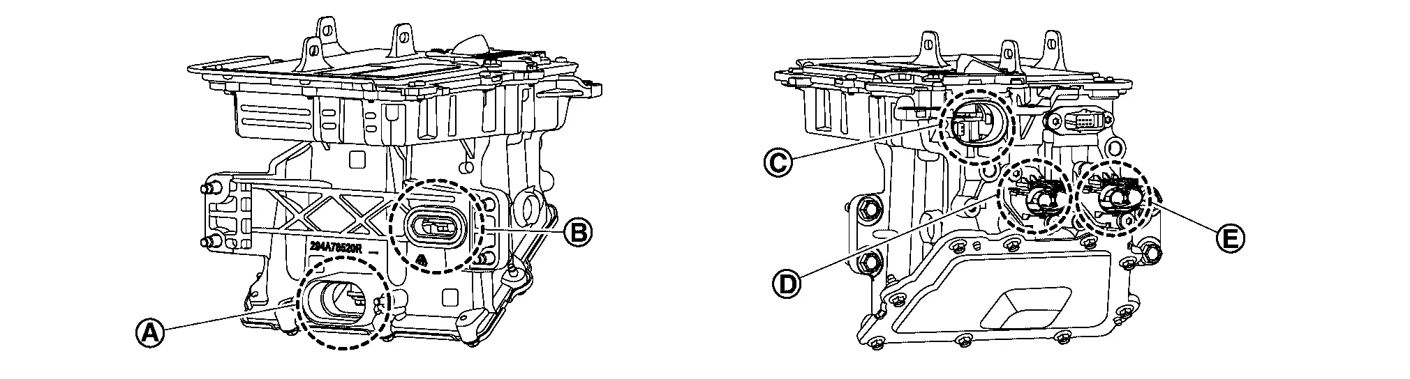
DC/DC converter terminal 
On-board charger terminal 
Inverter (front) terminal 
Electric compressor terminal 
PTC heater terminal
Is the inspection result normal?
YES>>INSPECTION END
NO>>Replace high voltage junction box. Refer to HIGH VOLTAGE JUNCTION BOX : Disassembly & Assembly.