Removal and Installation

In this manual: Removal and Installation
How to Use This Manual — 1Precautions — 1Preparation — 1Vehicle Information — 1Basic Inspection — 1Preparation. Commercial Service Tools Or/and Repair Part — 1Description — 1Component Parts — 1System — 1Diagnosis System (vcm) — 1Ecu Diagnosis Information. Vcm — 1Ev Control System — 1Ev/hev (vcm) — 1Component Parts /circuit Diagnosis — 1Ev Control System — 1Periodic Maintenance. Ev System Warning Lamp — 1Removal and Installation. Vcm — 1Traction Motor System :: Front Traction Motor — 1Preparation — 1Description — 4Basic Inspection — 2Dtc Diagnosis — 2Component Parts /circuit Diagnosis — 1Traction Motor System :: Rear Traction Motor — 1Description — 4Basic Inspection — 2Dtc Diagnosis — 2Component Parts /circuit Diagnosis — 1Removal and Installation — 1Ev Battery System :: 66kwh Li-Ion Battery — 1Description — 4Basic Inspection — 2Dtc Diagnosis — 2Component Parts /circuit Diagnosis — 1Removal and Installation — 1Disassembly and Assembly — 2Service Data — 1Ev Battery System :: 91kwh Li-Ion Battery — 1Description — 4Basic Inspection — 2Dtc Diagnosis — 2Component Parts /circuit Diagnosis — 1Removal and Installation — 1Disassembly and Assembly — 1Service Data — 2Preparation. Vehicle Charging System — 1Vehicle Charging System :: Description — 1Component Parts — 2System — 1Diagnosis System (on-Board Charger) — 1Diagnosis System (dc/dc Converter) — 1Ecu Diagnosis Information — 1Vehicle Charging System — 1Charger/pd Module (on-Board Charger) — 1Cplc (cplc) — 1Dcdc (dc/dc Converter) — 1Component Parts/circuit Diagnosis — 1Symptom Diagnosis — 1Evse Inspection — 1Periodic Maintenance — 1Removal and Installation — 1Disassembly and Assembly — 1Preparation. High Voltage Cooling System — 1Description — 1Symptom Diagnosis. Overheating Cause Analysis — 1Periodic Maintenance — 1Coolant — 1Removal and Installation — 1Radiator — 1Service Data — 1Removal and Installation. Accelerator Control System — 1Reduction Gear: Re1f62a — 1Removal and Installation — 1Transaxle & Transmission :: Electric Shift — 1Description — 3Basic Inspection — 2Dtc Diagnosis — 2Component Parts /circuit Diagnosis — 1Removal and Installation — 1Rear Final Drive: Rn1r62a — 1Removal and Installation — 1Preparation. Front Axle System — 1Symptom Diagnosis. Noise, Vibration and Harshness (nvh) Troubleshooting — 1Periodic Maintenance — 1Removal and Installation — 1Service Data. Front Drive Shaft — 12wd — 14wd — 1Periodic Maintenance — 1Removal and Installation — 1Preparation. Front Suspension System — 1Symptom Diagnosis. Noise, Vibration and Harshness (nvh) Troubleshooting — 1Periodic Maintenance — 1Removal and Installation — 1Service Data — 1Symptom Diagnosis. Noise, Vibration and Harshness (nvh) Troubleshooting — 1Periodic Maintenance — 1Removal and Installation — 1Service Data — 1Preparation. Road Wheels & Tires System — 1Description — 1System — 1Ecu Diagnosis Information. Bcm (body Control Module) — 1Tpms — 1Dtc/circuit Diagnosis — 1Symptom Diagnosis — 1Periodic Maintenance. Road Wheels & Tires — 1Removal and Installation — 1Service Data — 1Preparation. Brake System — 1System Description — 1Component Parts — 1Ecu Diagnosis Information. Electrically-Driven Intelligent Brake Unit — 1Basic Inspection — 1Dtc/circuit Diagnosis — 1Symptom Diagnosis — 1Periodic Maintenance — 1Removal and Installation — 1Service Data — 1Preparation. Parking Brake System — 1System Description — 1Component Parts — 1System — 1Ecu Diagnosis Information. Abs Actuator and Electric Unit (control Unit) — 1Basic Inspection. Diagnosis and Repair Work Flow — 1Component Parts /circuit Diagnosis — 1Symptom Diagnosis — 1Removal and Installation — 1Brake Control System :: With Vdc — 1System Description — 3Basic Inspection — 2Dtc/circuit Diagnosis — 1Symptom Diagnosis — 2Removal and Installation — 1Brake Control System :: Automatic Brake Hold — 1System Description — 3Component Parts /circuit Diagnosis — 1Removal and Installation — 1Brake Control System :: E-Step — 1System Description — 3Removal and Installation — 1System Description — 1Ecu Diagnosis Information — 1Basic Inspection — 1Symptom Diagnosis — 1Rear Automatic Braking — 1System Description — 1Basic Inspection — 1Preparation. Steering System — 1System Description — 1Component Parts — 1Basic Inspection — 1Dtc/circuit Diagnosis — 1Symptom Diagnosis — 1Periodic Maintenance. Steering Wheel — 1Removal and Installation — 1Service Data — 1System Description — 1Component Parts — 1Steering Control System — 1Ecu Diagnosis Information. Power Steering Control Module — 1Dtc/circuit Diagnosis — 1Component Parts /circuit Diagnosis — 1Symptom Diagnosis — 1Removal and Installation. Power Steering Control Module — 1System Description — 1Removal and Installation — 1System Description — 1System — 1Basic Inspection. Diagnosis and Repair Work Flow — 1Dtc/circuit Diagnosis — 1Symptom Diagnosis — 1Component Parts — 1Basic Inspection — 1Removal and Installation — 1System Description — 1System — 1Ecu Diagnosis Information. Air Bag Diagnosis Sensor Unit — 1Basic Inspection — 1Dtc/circuit Diagnosis — 1Symptom Diagnosis — 1System Description. Description. Ventilation System — 1Removal and Installation — 1Preparation. Preparation — 1System Description — 1Basic Inspection — 1Symptom Diagnosis — 1Removal and Installation — 1Electric Compressor — 1Cooler Pipe and Hose — 1A/c Unit Assembly Cover — 1A/c Unit Assembly — 1Heater & Air Conditioning Control System :: Automatic Air Conditioning — 1System Description — 1Ecu Diagnosis Information — 1Basic Inspection — 2Dtc Diagnosis — 1Symptom Diagnosis — 1Removal and Installation — 2Preparation. Preparation — 1Symptom Diagnosis. Squeak and Rattle Trouble Diagnoses — 1Removal and Installation — 1Preparation. Instrument Panel — 1Component Parts — 1System — 1Ecu Diagnosis Information. Flexible Center Storage Control Module — 1Basic Inspection. Diagnosis and Repair Work Flow — 1Dtc/circuit Diagnosis — 1Symptom Diagnosis — 1Removal and Installation — 1Preparation. Preparation — 1Component Parts — 1System — 1Ecu Diagnosis Information. Driver Lumbar Support Control Module — 1Basic Inspection. Diagnosis and Repair Work Flow — 1Dtc/circuit Diagnosis — 1Symptom Diagnosis — 1Removal and Installation — 1System Description — 1System — 1Ecu Diagnosis Information — 1Basic Inspection — 1Dtc/circuit Diagnosis — 1Symptom Diagnosis — 1Manual Function Does Not Operate — 1Memory Function Does Not Operate — 1Removal and Installation — 1Preparation. Preparation — 1System Description — 1System (intelligent Key System) — 1Diagnosis System (bcm) — 1Ecu Diagnosis Information — 1Basic Inspection — 1Dtc/circuit Diagnosis — 1U2141-87 Can Comm Circuit — 1Power Supply and Ground Circuit — 1Symptom Diagnosis — 1Automatic Back Door Operation Does Not Operate — 1Back Door Does Not Open — 1Door Does Not Lock/unlock with Door Lock and Unlock Switch — 1Removal and Installation — 1Hood — 1Radiator Core Support — 1Charge Port Lid — 1Front Fender — 1Front Door — 1Rear Door — 1Back Door — 1Hood Lock — 1Front Door Lock — 1Rear Door Lock — 1Back Door Lock — 1Outside Key Antenna — 1System Description — 1System — 1Ecu Diagnosis Information. Inverter (front), Inverter (rear), Bcm, Intelligent Key Unit — 1Basic Inspection — 1Dtc/circuit Diagnosis — 1Symptom Diagnosis — 1Preparation — 1Symptom Diagnosis. Squeak and Rattle Trouble Diagnoses — 1Removal and Installation — 1System Description — 1Ecu Diagnosis Information — 1Basic Inspection — 1Dtc/circuit Diagnosis — 1Power Supply and Ground Circuit — 1Symptom Diagnosis — 1Front Passenger Side Power Window Does Not Operate — 1Rear Lh Side Power Window Does Not Operate — 1Rear Rh Side Power Window Does Not Operate — 1Removal and Installation. Power Window Main Switch — 1Preparation. Preparation — 1System Description — 1Ecu Diagnosis Information — 1Basic Inspection — 1Dtc/circuit Diagnosis — 1Power Supply and Ground Circuit — 1Sunroof Switch Assembly — 1Symptom Diagnosis — 1Auto Operation Does Not Operate — 1Removal and Installation — 1Preparation — 1Description — 1Symptom Diagnosis. Squeak and Rattle Trouble Diagnoses — 1Removal and Installation — 1Service Information — 6Repair Information — 1Precaution — 1Preparation — 1Removal and Installation — 1Service Data — 1Preparation. Preparation — 1Component Parts — 1System — 1Ecu Diagnosis Information — 1Wiring Diagram. Door Mirror — 1Basic Inspection. Diagnosis and Repair Work Flow — 1Dtc/circuit Diagnosis — 1Power Supply and Ground Circuit — 1Symptom Diagnosis — 1Removal and Installation — 1Exterior Lighting System :: Led Headlamp — 1System Description — 3Basic Inspection — 1Dtc/circuit Diagnosis — 1Symptom Diagnosis — 1Periodic Maintenance — 1Removal and Installation — 1System Description — 1System — 1Diagnosis System (bcm) — 1Ecu Diagnosis Information. Bcm, Intelligent Key Unit — 1Basic Inspection. Diagnosis and Repair Work Flow — 1Dtc/circuit Diagnosis — 1Symptom Diagnosis. Interior Lighting System Symptom — 1Removal and Installation — 1Service Data. Bulb Specifications — 1System Description — 1System — 1Ecu Diagnosis Information. Bcm, Ipdm E/r — 1Basic Inspection. Diagnosis and Repair Work Flow — 1Dtc/circuit Diagnosis — 1Symptom Diagnosis — 1Removal and Installation — 1System Description — 1Ecu Diagnosis Information. Bcm — 1Basic Inspection. Diagnosis and Repair Work Flow — 1Dtc/circuit Diagnosis — 1Symptom Diagnosis — 1Removal and Installation — 1Preparation. Preparation — 1Removal and Installation. Horn — 1Preparation. Commercial Service Tools Or/and Repair Part — 1System Description — 1Component Parts — 1Ecu Diagnosis Information. Approaching Vehicle Sound for Pedestrians (vsp) Control Unit — 1Approaching Vehicle Sound for Pedestrians (vsp) — 1Vsp [approaching Vehicle Sound for Pedestrians (vsp) Control Unit] — 1Approaching Vehicle Sound for Pedestrians (vsp) System — 1Removal and Installation — 1Removal and Installation — 1Wireless Charger — 1System Description — 1Basic Inspection — 1Dtc/circuit Diagnosis — 1Removal and Installation — 1Component Parts — 1System — 1Diagnosis System (bcm) — 1Ecu Diagnosis Information. Bcm — 1Basic Inspection — 1Dtc/circuit Diagnosis — 1Symptom Diagnosis — 1Removal and Installation — 1Can Fundamental — 1Description — 1Trouble Diagnosis — 1Can (controller Area Network) — 1Description — 1
11steps
~66min
5/5difficulty
Done 0 of 11
  • Rear Final Drive Side Oil Seal
  • Rear Final Drive Shaft Oil Seal
  • Rear Final Drive Air Breather
  • Rear Final Drive Assembly

Rear Final Drive Side Oil Seal Nissan Ariya 1st generation

REAR FINAL DRIVE SIDE OIL SEAL : Exploded View
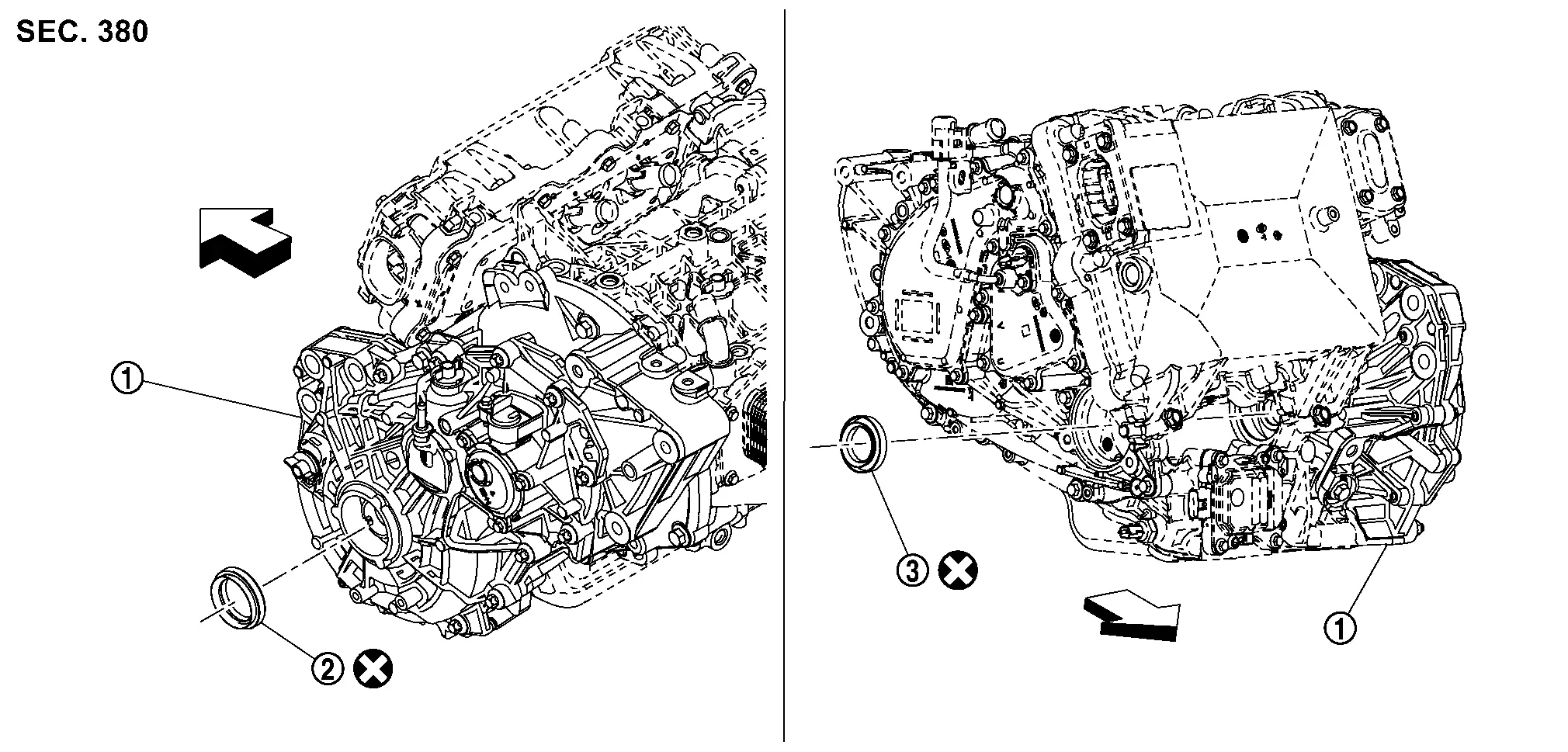
Rear final drive assembly Side oil seal (left side) Side oil seal (right side)
: Nissan Ariya Vehicle front
: Always replace after every disassembly.

REAR FINAL DRIVE SIDE OIL SEAL : Removal & Installation

REMOVAL

Remove the rear drive shaft. Refer to Removal and Installation.

  • When removing side oil seal (right side), remove link shaft assembly.

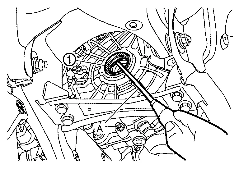
Remove side oil seal (left side and/or right side), using oil seal remover (A) (commercial service tool).
INSTALLATION

Note the following, and install in the reverse order of removal.

  • Using the drift (commercial service tool), drive the side oil seal within the dimension (C) and (D) shown as follows.
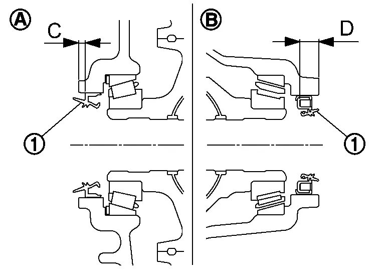
    : Left side
    : Right side
    Dimension (C) : 3.5 ±0.3 mm (0.138 ±0.012 in)
    Dimension (D) : 10 ±0.3 mm (0.39 ±0.012 in)

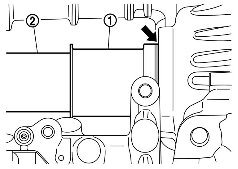
  • When link shaft is removed, install guide of link shaft according to the following procedure.

  1. Apply gear oil to the part of the guide where the seal lip of side oil seal contacts.

  2. Attach the guide onto side oil seal (right side) to prevent damage to the side oil seal (right side) of rear final drive.

  3. While holding the guide , securely insert link shaft to rear final drive and tighten the mounting bolts of link shaft bearing bracket to the specified torque. Refer to Exploded View.
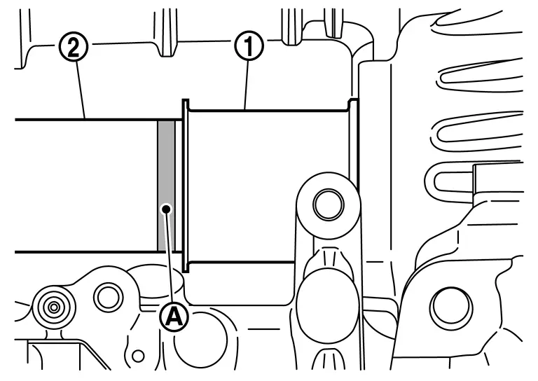
  4. Slide guide to groove on link shaft , and check that mark () of guide is appeared.

  • Check the oil level and the oil leakage after installation. And check the oil leakage from rear final drive assembly again, after driving the Nissan Ariya vehicle. Refer to Inspection.

Rear Final Drive Shaft Oil Seal Nissan Ariya 2026

REAR FINAL DRIVE SHAFT OIL SEAL : Exploded View
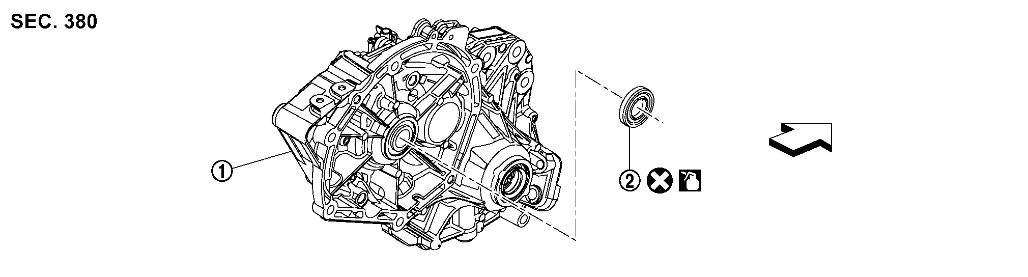
Rear final drive assembly Shaft oil seal
: Nissan Ariya Vehicle front
: Always replace after every disassembly.
: Apply gear oil.

REAR FINAL DRIVE SHAFT OIL SEAL : Removal & Installation

REMOVAL

Remove rear final drive assembly. Refer to REAR FINAL DRIVE ASSEMBLY : Unit Removal & Installation.

Remove shaft oil seal, using oil seal remover (commercial service tool).

INSTALLATION

Note the following, and install in the reverse order of removal.

  • Using a drift (commercial service tools), drive the shaft oil seal within the dimension (A) shown as follows.

    Dimension (A) : 2.0 ±0.3 mm (0.079 ±0.012 in)

  • Check the oil level and the oil leakage after installation. And check the oil leakage from rear final drive assembly again, after driving the Nissan Ariya vehicle. Refer to Inspection.

Rear Final Drive Air Breather Nissan Ariya first Gen

REAR FINAL DRIVE AIR BREATHER : Exploded View
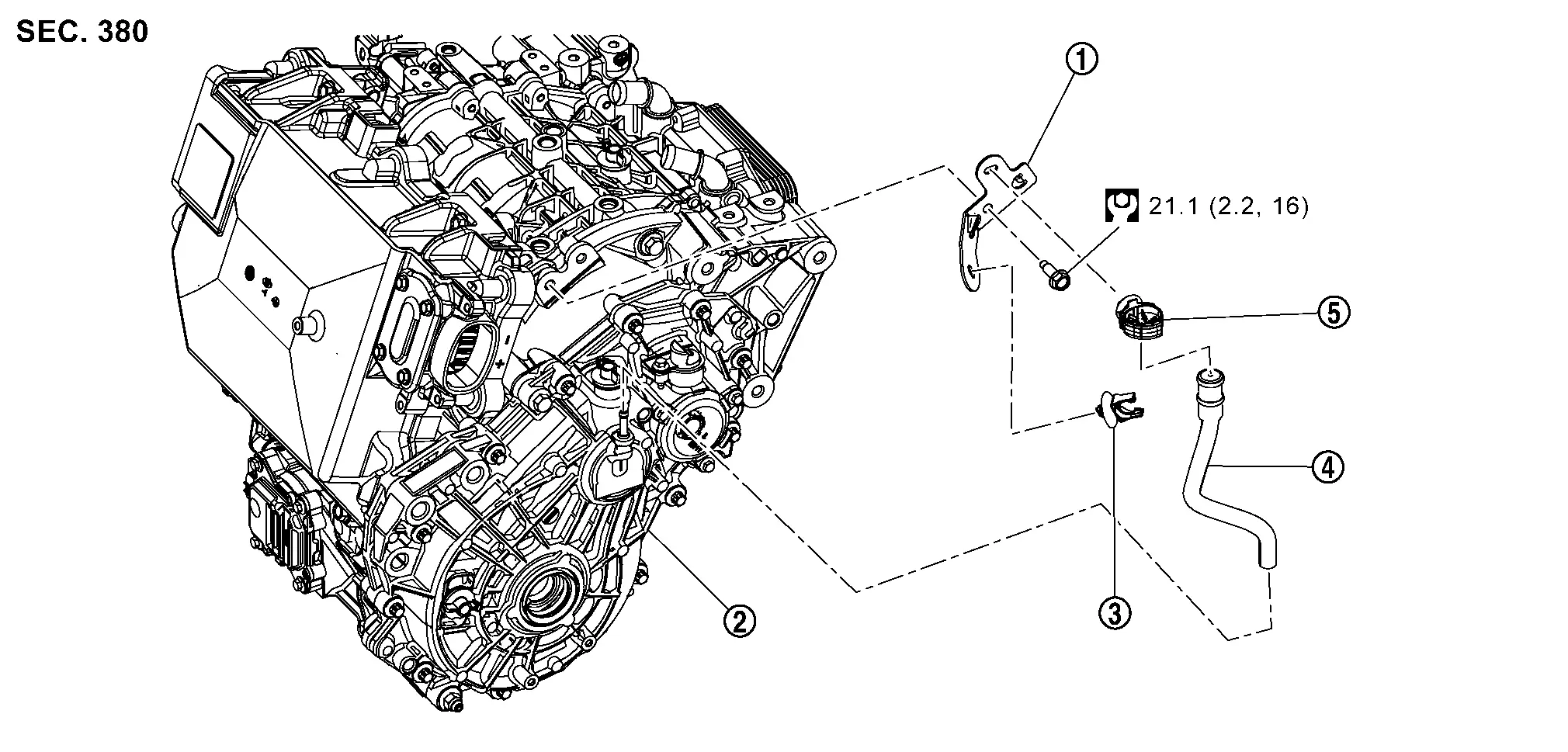
Bracket Rear final drive assembly Clip
Air breather hose Clip
: N·m (kg-m, ft-lb)

REAR FINAL DRIVE AIR BREATHER : Removal & Installation

REMOVAL

Remove rear diffuser. Refer to Removal & Installation.

Remove tire. Refer to ROAD WHEEL TIRE : Removal & Installation.

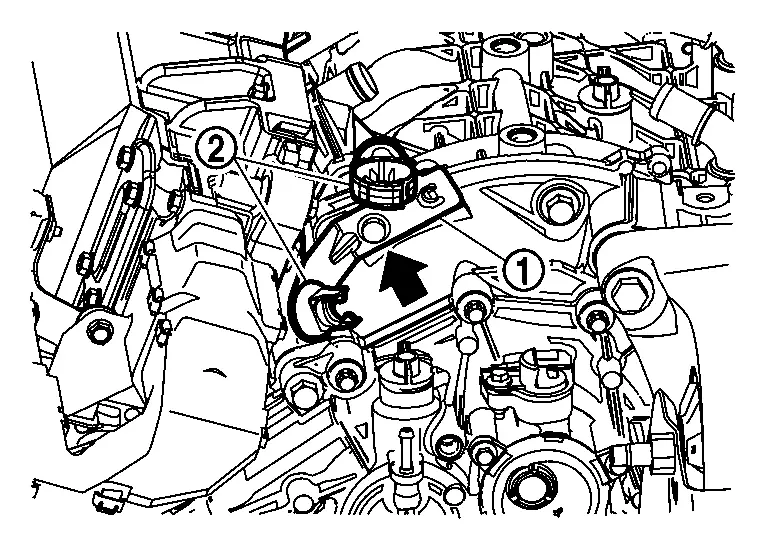
Remove air breather hose after removing it from clips .

Remove bracket and clips .
INSTALLATION

Note the following, and install in the reverse order of removal.

  • When installing air breather hose, preventing crush and clogging caused by bending.

  • Insert the air breather hose all the way to the bulged part of tube.

Rear Final Drive Assembly Nissan Ariya 2026

REAR FINAL DRIVE ASSEMBLY : Exploded View
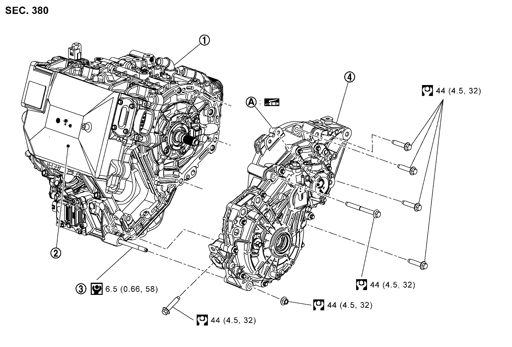
Rear traction motor Inverter (rear) Stud bolt
Rear final drive assembly
Inside of input shaft (insertion part of rear traction motor shaft splines)
: N·m (kg-m, in-lb)
: N·m (kg-m, ft-lb)
: Apply lithium-based grease including molybdenum disulphide.

REAR FINAL DRIVE ASSEMBLY : Unit Removal & Installation

REMOVAL

Drain the gear oil. Refer to Draining.

Remove rear suspension member assembly together with rear final drive assembly and rear traction motor with inverter (rear) from Nissan Ariya vehicle. Refer to REAR SUSPENSION MEMBER : Removal & Installation.

Remove rear final drive assembly, rear traction motor and inverter (rear) as a set from rear suspension member assembly. Refer to Removal and Installation.

Remove rear final drive air breather hose. Refer to REAR FINAL DRIVE AIR BREATHER : Removal & Installation.

Remove rear motor mounting insulator assembly (front side) and rear motor mounting insulator assembly (left side) . Refer to Removal and Installation.

Remove the bolts and a nut that fasten rear final drive assembly and rear traction motor.
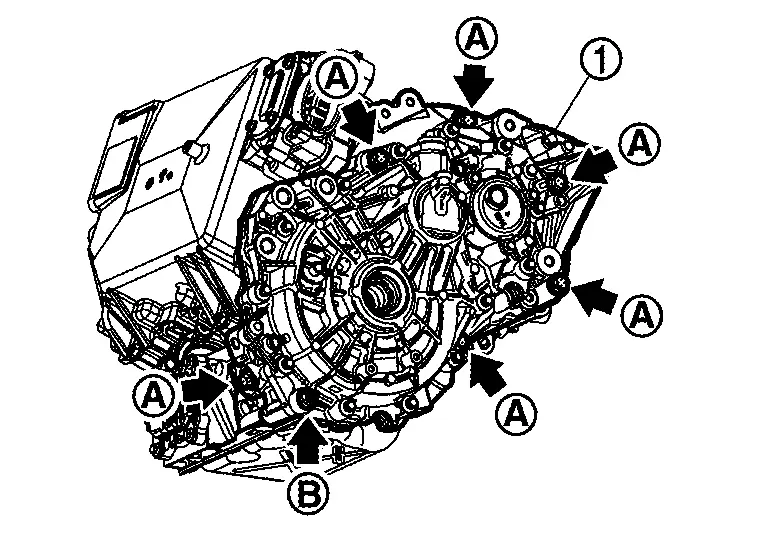
Remove rear final drive assembly from rear traction motor.
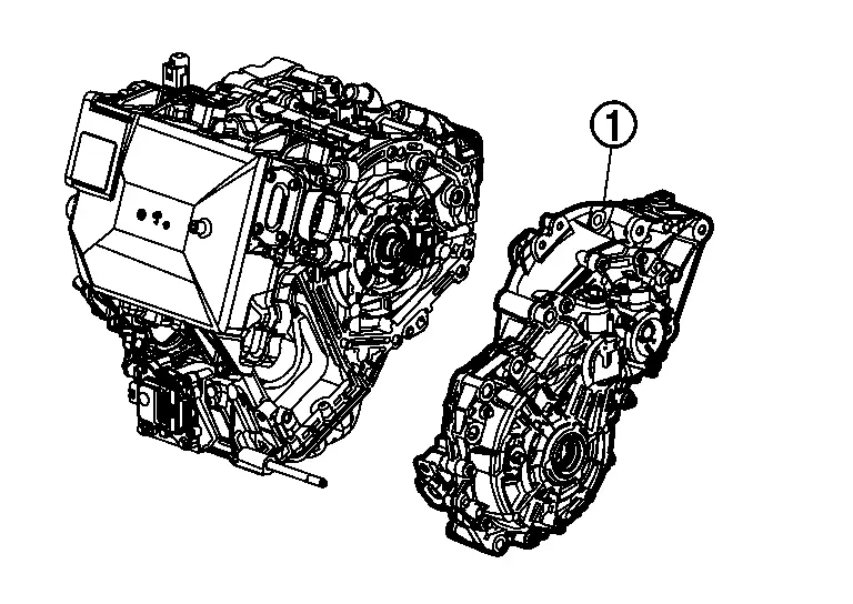
INSTALLATION

Note the following, and install in the reverse order of removal.

  • For each tightening torque, refer to REAR FINAL DRIVE ASSEMBLY : Exploded View.

  • Check fitting of dowel pins on rear traction motor side of rear final drive installation surface, and remove any moisture, oil, or foreign material from matching surface on rear traction motor and rear final drive.

  • Before installing rear final drive assembly to rear traction motor, apply recommended grease to the inside of rear final drive input shaft (insertion part of rear traction motor shaft splines), as per the following procedure.

    • For applying grease, refer to REAR FINAL DRIVE ASSEMBLY : Exploded View.

  1. Clean rear traction motor shaft splines and inside of rear final drive input shaft ​to remove old grease and powder arisen from abrasion.

  2. Inject the specified amount of recommended grease into the rear final drive input shaft back side (greasing part: ).
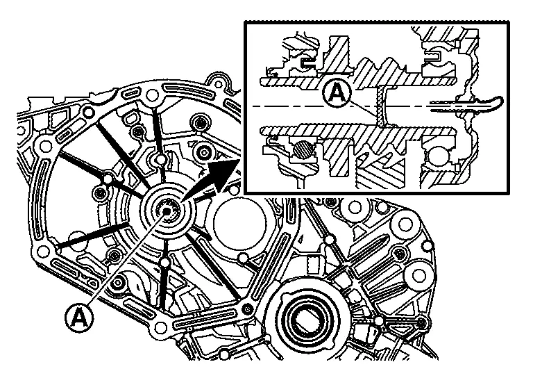
    Specified grease amount : 3.5 ±0.5 g (0.12 ±0.018 oz)

  • When removing rear final drive assembly from rear traction motor, replace O-ring of rear traction motor shaft. Refer to Exploded View.

  • When installing rear final drive assembly to rear traction motor , align markings on rear final drive input shaft and rear traction motor shaft.
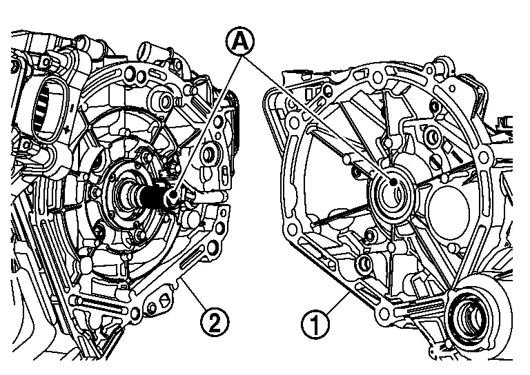
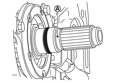
  • When installing link shaft, install guide of link shaft according to the following procedure.

  1. Replace side oil seal (right side) of rear final drive. Refer to REAR FINAL DRIVE SIDE OIL SEAL : Removal & Installation.

  2. Apply gear oil to the part of the guide where the seal lip of side oil seal contacts.

  3. Attach the guide onto side oil seal (right side) to prevent damage to the side oil seal (right side) of rear final drive.

  4. While holding the guide , securely insert link shaft to rear final drive and tighten the mounting bolts of link shaft bearing bracket to the specified torque. Refer to Exploded View.

  5. Slide guide to groove on link shaft , and check that mark () of guide is appeared.

  • Check the oil level and the oil leakage after installation. Refer to Inspection.