Vehicle Charging System
- Diagnosis and Repair Work Flow
- Additional Service When Replacing Cplc
Diagnosis and Repair Work Flow Nissan Ariya: FE0
Work Flow
OVERALL SEQUENCE
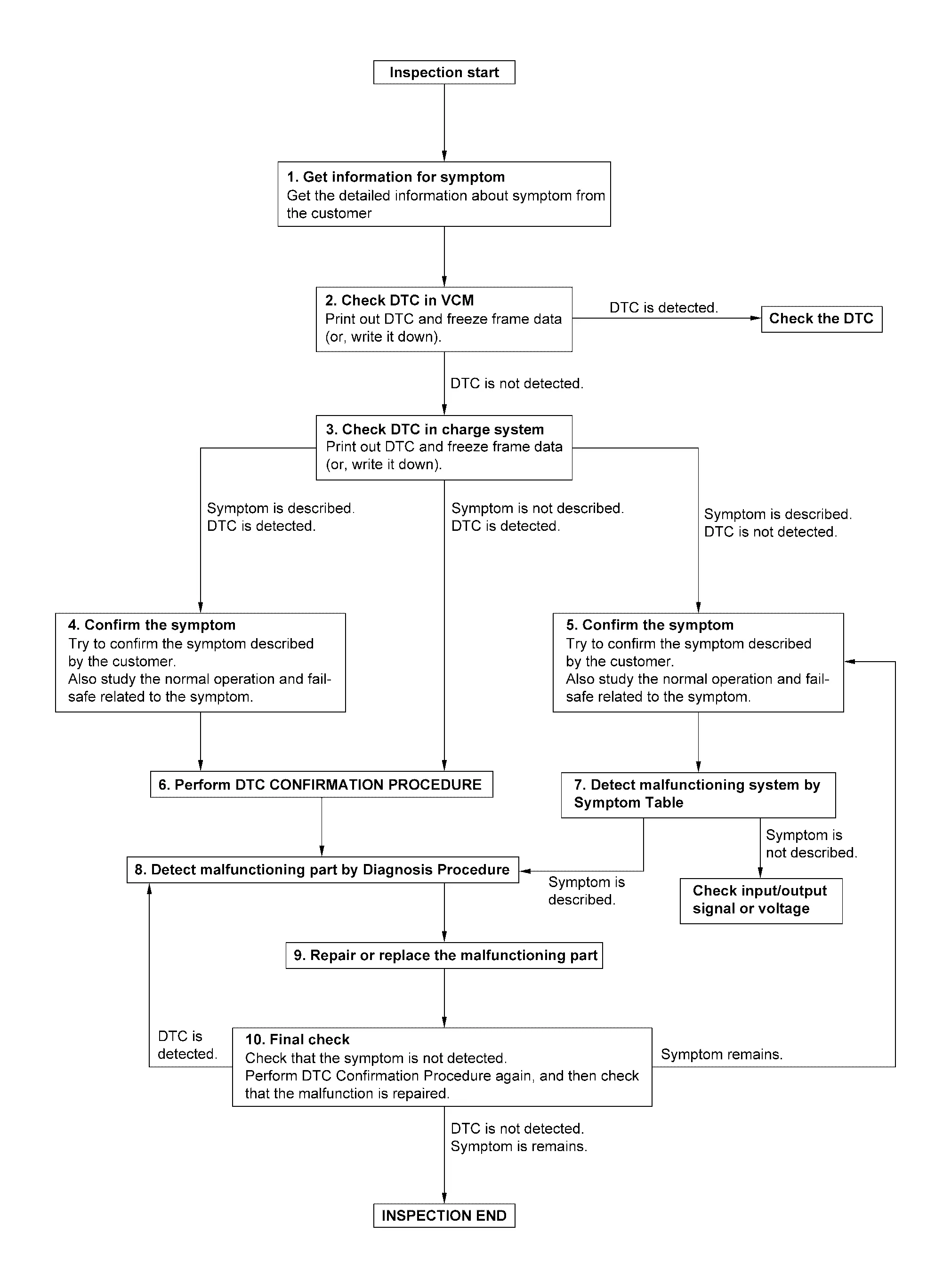
DETAILED FLOW
GET INFORMATION FOR SYMPTOM
Get the detailed information from the customer about the symptom (the condition and the environment when the incident/malfunction occurred) using the “Diagnostic Work Sheet”.
If there is a problem with the Nissan Ariya vehicle, use "Diagnostic Work Sheet A".
Use "Diagnostic Work Sheet B" for problems related to charging, such as "cannot charge", "charging stops halfway", or "warning lamp turns on after charging".
Refer to Diagnostic Work Sheet.
>>GO TO 2.
CHECK DTC IN VCM
Check DTC in VCM.
Are any DTCs detected?
YES>>Check detected DTC. Refer to DTC Index.
NO>>GO TO 3.
CHECK DTC IN Nissan Ariya Vehicle CHARGE SYSTEM
Check DTC in vehicle charge system.
VCM:Refer to DTC Index.
On-board charger: Refer to DTC Index.
DC/DC converter: Refer to DTC Index.
CPLC: Refer to DTC Index.
When DTC is detected, perform the following procedure.
Write DTC and freeze frame data.
Erase DTC
Investigate the relationship between the cause specified by DTC and the information of symptom from the customer. (It is effective to utilize the Symptom Table.) Refer to Symptom Table.)
Are there any symptoms described and any DTC is detected?
Symptom is described, DTC is detected>>GO TO 4.
Symptom is described, DTC is not detected>>GO TO 5.
Symptom is not described, DTC is detected>>GO TO 6.
CONFIRM THE SYMPTOM
Try to confirm the symptom described by the customer.
Investigate the relationship between the cause specified by DTC and the information of symptom from the customer. (It is effective to utilize the Symptom Table. Refer to Symptom Table.)
Verify relation between the symptom and the condition when the symptom is occurred.
>>GO TO 6.
CONFIRM THE SYMPTOM
Try to confirm the symptom described by the customer.
Also study whether it is the normal operation or fail-safe related to symptom.
Fail-safe: Refer to Fail-safe.
Normal operation: Refer to Symptom Description.
Diagnosis Work Sheet is useful to verify the incident.
Verify relation between the symptom and the condition when the symptom is detected.
>>GO TO 7.
PERFORM DTC CONFIRMATION PROCEDURE
Perform DTC CONFIRMATION PROCEDURE for the displayed DTC, and then check that DTC is detected again.
Is DTC detected?
YES>>GO TO 8.
NO>>Check according to the symptom cause simulation test. Refer to Intermittent Incident.
DETECT MALFUNCTIONING SYSTEM BY SYMPTOM TABLE
Detect malfunctioning system according to symptom index based on confirmation of symptom in step 4, and determine the trouble diagnosis order based on possible causes and symptoms.Refer to Symptom Table.
Is the malfunction system detected?
YES>>GO TO 9.
NO>>Monitor output data from related sensors or check voltage of related terminals using CONSULT. Refer to input output specified value of corresponded parts.
DETECT MALFUNCTIONING PART BY DIAGNOSIS PROCEDURE
Inspect according to Diagnosis Procedure of the system.
Is a malfunctioning part detected?
YES>>GO TO 9.
NO>>Check according to the symptom cause simulation test. Refer to Intermittent Incident.
REPAIR OR REPLACE MALFUNCTIONING PART
Repair or replace the identified malfunctioning part.
Reconnect parts or connectors disconnected during Diagnosis Procedure again after repair and replacement.
Check DTC. If DTC is displayed, erase it.
GO TO 10.
FINAL CHECK
When DTC was detected in step 3, perform DTC CONFIRMATION PROCEDURE or Component Function Check again, and then check that the malfunction is completely repaired.
When symptom was described from the customer, refer to confirmed symptom in step 3 or 4, and check that the symptom is not detected.
Is DTC detected and does symptom remain?
YES-1(DTC is detected)>>GO TO 8.
YES-2(Symptom remains)>>GO TO 5.
NO>>Before returning the Nissan Ariya vehicle to the customer, always erase all DTCs.
Diagnostic Work Sheet
DESCRIPTION
There are many operating conditions that lead to the malfunction of “charging system” components. If such conditions are understood. trouble shooting can be faster and more accurate.
| Key points of interview | |
|---|---|
| What | Nissan Ariya Vehicle and parts |
| When | Date, Frequencies |
| Where | Road conditions |
| How | Operating conditions, Weather conditions |
| What happened | Symptom |
In general, the way customers explanation of symptom differs from person to person, so it is important to fully understand the symptom and condition by conducting sufficient interviews.
Use "Diagnostic Work Sheet" to systematize all the information for troubleshooting.
If there is a problem with the vehicle, use "Diagnostic Work Sheet A".
Use "Diagnostic Work Sheet B" for problems related to charging, such as "cannot charge", "charging stops halfway", or "warning lamp turns on after charging".
DIAGNOSTIC WORKSHEET A
| Diagnostic Work Sheet A | |||||
| Customer name | License plate No. | Date of first registration | |||
| Model | |||||
| Repair order issue date | VIN | Mileage | km or mile | ||
| Question | Group | Information from the customer | |
|---|---|---|---|
| Nissan Ariya Vehicle condition at malfunction occurred | R/Q/N/O | □READY® □Quick charge(Q) □Normal charge(N) □Others(O) | |
| Symptom | R | □"READY" not enable □Poor drivability □Shock □Vibration □Driving impossible □Fixed shift position □Poor shift □Poor braking □Poor acceleration □Poor electricity consumption □switch malfunction □Warning lamp ON □Others ( ) |
|
| Details of symptom | |||
| Information display indication | |||
| Electricity consumption | km(mile)/kw | ||
| Li-ion battery charge level | / | ||
| Q/N | □Charging unable □Charging discontinued □Slow charging □Poor timer charging □Poor remote charging □Immediate charging unable □Others ( ) |
||
| Details of symptom | |||
| Quick charger monitor indication | |||
| O | □A/C inoperative □Poor A/C □Dead 12 V battery □Others ( ) |
||
| Details of symptom | |||
| Location/status of occurrence | R/O | □Not applicable □ordinary road □Highway □Mountain pass □Rough road □Level road □Uphill □ Downhill □Left/right turn □Others ( ) |
|
| Q/N/O | □Start of charge □During charge □After stop charging □During standby of timer charging □During timer charging □At the end of timer charging □During remote charging □Others ( ) |
||
| Driving condition | R | □ At the system startup □ During READY (Nissan Ariya Vehicle stopped) □ At start □ During acceleration □ During driving with a constant speed □ During coasting □ During braking □ Right before stopping □ Right after stopping □ During POWER OFF operation □ A/C ON □ During shift change □ Others ( ) |
|
| Nissan Ariya Vehicle speed | km/h (MPH) | ||
| Accelerator pedal opening angle | / 8 | ||
| Quick charge | Q | Quick charger maker | □ Not applicable □ Applicable ( ) |
| Location | |||
| Model maker | |||
| Serial No. | |||
| Setting | |||
| Others | |||
| EVSE | N | Manufacturer | □ Genuine □ Others ( ) |
| Wall outlet | N | □Not applicable □ Applicable | |
| Location | |||
| Voltage | V | ||
| Breaker | A | ||
| Other information | |||
| Li-ion battery remaining energy | Q/N/O | □ Not applicable □ Applicable ( ) |
|
| Shift position/operation | R | □ P □ R □ N □ D □ ECO □ When operating ( ⇒ ) | |
| Weather condition | R/Q/N/O | □ Not applicable □ Applicable | |
| Weather | |||
| Temperature | °C | ||
| Occurrence frequency | □ All the time □ Once □ Sometimes ( times in the past) □ Others ( ) |
||
| Timing of recovery from malfunction | □ POWER OFF □ Removal of 12V battery terminal □Shift lever operation □ During driving □ READY □ Others ( ) |
||
【REMARKS 】 |
|||
DIAGNOSTIC WORKSHEET B (RELATED THE CHARGING)
Pointed out concerns from the customer. Select from below (Multiple choices available).
| 1) What are the symptoms? | 2) What timing does concern occur? | 3) initial confirmation | 4) Nissan Ariya Vehicle settings | |
| Normal charge | □ Normal charge will not start (Unable to start) □ Normal charge stops during charging □ After normal charge □ During normal charge □ Unable to disconnect the charge connector from the normal charge port □ Breaker of the infrastructure trips □ Others |
□ A : Normal Charge Use Normal charging station with cable |
1) How often did this concern occurs? □Always □Sometimes □Once |
1) Has the timer been used for charging? □Yes □No □Don't know 2) Has remote control been used for charging? □Yes □No □Don't know 3) Has immediate charge conducted by turning ON the immediate charge SW? □Yes □No □Don't know 4) Has Charging Device been connected correctly? □Yes □No □Don't know 5) When starting the charge, was the power SW on the Nissan Ariya vehicle OFF? □Yes □No □Don't know 6) Was Li-ion battery fully charged when concern occurred? □Yes □No □Don't know |
2) Did Charging Device display any failure messages? □Yes □No □Don't know |
||||
3) Please list a model and maker of Charging Device. □___________________________ □Don't know |
||||
4) Does same concern occur with different Charging Device? □Yes □No □Don't know/ Different charging Device not used |
||||
□ B : Normal Charge Use NISSAN Mode3 cable and normal charging station with EV socket-outlet |
1) How often did this concern occurs? □Always □Sometimes □Once |
|||
2) Did Charging Device display any failure messages? □Yes □No □Don't know |
||||
3) Please list a model and maker of Charging Device. □___________________________ □Don't know |
||||
4) Does same concern occur with different Charging Device? □Yes □No □Don't know/ Different charging Device not used |
||||
□ C : Normal Charge Use NISSAN EVSE |
1) How often did this concern occurs? □Always □Sometimes □Once |
|||
2) Did same concern occur when Normal charge was conducted at different place? □Yes □No □Don't know |
||||
3) Was EVSE used for charging NISSAN genuine EVSE? □Yes □No □Don't know |
||||
4) Using NISSAN genuine EVSE, what type of EVSE was used? (Type (Model No.) is stated on the backside of EVSE control box) |
||||
5) Did LED lights illuminated normally while using NISSAN genuine EVSE? □Yes □No □Don't know |
||||
6) Using other than NISSAN genuine EVSE, did any warning lights etc., displayed? □Yes □No □Don't know/Not used |
||||
7) Using other than NISSAN genuine EVSE, please list maker of the EVSE. □___________________________ □Don't know |
||||
| Quick charge | □ Unable to quick charge □ Quick charge stops during charging □ After quick charge □ During quick charge |
□ Quick charge | 1) How often did this concern occurs? □Always □Sometimes □Once |
1) When starting the charge, was the power SW on the Nissan Ariya vehicle OFF? □Yes □No □Don't know 2) Was Li-ion battery fully charged when concern occurred? □Yes □No □Don't know |
2) Did quick charger display any irregularities? □Yes □No □Don't know |
||||
3) Did charge connector of the quick charger had any irregularities? □Yes □No □Don't know |
||||
4) Does same concern occur with different quick charger? □Yes □No □Don't know |
||||
5) Please list maker of Quick Charger. □___________________________ □Don't know |
||||
| 5) Describe where the above concern occurred in details (Ex. At home, On freeway XX, XX freeway XX service/parking area, XX shopping mall parking lot etc.) | ||||
| 6) When and how did you realize the concern? Describe in details within your memory | ||||
Date: 20 (YY)/ (MM) / (DD). Time: Approx. |
||||
 (EV system warning lamp) turns ON
DTC CONFIRMATION
Detected DTCs
□ None
□ Detected * Fill-in the DTC code on below list or attach result of CONSULT all diagnosis.
| Unit | HEV/HV | Counter | PD Module | Counter | HV Battery | Counter | Motor Control | Counter | CPLC | Counter | DCDC | Counter | Counter | |
| DTC |
Additional Service When Replacing Cplc Nissan Ariya first Gen
Description
When replacing CPLC, the following procedures must be performed.
Work Procedure
Work after replacement
Vehicle specification needs to be written with CONSULT because it is not written after replacing the CPLC.
WRITING VEHICLE SPECIFICATION
 With CONSULT
Perform writing Nissan Ariya vehicle specification to CPLC according to "Replace ECU" in CONSULT Operation Manual.
>>WORK END