Periodic Maintenance

In this manual: Periodic Maintenance
How to Use This Manual — 1Precautions — 1Preparation — 1Vehicle Information — 1Basic Inspection — 1Preparation. Commercial Service Tools Or/and Repair Part — 1Description — 1Component Parts — 1System — 1Diagnosis System (vcm) — 1Ecu Diagnosis Information. Vcm — 1Ev Control System — 1Ev/hev (vcm) — 1Component Parts /circuit Diagnosis — 1Ev Control System — 1Periodic Maintenance. Ev System Warning Lamp — 1Removal and Installation. Vcm — 1Traction Motor System :: Front Traction Motor — 1Preparation — 1Description — 4Basic Inspection — 2Dtc Diagnosis — 2Component Parts /circuit Diagnosis — 1Traction Motor System :: Rear Traction Motor — 1Description — 4Basic Inspection — 2Dtc Diagnosis — 2Component Parts /circuit Diagnosis — 1Removal and Installation — 1Ev Battery System :: 66kwh Li-Ion Battery — 1Description — 4Basic Inspection — 2Dtc Diagnosis — 2Component Parts /circuit Diagnosis — 1Removal and Installation — 1Disassembly and Assembly — 2Service Data — 1Ev Battery System :: 91kwh Li-Ion Battery — 1Description — 4Basic Inspection — 2Dtc Diagnosis — 2Component Parts /circuit Diagnosis — 1Removal and Installation — 1Disassembly and Assembly — 1Service Data — 2Preparation. Vehicle Charging System — 1Vehicle Charging System :: Description — 1Component Parts — 2System — 1Diagnosis System (on-Board Charger) — 1Diagnosis System (dc/dc Converter) — 1Ecu Diagnosis Information — 1Vehicle Charging System — 1Charger/pd Module (on-Board Charger) — 1Cplc (cplc) — 1Dcdc (dc/dc Converter) — 1Component Parts/circuit Diagnosis — 1Symptom Diagnosis — 1Evse Inspection — 1Periodic Maintenance — 1Removal and Installation — 1Disassembly and Assembly — 1Preparation. High Voltage Cooling System — 1Description — 1Symptom Diagnosis. Overheating Cause Analysis — 1Periodic Maintenance — 1Coolant — 1Removal and Installation — 1Radiator — 1Service Data — 1Removal and Installation. Accelerator Control System — 1Reduction Gear: Re1f62a — 1Removal and Installation — 1Transaxle & Transmission :: Electric Shift — 1Description — 3Basic Inspection — 2Dtc Diagnosis — 2Component Parts /circuit Diagnosis — 1Removal and Installation — 1Rear Final Drive: Rn1r62a — 1Removal and Installation — 1Preparation. Front Axle System — 1Symptom Diagnosis. Noise, Vibration and Harshness (nvh) Troubleshooting — 1Periodic Maintenance — 1Removal and Installation — 1Service Data. Front Drive Shaft — 12wd — 14wd — 1Periodic Maintenance — 1Removal and Installation — 1Preparation. Front Suspension System — 1Symptom Diagnosis. Noise, Vibration and Harshness (nvh) Troubleshooting — 1Periodic Maintenance — 1Removal and Installation — 1Service Data — 1Symptom Diagnosis. Noise, Vibration and Harshness (nvh) Troubleshooting — 1Periodic Maintenance — 1Removal and Installation — 1Service Data — 1Preparation. Road Wheels & Tires System — 1Description — 1System — 1Ecu Diagnosis Information. Bcm (body Control Module) — 1Tpms — 1Dtc/circuit Diagnosis — 1Symptom Diagnosis — 1Periodic Maintenance. Road Wheels & Tires — 1Removal and Installation — 1Service Data — 1Preparation. Brake System — 1System Description — 1Component Parts — 1Ecu Diagnosis Information. Electrically-Driven Intelligent Brake Unit — 1Basic Inspection — 1Dtc/circuit Diagnosis — 1Symptom Diagnosis — 1Periodic Maintenance — 1Removal and Installation — 1Service Data — 1Preparation. Parking Brake System — 1System Description — 1Component Parts — 1System — 1Ecu Diagnosis Information. Abs Actuator and Electric Unit (control Unit) — 1Basic Inspection. Diagnosis and Repair Work Flow — 1Component Parts /circuit Diagnosis — 1Symptom Diagnosis — 1Removal and Installation — 1Brake Control System :: With Vdc — 1System Description — 3Basic Inspection — 2Dtc/circuit Diagnosis — 1Symptom Diagnosis — 2Removal and Installation — 1Brake Control System :: Automatic Brake Hold — 1System Description — 3Component Parts /circuit Diagnosis — 1Removal and Installation — 1Brake Control System :: E-Step — 1System Description — 3Removal and Installation — 1System Description — 1Ecu Diagnosis Information — 1Basic Inspection — 1Symptom Diagnosis — 1Rear Automatic Braking — 1System Description — 1Basic Inspection — 1Preparation. Steering System — 1System Description — 1Component Parts — 1Basic Inspection — 1Dtc/circuit Diagnosis — 1Symptom Diagnosis — 1Periodic Maintenance. Steering Wheel — 1Removal and Installation — 1Service Data — 1System Description — 1Component Parts — 1Steering Control System — 1Ecu Diagnosis Information. Power Steering Control Module — 1Dtc/circuit Diagnosis — 1Component Parts /circuit Diagnosis — 1Symptom Diagnosis — 1Removal and Installation. Power Steering Control Module — 1System Description — 1Removal and Installation — 1System Description — 1System — 1Basic Inspection. Diagnosis and Repair Work Flow — 1Dtc/circuit Diagnosis — 1Symptom Diagnosis — 1Component Parts — 1Basic Inspection — 1Removal and Installation — 1System Description — 1System — 1Ecu Diagnosis Information. Air Bag Diagnosis Sensor Unit — 1Basic Inspection — 1Dtc/circuit Diagnosis — 1Symptom Diagnosis — 1System Description. Description. Ventilation System — 1Removal and Installation — 1Preparation. Preparation — 1System Description — 1Basic Inspection — 1Symptom Diagnosis — 1Removal and Installation — 1Electric Compressor — 1Cooler Pipe and Hose — 1A/c Unit Assembly Cover — 1A/c Unit Assembly — 1Heater & Air Conditioning Control System :: Automatic Air Conditioning — 1System Description — 1Ecu Diagnosis Information — 1Basic Inspection — 2Dtc Diagnosis — 1Symptom Diagnosis — 1Removal and Installation — 2Preparation. Preparation — 1Symptom Diagnosis. Squeak and Rattle Trouble Diagnoses — 1Removal and Installation — 1Preparation. Instrument Panel — 1Component Parts — 1System — 1Ecu Diagnosis Information. Flexible Center Storage Control Module — 1Basic Inspection. Diagnosis and Repair Work Flow — 1Dtc/circuit Diagnosis — 1Symptom Diagnosis — 1Removal and Installation — 1Preparation. Preparation — 1Component Parts — 1System — 1Ecu Diagnosis Information. Driver Lumbar Support Control Module — 1Basic Inspection. Diagnosis and Repair Work Flow — 1Dtc/circuit Diagnosis — 1Symptom Diagnosis — 1Removal and Installation — 1System Description — 1System — 1Ecu Diagnosis Information — 1Basic Inspection — 1Dtc/circuit Diagnosis — 1Symptom Diagnosis — 1Manual Function Does Not Operate — 1Memory Function Does Not Operate — 1Removal and Installation — 1Preparation. Preparation — 1System Description — 1System (intelligent Key System) — 1Diagnosis System (bcm) — 1Ecu Diagnosis Information — 1Basic Inspection — 1Dtc/circuit Diagnosis — 1U2141-87 Can Comm Circuit — 1Power Supply and Ground Circuit — 1Symptom Diagnosis — 1Automatic Back Door Operation Does Not Operate — 1Back Door Does Not Open — 1Door Does Not Lock/unlock with Door Lock and Unlock Switch — 1Removal and Installation — 1Hood — 1Radiator Core Support — 1Charge Port Lid — 1Front Fender — 1Front Door — 1Rear Door — 1Back Door — 1Hood Lock — 1Front Door Lock — 1Rear Door Lock — 1Back Door Lock — 1Outside Key Antenna — 1System Description — 1System — 1Ecu Diagnosis Information. Inverter (front), Inverter (rear), Bcm, Intelligent Key Unit — 1Basic Inspection — 1Dtc/circuit Diagnosis — 1Symptom Diagnosis — 1Preparation — 1Symptom Diagnosis. Squeak and Rattle Trouble Diagnoses — 1Removal and Installation — 1System Description — 1Ecu Diagnosis Information — 1Basic Inspection — 1Dtc/circuit Diagnosis — 1Power Supply and Ground Circuit — 1Symptom Diagnosis — 1Front Passenger Side Power Window Does Not Operate — 1Rear Lh Side Power Window Does Not Operate — 1Rear Rh Side Power Window Does Not Operate — 1Removal and Installation. Power Window Main Switch — 1Preparation. Preparation — 1System Description — 1Ecu Diagnosis Information — 1Basic Inspection — 1Dtc/circuit Diagnosis — 1Power Supply and Ground Circuit — 1Sunroof Switch Assembly — 1Symptom Diagnosis — 1Auto Operation Does Not Operate — 1Removal and Installation — 1Preparation — 1Description — 1Symptom Diagnosis. Squeak and Rattle Trouble Diagnoses — 1Removal and Installation — 1Service Information — 6Repair Information — 1Precaution — 1Preparation — 1Removal and Installation — 1Service Data — 1Preparation. Preparation — 1Component Parts — 1System — 1Ecu Diagnosis Information — 1Wiring Diagram. Door Mirror — 1Basic Inspection. Diagnosis and Repair Work Flow — 1Dtc/circuit Diagnosis — 1Power Supply and Ground Circuit — 1Symptom Diagnosis — 1Removal and Installation — 1Exterior Lighting System :: Led Headlamp — 1System Description — 3Basic Inspection — 1Dtc/circuit Diagnosis — 1Symptom Diagnosis — 1Periodic Maintenance — 1Removal and Installation — 1System Description — 1System — 1Diagnosis System (bcm) — 1Ecu Diagnosis Information. Bcm, Intelligent Key Unit — 1Basic Inspection. Diagnosis and Repair Work Flow — 1Dtc/circuit Diagnosis — 1Symptom Diagnosis. Interior Lighting System Symptom — 1Removal and Installation — 1Service Data. Bulb Specifications — 1System Description — 1System — 1Ecu Diagnosis Information. Bcm, Ipdm E/r — 1Basic Inspection. Diagnosis and Repair Work Flow — 1Dtc/circuit Diagnosis — 1Symptom Diagnosis — 1Removal and Installation — 1System Description — 1Ecu Diagnosis Information. Bcm — 1Basic Inspection. Diagnosis and Repair Work Flow — 1Dtc/circuit Diagnosis — 1Symptom Diagnosis — 1Removal and Installation — 1Preparation. Preparation — 1Removal and Installation. Horn — 1Preparation. Commercial Service Tools Or/and Repair Part — 1System Description — 1Component Parts — 1Ecu Diagnosis Information. Approaching Vehicle Sound for Pedestrians (vsp) Control Unit — 1Approaching Vehicle Sound for Pedestrians (vsp) — 1Vsp [approaching Vehicle Sound for Pedestrians (vsp) Control Unit] — 1Approaching Vehicle Sound for Pedestrians (vsp) System — 1Removal and Installation — 1Removal and Installation — 1Wireless Charger — 1System Description — 1Basic Inspection — 1Dtc/circuit Diagnosis — 1Removal and Installation — 1Component Parts — 1System — 1Diagnosis System (bcm) — 1Ecu Diagnosis Information. Bcm — 1Basic Inspection — 1Dtc/circuit Diagnosis — 1Symptom Diagnosis — 1Removal and Installation — 1Can Fundamental — 1Description — 1Trouble Diagnosis — 1Can (controller Area Network) — 1Description — 1
~8min read
  • Brake Pedal
  • Brake Fluid
  • Electrically-Driven Intelligent Brake Unit
  • Front Brake Pad
  • Front Disc Rotor

Brake Pedal Nissan Ariya 1st generation

BRAKE PEDAL : Periodic Maintenance Operation

INSPECTION

Brake Pedal Height

Check the height (H1) between the floor panel and the brake pedal upper surface.
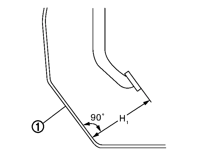
H1 : Refer to Brake Pedal .

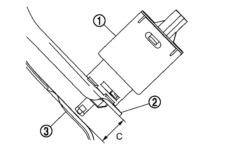
Stop Lamp Switch

Check the clearance (C) among the lever and the stop lamp switch mounting bracket .

C : Refer to Brake Pedal .

Depressed Brake Pedal Height

Check the height between the floor panel and the brake pedal upper surface (H2) when depressing the brake pedal at 490 N (50 kg, 110 lb) while engine ON.
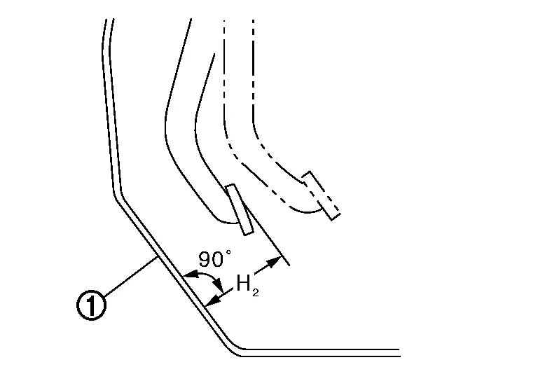
H2 : Refer to Brake Pedal .

ADJUSTMENT

Stop Lamp Switch

Remove instrument lower panel. Refer to Removal & Installation .

Disconnect the stop lamp switch harness connector.

Loosen the stop lamp switch 90° counterclockwise.

The stop lamp switch penetrate the clip hole of stop lamp switch mounting bracket and firmly push the stop lamp switch against the lever . (Do not touch the pedal during installing stop lamp switch.) And, turn the stop lamp switch clockwise (about 90°) until the stop lamp switch.
Brake Fluid Nissan Ariya

BRAKE FLUID : Inspection

BRAKE FLUID LEVEL

  • Check that the brake fluid level in the reservoir tank is within the standard (between MAX − MIN lines).
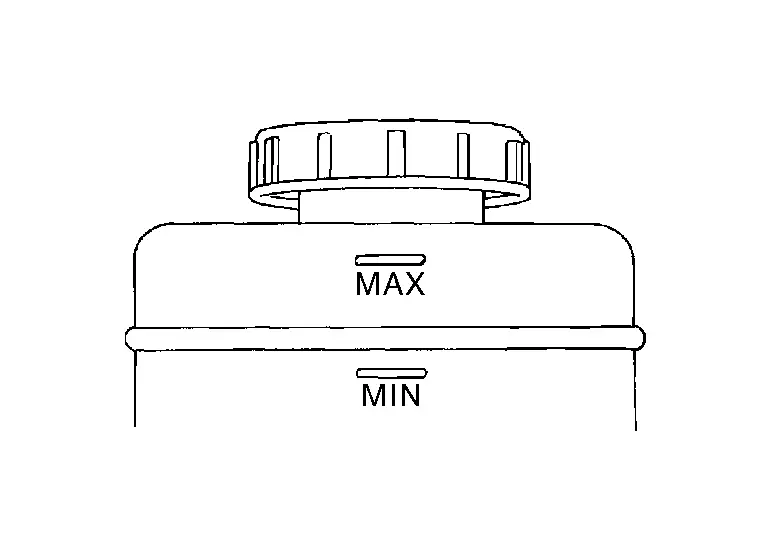
  • Visually check for any brake fluid leakage around the reservoir tank.

  • Check the brake system for any leakage if the fluid level is extremely low (lower than MIN).

  • Check the brake system for fluid leakage if the warning lamp remains illuminated even after the parking brake is released.

  • Check the reservoir tank for the mixing of foreign matter (e.g. dust) and oils other than brake fluid.

BRAKE LINE

Check brake line (tubes and hoses) for cracks, deterioration or other damage. Replace any damaged parts.

Depress the brake pedal with a force of 785 N (80 kg, 176 lb) and hold down the pedal for approximately 5 seconds with the engine running. Check for any fluid leakage.

BRAKE FLUID : Draining

Connect a vinyl tube to the bleed valve.
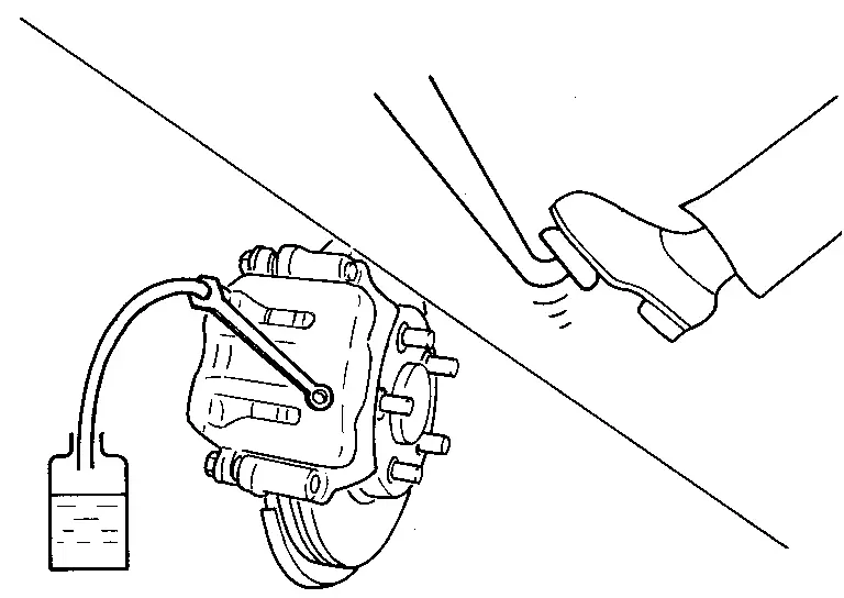
Depress the brake pedal and loosen the bleeder valve to gradually discharge brake fluid.

BRAKE FLUID : Refilling

Check that there is no foreign material in the reservoir tank, and refill with new brake fluid.

Loosen the bleeder valve, slowly depress the brake pedal to the full stroke, and then release the pedal. Repeat this operation at intervals of 2 or 3 seconds until new brake fluid is discharged. Then close the bleeder valve with the brake pedal depressed. Repeat the same work on each wheel.

Perform the air bleeding. Refer to Bleeding Brake System.

BRAKE FLUID : Air Bleeding

Connect a vinyl tube to the bleeder valve of the rear right brake.

Fully depress the brake pedal 4 to 5 times.

Loosen the bleeder valve and bleed air with the brake pedal depressed, and then quickly tighten the bleeder valve.

Repeat steps 2 and 3 until all of the air is out of the brake line.

In case of rear brake caliper with electric parking brake system, operate parking brake 5 times to bleed the air.

Tighten the bleeder valve to the specified torque.

  • Front disc brake: Refer to Exploded View .

  • Rear disc brake: Refer to Exploded View.

Perform steps 2 to 6. Occasionally fill with the brake fluid in order to keep it in the reservoir tank at least half of MAX line. Bleed air in the following order: rear right brake → front left brake → rear left brake → and front right brake in order.

Check that the fluid level in the reservoir tank is within the specified range after air bleeding. Refer Brake Fluid.

Check each item of brake pedal. Adjust it if the measurement value is not the standard. Refer Brake Pedal.

Electrically-Driven Intelligent Brake Unit Nissan Ariya

Inspection

Brake Fluid Leakage

Check for brake fluid leakage from the brake tube connections and the electrically-driven intelligent brake unit.

Front Brake Pad Nissan Ariya: FE0

FRONT BRAKE PAD : Periodic Maintenance Operation

Brake pad wear inspection

Check the brake pad thickness from the inspection hole in the cylinder body. Use a scale to check if necessary.
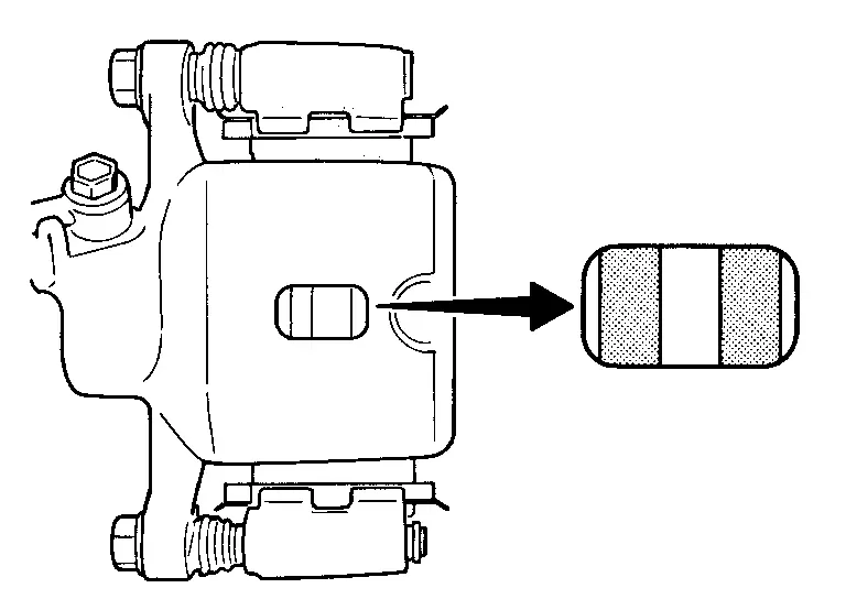
Wear limit thickness : Refer to Front Disc Brake.

ADJUSTMENT

If the brake pad is ground or replaced, or if there is an abnormal feel to the braking force, follow the procedure below and perform break-in work.

Drive on straight and flat roads.

Stop the vehicle by depressing the brake pedal to generate braking force that stops the Nissan Ariya vehicle in 3 to 5 seconds.

Cool the brakes.

Repeat steps 1 to 3 until the abnormal feel in braking force disappears.

Front Disc Rotor Nissan Ariya: FE0

FRONT DISC ROTOR : Periodic Maintenance Operation

INSPECTION

Appearance

Check surface of disc rotor for uneven wear, cracks, and serious damage. Replace it if necessary. Refer to Removal and Installation.

Runout

Fix the disc rotor to the wheel hub and bearing assembly with wheel nuts (2 points at least).

Check the wheel bearing axial end play. Refer to Inspection.

Inspect the runout with a dial indicator to measure at 10 mm (0.39 in) inside the disc edge.
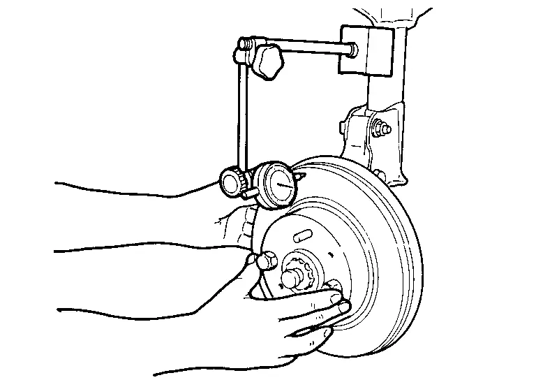
Runout (with it attached to the Nissan Ariya vehicle) : Refer to Front Disc Brake.

Find the installation position that has a minimum runout by shifting the disc rotor-to-wheel hub and bearing assembly installation position by one hole at a time if the runout exceeds the limit value.

Refinish the disc rotor if the runout is outside the limit even after performing the above operation.

Thickness

Check the thickness of the disc rotor using a micrometer. Replace the disc rotor if the thickness is below the wear limit. Refer to Removal and Installation.
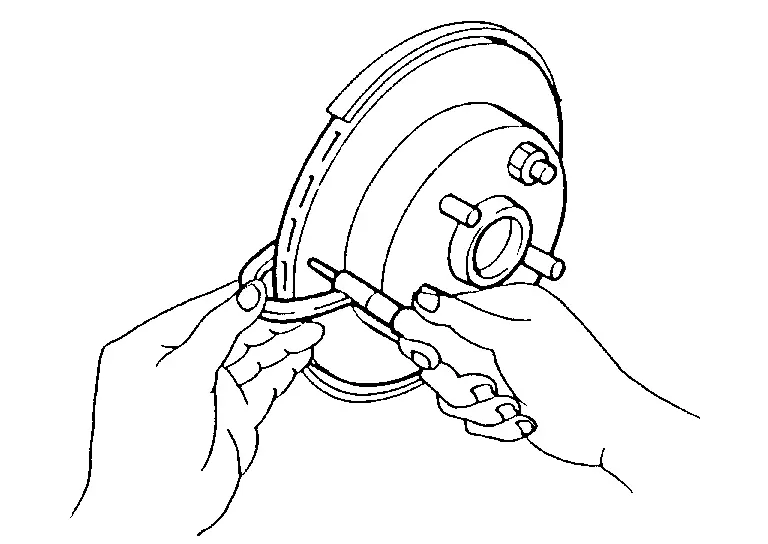
Wear thickness : Refer to Front Disc Brake.

ADJUSTMENT

Burnish contact surfaces between disc rotors and brake pads according to the following procedure after refinishing or replacing disc rotor, or if a soft pedal occurs at very low mileage.

Drive vehicle on straight, flat road.

Depress brake pedal with the power to stop vehicle within 3 to 5 seconds until the Nissan Ariya vehicle stops.

Drive without depressing brake for a few minutes to cool the brake.

Repeat steps 1 to 3 until pad and disc rotor are securely fitted.