Radiator
- 2wd Models
- Awd Models
2wd Models Nissan Ariya 2023
RADIATOR : Exploded View
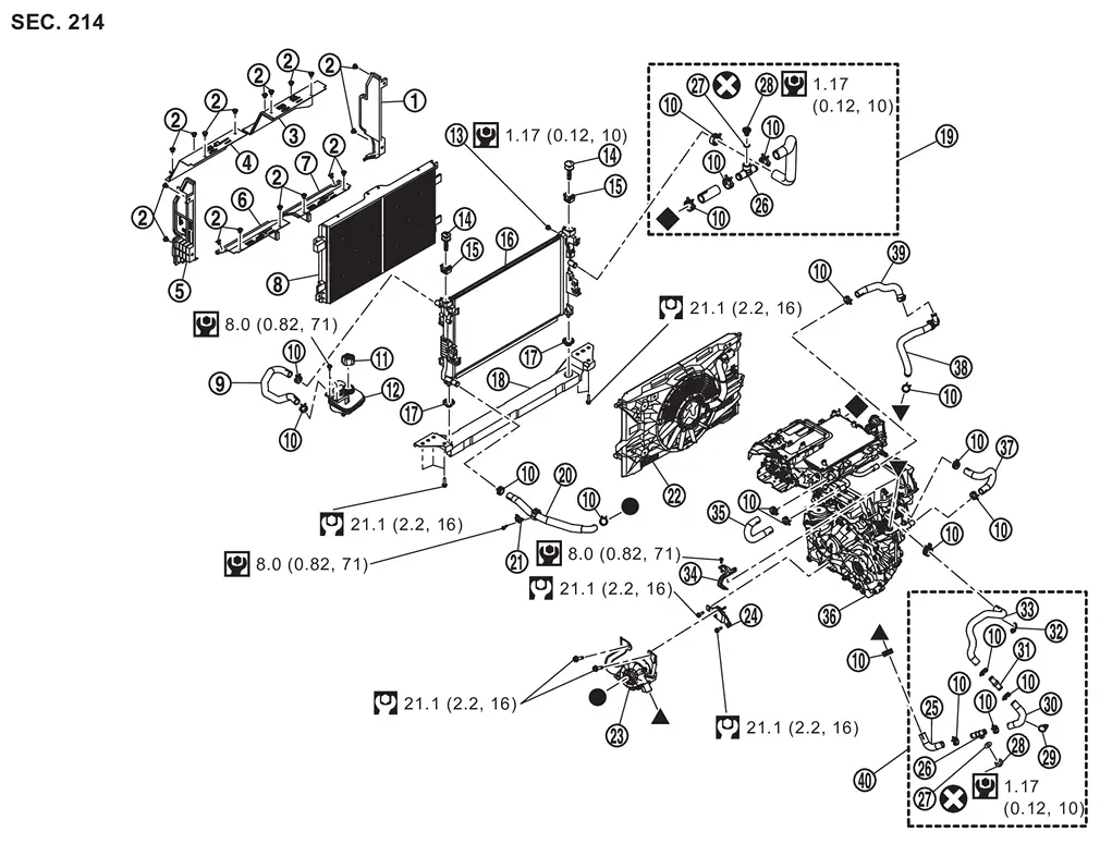
 |
Radiator air guide right |  |
Clip |  |
Radiator air guide upper right |
 |
Radiator air guide upper left |  |
Radiator air guide left |  |
Radiator air guide lower left |
 |
Radiator air guide lower right |  |
Chipping guard |  |
Radiator reservoir tank hose |
 |
Clamp |  |
Reservoir tank cap |  |
Reservoir tank |
 |
Air bleeder |  |
Radiator upper mounting lock |  |
Radiator upper mounting |
 |
Radiator |  |
Radiator lower mounting |  |
Radiator core support lower |
 |
Radiator outlet hose |  |
Radiator hose lower |  |
Radiator hose lower bracket |
 |
Radiator cooling fan shroud |  |
Electric water pump |  |
Electric water pump bracket |
 |
Radiator hose lower (between traction motor inverter and electric water pump 1)*1 |  |
Radiator hose lower connector |  |
O-ring |
 |
Drain plug |  |
Clip 1 |  |
Radiator hose lower (between traction motor inverter and electric water pump 2)*1 |
 |
Radiator hose lower pipe *1 |  |
Clip 2 |  |
Radiator hose lower (between traction motor inverter and electric water pump 3)*1 |
 |
Bracket |  |
DC/DC converter inlet hose |  |
Traction motor |
 |
Traction motor inlet hose |  |
Traction motor inlet hose (traction motor side) |  |
Traction motor inlet hose (DC/DC converter side) |
 |
Radiator hose lower ASSY (between traction motor inverter and electric water pump) | *1 :,,, are supplied as an assembly |
|||
 |
: N·m(kg-m, in-lb) | ||||
 |
: N·m(kg-m, ft-lb) | ||||
 ,  ,  ,  : Shows the connection between the same marks. |
|||||
RADIATOR : Removal & Installation
REMOVAL
Remove high voltage supply unit from vehicle. Refer to HIGH VOLTAGE POWER DELIVERY ASSEMBLY : Exploded View.
Discharge A/C refrigerant gas. Refer to Recycle Refrigerant.
Remove A/C piping mounting bolts  and remove piping.
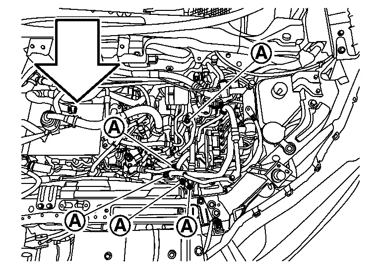
 |
: Nissan Ariya Vehicle front |
Remove harness connector .
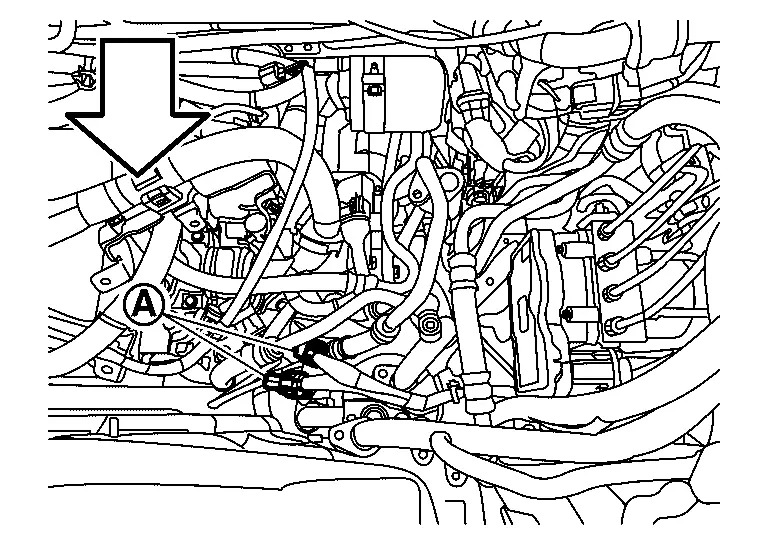
|
: Nissan Ariya Vehicle front |
Remove front bumper. Refer to Removal & Installation.
Remove active grill shutter. Refer to Removal & Installation.
Remove radiator air guides upper on both sides.
Remove radiator air guides lower on both sides.
Remove radiator air guides on both sides.
Remove chipping guard.
Remove high pressure flexible pipe ASSY. Refer to Removal & Installation.
Remove accumulator ASSY side of low pressure flexible hose. Refer to Removal & Installation.
Remove high pressure flexible hose. Refer to Removal & Installation.
Remove radiator reservoir tank hose.
Remove harness and harness clips of radiator cooling fan motor. Refer to COOLING FAN : Removal & Installation.
Remove radiator outlet hose.
Remove radiator hose lower.
Remove bolts of radiator hose lower bracket.
Remove bracket mounting bolts. Refer to FRONT TRACTION MOTOR : Removal & Installation.
Remove radiator upper mounting lock.
Remove radiator, condenser, cooling fan, and accumulator ASSY all together from Nissan Ariya vehicle.
Remove accumulator ASSY from condenser, and radiator cooling fan shroud.
Remove radiator cooling fan shroud from radiator.
Remove radiator from condenser.
Disconnect each hose from radiator.
INSTALLATION
Note the following, and install in the reverse order of removal.
Radiator
Chipping Guard
When installing the chipping guard, securely insert the engaging points shown by the arrows (
 ) in the figure.
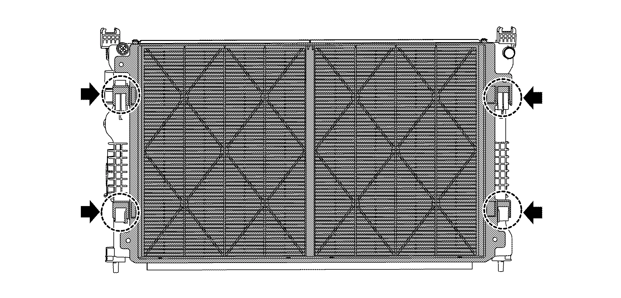
Radiator Hose / Water Hose
When inserting the radiator hose and water hose , insert all the way until it contacts double spool
, or it contacts the end.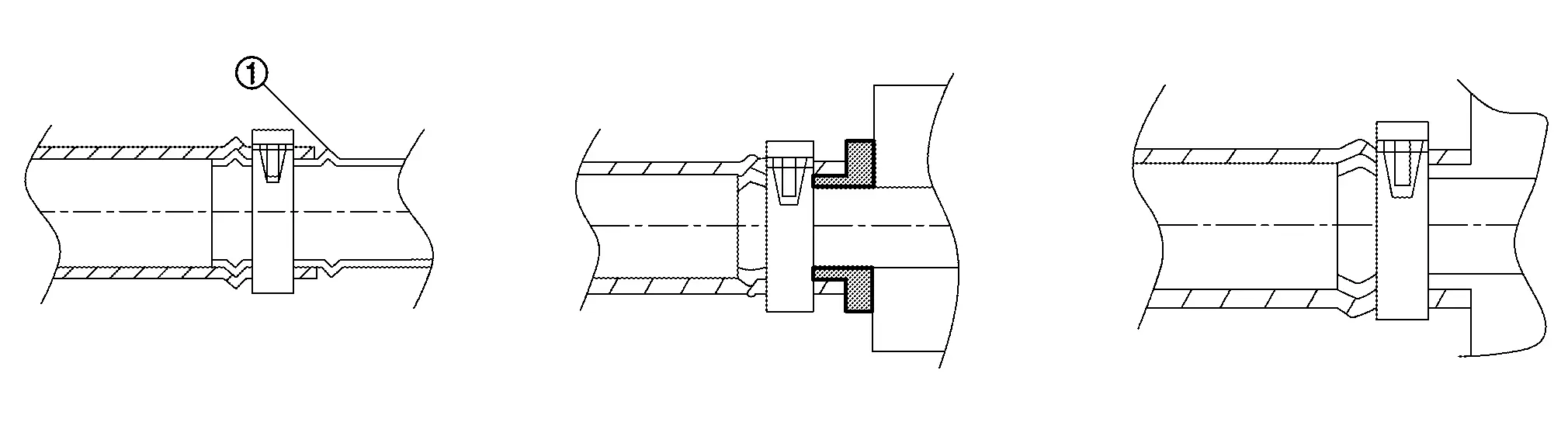
Refer to the following table when installing the hose clamps.
Location of hose Hose end Direction of Paint mark Direction of hose clamp tabs
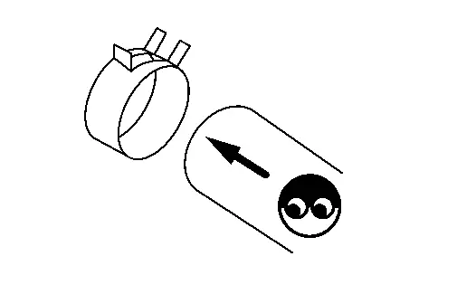 : Nissan Ariya Vehicle upper
 Vehicle front
Radiator reservoir tank hose Radiator reservoir tank side Nissan Ariya Vehicle upper 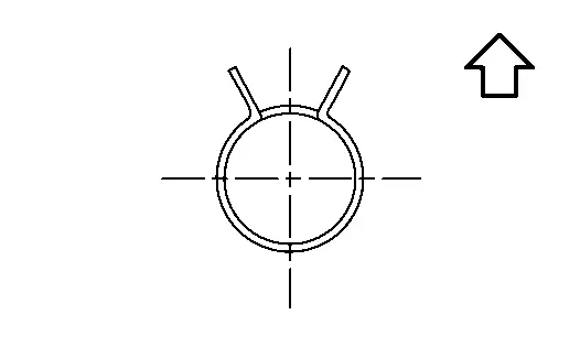
Radiator side Nissan Ariya Vehicle upper 
Radiator outlet hose Radiator side Nissan Ariya Vehicle right 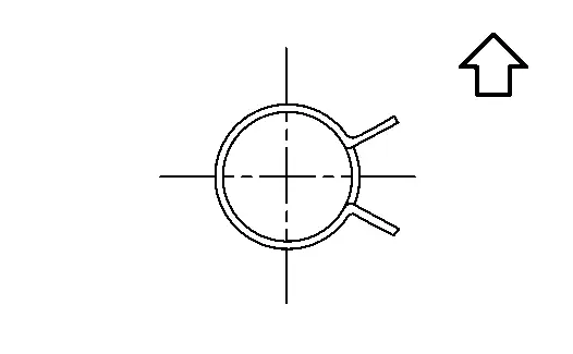
In-Nissan Ariya vehicle charger side Vehicle upper DC/DC converter inlet hose In-Nissan Ariya vehicle charger side Vehicle rear DC/DC converter side Nissan Ariya Vehicle rear Traction motor inlet hose (DC/DC converter side) DC/DC converter side Nissan Ariya Vehicle rear 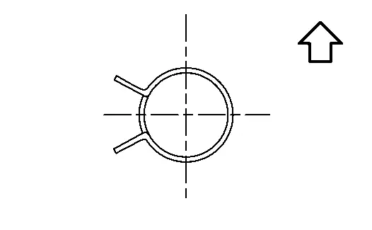
Traction motor inlet hose (traction motor side) Nissan Ariya Vehicle right Traction motor inlet hose Traction motor inverter side Nissan Ariya Vehicle upper Traction motor inside Nissan Ariya Vehicle rear Radiator hose lower (between traction motor inverter and electric water pump) Traction motor inverter side Nissan Ariya Vehicle upper Electric water pump side Nissan Ariya Vehicle rear left 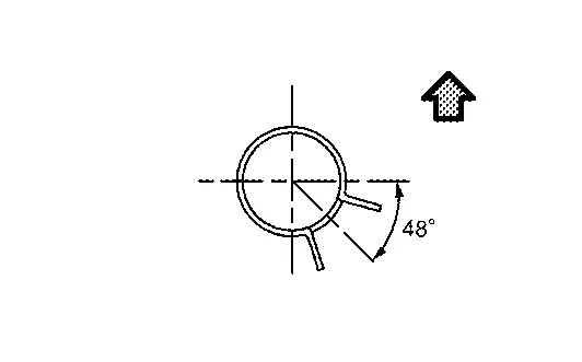
Radiator hose lower Electric water pump side Nissan Ariya Vehicle upper Radiator side Nissan Ariya Vehicle left Traction motor inlet hose (traction motor side) Traction motor inside Nissan Ariya Vehicle upper right 
Traction motor inlet hose (DC/DC converter side) Nissan Ariya Vehicle upper The direction of the hose clamp tabs must be within ±30°
 of the indicated position .
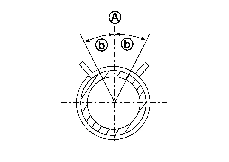
When installing hose clamp
, check that the distance “A” between the end of the radiator hose paint mark and the hose clamp is within the specified range.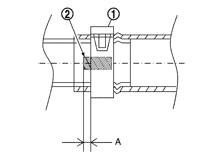
Dimension “A” : (+1) - (-1) mm [(+0.04) - (-0.04) in]
RADIATOR : Inspection
INSPECTION AFTER INSTALLATION
Confirm that the reservoir tank cap is tightened.
With a suitable tool, check that there is no leaks of coolant. Refer to Inspection.
Start the electric pump, and check the joints for coolant leaks.
Awd Models Nissan Ariya: FE0
RADIATOR : Exploded View
Front side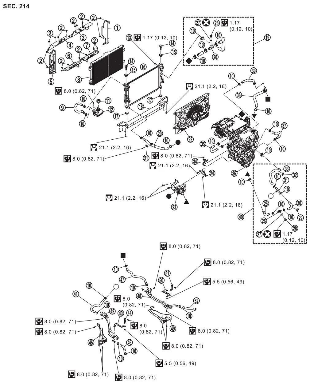
|
Radiator air guide | |
Clip | |
Radiator air guide upper right |
|
Radiator air guide upper left | |
Radiator air guide left | |
Radiator air guide lower left |
|
Radiator air guide lower right | |
Chipping guard | |
Radiator reservoir tank hose |
|
Clamp | |
Reservoir tank cap | |
Reservoir tank |
|
Air bleeder | |
Radiator upper mounting lock | |
Radiator upper mounting |
|
Radiator | |
Radiator lower mounting | |
Radiator core support lower |
|
Radiator outlet hose | |
Radiator hose lower | |
Radiator hose lower bracket |
|
Radiator cooling fan shroud | |
Electric water pump | |
Electric water pump bracket |
|
Radiator hose lower (Between traction motor inverter and electric water pump 1)*1 | |
Radiator hose lower connector | |
O-ring |
|
Drain plug | |
Clip 1 | |
Radiator hose lower (Between traction motor inverter and electric water pump 2)*1 |
|
Radiator hose lower pipe *2 | |
Clip 2 | |
Radiator hose lower (Between traction motor inverter and electric water pump 3)*3 |
|
Bracket | |
DC/DC converter inlet hose | |
Traction motor |
|
Traction motor inlet hose | |
Traction motor inlet hose (Traction motor side) | |
Traction motor inlet hose (DC/DC converter side) |
|
Radiator hose lower [Between inverter(front) and electric water pump] ASSY |  |
Water hose 1 |  |
Electric water pump inlet tube ASSY left |
 |
Water hose bracket 2 |  |
Water hose bracket 1 |  |
Electric water pump inlet tube ASSY cover left |
 |
Water hose 2 |  |
Water hose 3 |  |
Electric water pump inlet tube ASSY right |
 |
Electric water pump inlet tube ASSY cover right |  |
Water hose bracket3 |  |
Water hose bracket 4 |
 |
Water hose 4 | ||||
| *1 | ,,, are supplied as an assembly |
||||
|
: N·m (kg-m, in-lb) | ||||
|
: N·m (kg-m, ft-lb) | ||||
,, ,,,  : Shows the connection between the same marks |
|||||
Rear side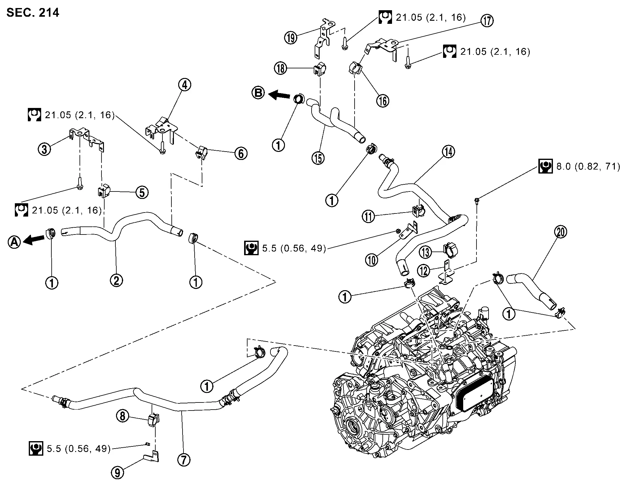
|
Clamp | |
Water hose [inverter (rear) inlet] 2 | |
Bracket 1 |
|
Bracket 2 | |
Clip 1 | |
Clip 2 |
|
Water hose [inverter (rear) inlet] 1 | |
Clip 3 | |
Bracket 3 |
|
Bracket 4 | |
Clip 4 | |
Bracket 5 |
|
Clip 5 | |
Water hose (oil cooler outlet) 1 | |
Water hose (oil cooler outlet) 2 |
|
Clip 6 | |
Bracket 6 | |
Clip 7 |
|
Bracket 7 | |
Water hose [inverter (rear) inlet - oil cooler] | ||
|
To Li-ion batery |  |
To Li-ion batery | ||
|
: N·m (kg-m, in-lb) | ||||
|
: N·m (kg-m, ft-lb) |
RADIATOR : Removal & Installation
REMOVAL
water line front side
Remove high voltage supply unit from vehicle. Refer to HIGH VOLTAGE POWER DELIVERY ASSEMBLY : Exploded View.
Discharge A/C refrigerant gas. Refer to Recycle Refrigerant.
Remove A/C piping mounting bolts and remove piping.
|
: Nissan Ariya Vehicle front |
Remove harness connector .
|
: Nissan Ariya Vehicle front |
Remove front bumper. Refer to Removal & Installation.
Remove active grill shutter. Refer to Removal & Installation.
Remove radiator air guides upper on both sides.
Remove radiator air guides lower on both sides.
Remove radiator air guides on both sides.
Remove chipping guard.
Remove high pressure flexible pipe ASSY. Refer to Removal & Installation.
Remove accumulator ASSY side of low pressure flexible hose. Refer to Removal & Installation.
Remove high pressure flexible hose. Refer to Removal & Installation.
Remove radiator reservoir tank hose.
Remove harness and harness clips of radiator cooling fan motor. Refer to COOLING FAN : Removal & Installation.
Remove radiator outlet hose.
Remove radiator hose lower.
Remove bolts of radiator hose lower bracket.
Remove bracket mounting bolts. Refer to FRONT TRACTION MOTOR : Removal & Installation.
Remove radiator upper mounting lock.
Remove radiator, condenser, cooling fan, and accumulator ASSY all together from Nissan Ariya vehicle.
Remove accumulator ASSY from condenser, and radiator cooling fan shroud.
Remove radiator cooling fan shroud from radiator.
Remove radiator from condenser.
Disconnect each hose from radiator.
water line rear side
Drain coolant. Refer to COOLANT : Draining.
Remove the rear diffuser front. Refer to Exploded View.
Remove the li-ion battery under cover (rear). Refer to Exploded View.
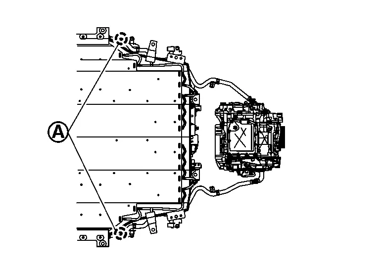
Remove the water hose [inverter (rear) inlet] 2 and the water hose (oil cooler outlet) 2 from the li-ion battery side
.
Remove the clip 1
, clip 2, clip 6 and clip 7.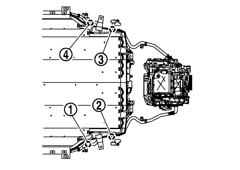
Remove the rear traction motor.
Remove the water hose [inverter (rear) inlet] 2 from the water hose [inverter (rear) inlet] 1 side.
Remove the water hose (oil cooler outlet) 2 from the water hose (oil cooler outlet) 1 side.
Remove the clip 3.
Remove the water hose [inverter (rear) inlet] 1 from the rear traction motor side.
Remove the clip 4 and clip 5.
Remove the water hose (oil cooler outlet) 1 from the rear traction motor side.
Remove the water hose [inverter (rear) inlet - oil cooler]
INSTALLATION
water line front side
Note the following, and install in the reverse order of removal.
When installing the chipping guard, securely insert the engaging points shown by the arrows (
) in the figure.
When inserting the radiator hose and water hose , insert all the way until it contacts double spool
, or it contacts the end.Refer to the following table when installing the hose clamps.
Location of hose Hose end Direction of Paint mark Direction of hose clamp tabs
: Nissan Ariya Vehicle upperVehicle frontRadiator reservoir tank hose Radiator reservoir tank side Nissan Ariya Vehicle upper Radiator side Nissan Ariya Vehicle upper Radiator outlet hose Radiator side Nissan Ariya Vehicle right In-Nissan Ariya vehicle charger side Vehicle upper DC/DC converter inlet hose In-Nissan Ariya vehicle charger side Vehicle rear DC/DC converter side Nissan Ariya Vehicle rear Traction motor inlet hose (DC/DC converter side) DC/DC converter side Nissan Ariya Vehicle rear Traction motor inlet hose (traction motor side) Nissan Ariya Vehicle right Traction motor inlet hose Traction motor inverter side Nissan Ariya Vehicle upper Traction motor inside Nissan Ariya Vehicle rear Radiator hose lower (between traction motor inverter and electric water pump) Traction motor inverter side Nissan Ariya Vehicle upper Electric water pump side Nissan Ariya Vehicle rear left Radiator hose lower Electric water pump side Nissan Ariya Vehicle upper Radiator side Nissan Ariya Vehicle left Traction motor inlet hose (traction motor side) Traction motor inside Nissan Ariya Vehicle upper right Traction motor inlet hose (DC/DC converter side) Nissan Ariya Vehicle upper The direction of the hose clamp tabs must be within ±30°
of the indicated position .When installing hose clamp
, check that the distance “A” between the end of the radiator hose paint mark and the hose clamp is within the specified range.Dimension “A” :(+1) - (–1) mm [(+0.04) - (-0.04) in]
water line rear side
When inserting the radiator hose and water hose , insert all the way until it contacts double spool
, or it contacts the end.Refer to the following table when installing the hose clamps.
Location of hose Hose end Direction of Paint mark Direction of hose clamp tabs
: Nissan Ariya Vehicle upperVehicle frontWater hose [inverter (rear) inlet] 2 Li-ion battery side Nissan Ariya Vehicle left Water hose [inverter (rear) inlet] 1 side Nissan Ariya Vehicle left 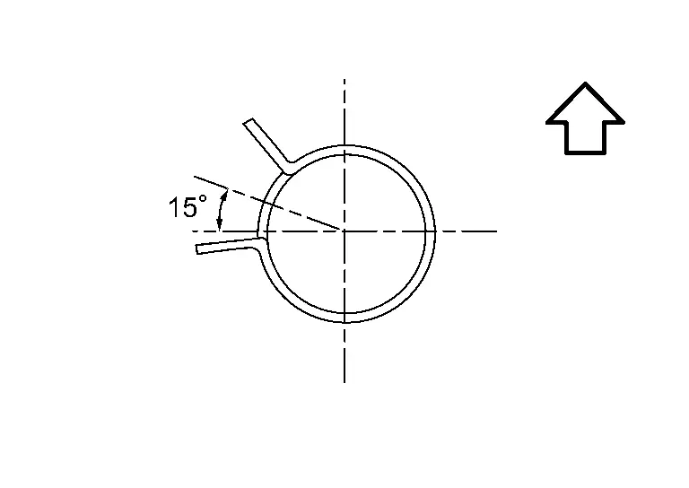
Water hose [inverter (rear) inlet] 1 Rear traction motor inverter side Nissan Ariya Vehicle upper - - - Water hose (oil cooler outlet) 1 Rear traction motor side Nissan Ariya Vehicle upper - - - Water hose (oil cooler outlet) 2 Li-ion battery side Nissan Ariya Vehicle right Water hose (oil cooler outlet) 1 side Nissan Ariya Vehicle right 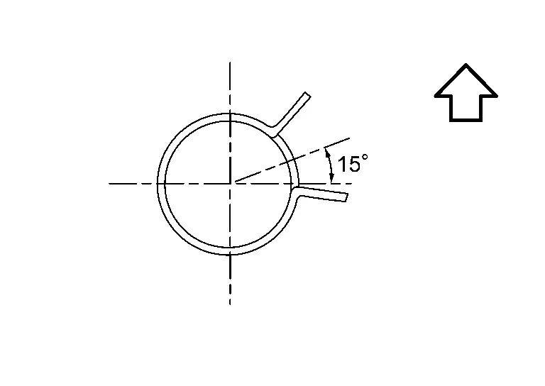
Water hose [inverter (rear) inlet - oil cooler] Rear traction motor inverter side Nissan Ariya Vehicle upper Rear traction motor side Nissan Ariya Vehicle upper The direction of the hose clamp tabs must be within ±30°
of the indicated position .When installing hose clamp
, check that the distance “A” between the end of the radiator hose paint mark and the hose clamp is within the specified range.Dimension “A” : (+1) - (-1) mm [(+0.04) - (-0.04) in]
Inspection
INSPECTION AFTER INSTALLATION
Confirm that the reservoir tank cap is tightened.
With a suitable tool, check that there is no leaks of coolant. Refer to Inspection.
Start the electric pump, and check the joints for coolant leaks.