Ecu Diagnosis Information

In this manual: Ecu Diagnosis Information
How to Use This Manual — 1Precautions — 1Preparation — 1Vehicle Information — 1Basic Inspection — 1Preparation. Commercial Service Tools Or/and Repair Part — 1Description — 1Component Parts — 1System — 1Diagnosis System (vcm) — 1Ecu Diagnosis Information. Vcm — 1Ev Control System — 1Ev/hev (vcm) — 1Component Parts /circuit Diagnosis — 1Ev Control System — 1Periodic Maintenance. Ev System Warning Lamp — 1Removal and Installation. Vcm — 1Traction Motor System :: Front Traction Motor — 1Preparation — 1Description — 4Basic Inspection — 2Dtc Diagnosis — 2Component Parts /circuit Diagnosis — 1Traction Motor System :: Rear Traction Motor — 1Description — 4Basic Inspection — 2Dtc Diagnosis — 2Component Parts /circuit Diagnosis — 1Removal and Installation — 1Ev Battery System :: 66kwh Li-Ion Battery — 1Description — 4Basic Inspection — 2Dtc Diagnosis — 2Component Parts /circuit Diagnosis — 1Removal and Installation — 1Disassembly and Assembly — 2Service Data — 1Ev Battery System :: 91kwh Li-Ion Battery — 1Description — 4Basic Inspection — 2Dtc Diagnosis — 2Component Parts /circuit Diagnosis — 1Removal and Installation — 1Disassembly and Assembly — 1Service Data — 2Preparation. Vehicle Charging System — 1Vehicle Charging System :: Description — 1Component Parts — 2System — 1Diagnosis System (on-Board Charger) — 1Diagnosis System (dc/dc Converter) — 1Ecu Diagnosis Information — 1Vehicle Charging System — 1Charger/pd Module (on-Board Charger) — 1Cplc (cplc) — 1Dcdc (dc/dc Converter) — 1Component Parts/circuit Diagnosis — 1Symptom Diagnosis — 1Evse Inspection — 1Periodic Maintenance — 1Removal and Installation — 1Disassembly and Assembly — 1Preparation. High Voltage Cooling System — 1Description — 1Symptom Diagnosis. Overheating Cause Analysis — 1Periodic Maintenance — 1Coolant — 1Removal and Installation — 1Radiator — 1Service Data — 1Removal and Installation. Accelerator Control System — 1Reduction Gear: Re1f62a — 1Removal and Installation — 1Transaxle & Transmission :: Electric Shift — 1Description — 3Basic Inspection — 2Dtc Diagnosis — 2Component Parts /circuit Diagnosis — 1Removal and Installation — 1Rear Final Drive: Rn1r62a — 1Removal and Installation — 1Preparation. Front Axle System — 1Symptom Diagnosis. Noise, Vibration and Harshness (nvh) Troubleshooting — 1Periodic Maintenance — 1Removal and Installation — 1Service Data. Front Drive Shaft — 12wd — 14wd — 1Periodic Maintenance — 1Removal and Installation — 1Preparation. Front Suspension System — 1Symptom Diagnosis. Noise, Vibration and Harshness (nvh) Troubleshooting — 1Periodic Maintenance — 1Removal and Installation — 1Service Data — 1Symptom Diagnosis. Noise, Vibration and Harshness (nvh) Troubleshooting — 1Periodic Maintenance — 1Removal and Installation — 1Service Data — 1Preparation. Road Wheels & Tires System — 1Description — 1System — 1Ecu Diagnosis Information. Bcm (body Control Module) — 1Tpms — 1Dtc/circuit Diagnosis — 1Symptom Diagnosis — 1Periodic Maintenance. Road Wheels & Tires — 1Removal and Installation — 1Service Data — 1Preparation. Brake System — 1System Description — 1Component Parts — 1Ecu Diagnosis Information. Electrically-Driven Intelligent Brake Unit — 1Basic Inspection — 1Dtc/circuit Diagnosis — 1Symptom Diagnosis — 1Periodic Maintenance — 1Removal and Installation — 1Service Data — 1Preparation. Parking Brake System — 1System Description — 1Component Parts — 1System — 1Ecu Diagnosis Information. Abs Actuator and Electric Unit (control Unit) — 1Basic Inspection. Diagnosis and Repair Work Flow — 1Component Parts /circuit Diagnosis — 1Symptom Diagnosis — 1Removal and Installation — 1Brake Control System :: With Vdc — 1System Description — 3Basic Inspection — 2Dtc/circuit Diagnosis — 1Symptom Diagnosis — 2Removal and Installation — 1Brake Control System :: Automatic Brake Hold — 1System Description — 3Component Parts /circuit Diagnosis — 1Removal and Installation — 1Brake Control System :: E-Step — 1System Description — 3Removal and Installation — 1System Description — 1Ecu Diagnosis Information — 1Basic Inspection — 1Symptom Diagnosis — 1Rear Automatic Braking — 1System Description — 1Basic Inspection — 1Preparation. Steering System — 1System Description — 1Component Parts — 1Basic Inspection — 1Dtc/circuit Diagnosis — 1Symptom Diagnosis — 1Periodic Maintenance. Steering Wheel — 1Removal and Installation — 1Service Data — 1System Description — 1Component Parts — 1Steering Control System — 1Ecu Diagnosis Information. Power Steering Control Module — 1Dtc/circuit Diagnosis — 1Component Parts /circuit Diagnosis — 1Symptom Diagnosis — 1Removal and Installation. Power Steering Control Module — 1System Description — 1Removal and Installation — 1System Description — 1System — 1Basic Inspection. Diagnosis and Repair Work Flow — 1Dtc/circuit Diagnosis — 1Symptom Diagnosis — 1Component Parts — 1Basic Inspection — 1Removal and Installation — 1System Description — 1System — 1Ecu Diagnosis Information. Air Bag Diagnosis Sensor Unit — 1Basic Inspection — 1Dtc/circuit Diagnosis — 1Symptom Diagnosis — 1System Description. Description. Ventilation System — 1Removal and Installation — 1Preparation. Preparation — 1System Description — 1Basic Inspection — 1Symptom Diagnosis — 1Removal and Installation — 1Electric Compressor — 1Cooler Pipe and Hose — 1A/c Unit Assembly Cover — 1A/c Unit Assembly — 1Heater & Air Conditioning Control System :: Automatic Air Conditioning — 1System Description — 1Ecu Diagnosis Information — 1Basic Inspection — 2Dtc Diagnosis — 1Symptom Diagnosis — 1Removal and Installation — 2Preparation. Preparation — 1Symptom Diagnosis. Squeak and Rattle Trouble Diagnoses — 1Removal and Installation — 1Preparation. Instrument Panel — 1Component Parts — 1System — 1Ecu Diagnosis Information. Flexible Center Storage Control Module — 1Basic Inspection. Diagnosis and Repair Work Flow — 1Dtc/circuit Diagnosis — 1Symptom Diagnosis — 1Removal and Installation — 1Preparation. Preparation — 1Component Parts — 1System — 1Ecu Diagnosis Information. Driver Lumbar Support Control Module — 1Basic Inspection. Diagnosis and Repair Work Flow — 1Dtc/circuit Diagnosis — 1Symptom Diagnosis — 1Removal and Installation — 1System Description — 1System — 1Ecu Diagnosis Information — 1Basic Inspection — 1Dtc/circuit Diagnosis — 1Symptom Diagnosis — 1Manual Function Does Not Operate — 1Memory Function Does Not Operate — 1Removal and Installation — 1Preparation. Preparation — 1System Description — 1System (intelligent Key System) — 1Diagnosis System (bcm) — 1Ecu Diagnosis Information — 1Basic Inspection — 1Dtc/circuit Diagnosis — 1U2141-87 Can Comm Circuit — 1Power Supply and Ground Circuit — 1Symptom Diagnosis — 1Automatic Back Door Operation Does Not Operate — 1Back Door Does Not Open — 1Door Does Not Lock/unlock with Door Lock and Unlock Switch — 1Removal and Installation — 1Hood — 1Radiator Core Support — 1Charge Port Lid — 1Front Fender — 1Front Door — 1Rear Door — 1Back Door — 1Hood Lock — 1Front Door Lock — 1Rear Door Lock — 1Back Door Lock — 1Outside Key Antenna — 1System Description — 1System — 1Ecu Diagnosis Information. Inverter (front), Inverter (rear), Bcm, Intelligent Key Unit — 1Basic Inspection — 1Dtc/circuit Diagnosis — 1Symptom Diagnosis — 1Preparation — 1Symptom Diagnosis. Squeak and Rattle Trouble Diagnoses — 1Removal and Installation — 1System Description — 1Ecu Diagnosis Information — 1Basic Inspection — 1Dtc/circuit Diagnosis — 1Power Supply and Ground Circuit — 1Symptom Diagnosis — 1Front Passenger Side Power Window Does Not Operate — 1Rear Lh Side Power Window Does Not Operate — 1Rear Rh Side Power Window Does Not Operate — 1Removal and Installation. Power Window Main Switch — 1Preparation. Preparation — 1System Description — 1Ecu Diagnosis Information — 1Basic Inspection — 1Dtc/circuit Diagnosis — 1Power Supply and Ground Circuit — 1Sunroof Switch Assembly — 1Symptom Diagnosis — 1Auto Operation Does Not Operate — 1Removal and Installation — 1Preparation — 1Description — 1Symptom Diagnosis. Squeak and Rattle Trouble Diagnoses — 1Removal and Installation — 1Service Information — 6Repair Information — 1Precaution — 1Preparation — 1Removal and Installation — 1Service Data — 1Preparation. Preparation — 1Component Parts — 1System — 1Ecu Diagnosis Information — 1Wiring Diagram. Door Mirror — 1Basic Inspection. Diagnosis and Repair Work Flow — 1Dtc/circuit Diagnosis — 1Power Supply and Ground Circuit — 1Symptom Diagnosis — 1Removal and Installation — 1Exterior Lighting System :: Led Headlamp — 1System Description — 3Basic Inspection — 1Dtc/circuit Diagnosis — 1Symptom Diagnosis — 1Periodic Maintenance — 1Removal and Installation — 1System Description — 1System — 1Diagnosis System (bcm) — 1Ecu Diagnosis Information. Bcm, Intelligent Key Unit — 1Basic Inspection. Diagnosis and Repair Work Flow — 1Dtc/circuit Diagnosis — 1Symptom Diagnosis. Interior Lighting System Symptom — 1Removal and Installation — 1Service Data. Bulb Specifications — 1System Description — 1System — 1Ecu Diagnosis Information. Bcm, Ipdm E/r — 1Basic Inspection. Diagnosis and Repair Work Flow — 1Dtc/circuit Diagnosis — 1Symptom Diagnosis — 1Removal and Installation — 1System Description — 1Ecu Diagnosis Information. Bcm — 1Basic Inspection. Diagnosis and Repair Work Flow — 1Dtc/circuit Diagnosis — 1Symptom Diagnosis — 1Removal and Installation — 1Preparation. Preparation — 1Removal and Installation. Horn — 1Preparation. Commercial Service Tools Or/and Repair Part — 1System Description — 1Component Parts — 1Ecu Diagnosis Information. Approaching Vehicle Sound for Pedestrians (vsp) Control Unit — 1Approaching Vehicle Sound for Pedestrians (vsp) — 1Vsp [approaching Vehicle Sound for Pedestrians (vsp) Control Unit] — 1Approaching Vehicle Sound for Pedestrians (vsp) System — 1Removal and Installation — 1Removal and Installation — 1Wireless Charger — 1System Description — 1Basic Inspection — 1Dtc/circuit Diagnosis — 1Removal and Installation — 1Component Parts — 1System — 1Diagnosis System (bcm) — 1Ecu Diagnosis Information. Bcm — 1Basic Inspection — 1Dtc/circuit Diagnosis — 1Symptom Diagnosis — 1Removal and Installation — 1Can Fundamental — 1Description — 1Trouble Diagnosis — 1Can (controller Area Network) — 1Description — 1
~6min read
  • Bcm
  • Power Window Main Switch
  • Front Power Window Motor (driver Side)
  • Front Power Window Motor (passenger Side)

Bcm Nissan Ariya SUV

List of ECU Reference

ECUReference
BCM Reference Value
Fail-safe
DTC Inspection Priority Chart
DTC Index

Power Window Main Switch Nissan Ariya 1st generation

Reference Value (Without Automatic Drive Positioner)

TERMINAL LAYOUT

PHYSICAL VALUES

Terminal No.

(Wire color)
DescriptionConditionValue
+–Signal nameInput/Output

3

(GR)
Ground Auto ACC power supply Input Power switch OFF (auto ACC status) or ON 9 – 16 V

4

(L)
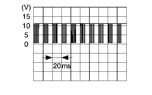
Ground LIN communication signal Input/ Output Power switch ON

6

(V)
Ground Door mirror motor (driver side) UP output signal Output Door mirror (driver side) Operate (UP) 9 – 16 V
Other than above 0 - 1 V

7

(BG)
Ground Door mirror motor (passenger side) DOWN/RIGHT output signal Output Door mirror (passenger side) Operate (DOWN/RIGHT) 9 – 16 V
Other than above 0 - 1 V

8

(P)
Ground Door mirror motor (passenger side) UP output signal Output Door mirror (passenger side) Operate (UP) 9 – 16 V
Other than above 0 - 1 V

9

(G)
Ground Door mirror motor (passenger side) LEFT output signal Output Door mirror (passenger side) Operate (LEFT) 9 – 16 V
Other than above 0 – 1 V

10

(Y)
Ground Door mirror motor (driver side) LEFT output signal Output Door mirror (driver side) Operate (LEFT) 9 – 16 V
Other than above 0 – 1 V

13

(SB)
Ground Front power window motor (driver side) DOWN signal (for submersion) Output Power switch OFF (auto ACC status) or ON 9 – 16 V
Power switch OFF (not auto ACC status) 0 – 1 V

17

(V)
Ground Door mirror motor (driver side) OPEN output signal Output Door mirror (driver side) Operate (OPEN) 9 – 16 V
Other than above 0 – 1 V

18

(G)
Ground Door mirror motor (driver side) CLOSE output signal Output Door mirror (driver side) Operate (CLOSE) 9 – 16 V
Other than above 0 – 1 V

19

(LA/R)
Ground Door mirror motor (passenger side) CLOSE output signal Output Door mirror (passenger side) Operate (CLOSE) 9 – 16 V
Other than above 0 – 1 V

20

(LA/Y)
Ground Door mirror motor (passenger side) OPEN output signal Output Door mirror (passenger side) Operate (OPEN) 9 – 16 V
Other than above 0 – 1 V

21

(BR)
Ground Door mirror motor (driver side) DOWN/RIGHT output signal Output Door mirror (driver side) Operate (DOWN/RIGHT) 9 – 16 V
Other than above 0 – 1 V

22

(B)
Ground Ground — — 0 – 1 V

Reference Value (With Automatic Drive Positioner)

TERMINAL LAYOUT

PHYSICAL VALUES

Terminal No.

(Wire color)
DescriptionConditionValue
+–Signal nameInput/Output

2

(R)
Ground Door mirror sensor power supply Output — 4 - 6 V

3

(GR)
Ground Auto ACC power supply Input Power switch OFF (auto ACC status) or ON 9 – 16 V

4

(L)
Ground LIN communication signal Input/ Output Power switch ON

6

(V)
Ground Door mirror motor (driver side) UP output signal Output Door mirror (driver side) Operate (UP) 9 – 16 V
Other than above 0 - 1 V

7

(LG)
Ground Door mirror sensor (driver side) UP/DOWN signal Input Door mirror (driver side) Change between 2 V (close to left edge) - 0 V (close to right edge)

8

(L)
Ground Door mirror sensor (driver side) LEFT/RIGHT signal Input Door mirror (driver side) Change between 6 V (close to left edge) - 0 V (close to right edge)

10

(Y)
Ground Door mirror motor (driver side) LEFT output signal Output Door mirror (driver side) Operate (LEFT) 9 – 16 V
Other than above 0 – 1 V

13

(SB)
Ground Front power window motor (driver side) DOWN signal (for submersion) Output Power switch OFF (auto ACC status) or ON 9 – 16 V
Power switch OFF (not auto ACC status) 0 – 1 V

14

(W)
Ground Ground (door mirror sensor) — — 0 – 1 V

17

(V)
Ground Door mirror motor (driver side) OPEN output signal Output Door mirror (driver side) Operate (OPEN) 9 – 16 V
Other than above 0 – 1 V

18

(G)
Ground Door mirror motor (driver side) CLOSE output signal Output Door mirror (driver side) Operate (CLOSE) 9 – 16 V
Other than above 0 – 1 V

21

(BR)
Ground Door mirror motor (driver side) DOWN/RIGHT output signal Output Door mirror (driver side) Operate (DOWN/RIGHT) 9 – 16 V
Other than above 0 – 1 V

22

(B)
Ground Ground — — 0 – 1 V

Fail-safe

Refer to Fail-safe.

Front Power Window Motor (driver Side) Nissan Ariya 1st generation

Reference Value

TERMINAL LAYOUT

PHYSICAL VALUES

Terminal No.

(Wire color)
DescriptionConditionValue
+–Signal nameInput/Output

1

(SB)
Ground Front power window motor (driver side) DOWN signal (for submersion) Input Power switch OFF (auto ACC status) or ON 10 - 16 V
Power switch OFF (not auto ACC status) 0 - 1 V

3

(B)
Ground Ground — — 0 - 1 V

4

(W)
Ground Auto ACC power supply Input Power switch OFF (auto ACC status) or ON 10 - 16 V
Power switch OFF (not auto ACC status) 0 - 1 V

6

(P)
Ground LIN communication signal Input/Output Power switch ON

Fail-safe

Refer to Fail-safe.

Front Power Window Motor (passenger Side) Nissan Ariya first Gen

Reference Value

TERMINAL LAYOUT

PHYSICAL VALUES

Terminal No.

(Wire color)
DescriptionConditionValue
+–Signal nameInput/Output

1

(L)
Ground Front power window motor (passenger side) DOWN signal Input Front power window switch (passenger side) Operate (DOWN) 0 - 1 V
Operate (AUTO) 0 - 1 V
Other than above 10 - 16 V

2

(R)
Ground Front power window motor (passenger side) UP signal Input Front power window switch (passenger side) Operate (UP) 0 - 1 V
Operate (AUTO) 0 - 1 V
Other than above 10 - 16 V

3

(B)
Ground Ground — — 0 - 1 V

4

(Y)
Ground Auto ACC power supply Input Power switch OFF (auto ACC status) or ON 10 - 16 V
Power switch OFF (not auto ACC status) 0 - 1 V

6

(L)
Ground LIN communication signal Input/Output Power switch ON

Fail-safe

Refer to Fail-safe.