System Description

In this manual: System Description
How to Use This Manual — 1Precautions — 1Preparation — 1Vehicle Information — 1Basic Inspection — 1Preparation. Commercial Service Tools Or/and Repair Part — 1Description — 1Component Parts — 1System — 1Diagnosis System (vcm) — 1Ecu Diagnosis Information. Vcm — 1Ev Control System — 1Ev/hev (vcm) — 1Component Parts /circuit Diagnosis — 1Ev Control System — 1Periodic Maintenance. Ev System Warning Lamp — 1Removal and Installation. Vcm — 1Traction Motor System :: Front Traction Motor — 1Preparation — 1Description — 4Basic Inspection — 2Dtc Diagnosis — 2Component Parts /circuit Diagnosis — 1Traction Motor System :: Rear Traction Motor — 1Description — 4Basic Inspection — 2Dtc Diagnosis — 2Component Parts /circuit Diagnosis — 1Removal and Installation — 1Ev Battery System :: 66kwh Li-Ion Battery — 1Description — 4Basic Inspection — 2Dtc Diagnosis — 2Component Parts /circuit Diagnosis — 1Removal and Installation — 1Disassembly and Assembly — 2Service Data — 1Ev Battery System :: 91kwh Li-Ion Battery — 1Description — 4Basic Inspection — 2Dtc Diagnosis — 2Component Parts /circuit Diagnosis — 1Removal and Installation — 1Disassembly and Assembly — 1Service Data — 2Preparation. Vehicle Charging System — 1Vehicle Charging System :: Description — 1Component Parts — 2System — 1Diagnosis System (on-Board Charger) — 1Diagnosis System (dc/dc Converter) — 1Ecu Diagnosis Information — 1Vehicle Charging System — 1Charger/pd Module (on-Board Charger) — 1Cplc (cplc) — 1Dcdc (dc/dc Converter) — 1Component Parts/circuit Diagnosis — 1Symptom Diagnosis — 1Evse Inspection — 1Periodic Maintenance — 1Removal and Installation — 1Disassembly and Assembly — 1Preparation. High Voltage Cooling System — 1Description — 1Symptom Diagnosis. Overheating Cause Analysis — 1Periodic Maintenance — 1Coolant — 1Removal and Installation — 1Radiator — 1Service Data — 1Removal and Installation. Accelerator Control System — 1Reduction Gear: Re1f62a — 1Removal and Installation — 1Transaxle & Transmission :: Electric Shift — 1Description — 3Basic Inspection — 2Dtc Diagnosis — 2Component Parts /circuit Diagnosis — 1Removal and Installation — 1Rear Final Drive: Rn1r62a — 1Removal and Installation — 1Preparation. Front Axle System — 1Symptom Diagnosis. Noise, Vibration and Harshness (nvh) Troubleshooting — 1Periodic Maintenance — 1Removal and Installation — 1Service Data. Front Drive Shaft — 12wd — 14wd — 1Periodic Maintenance — 1Removal and Installation — 1Preparation. Front Suspension System — 1Symptom Diagnosis. Noise, Vibration and Harshness (nvh) Troubleshooting — 1Periodic Maintenance — 1Removal and Installation — 1Service Data — 1Symptom Diagnosis. Noise, Vibration and Harshness (nvh) Troubleshooting — 1Periodic Maintenance — 1Removal and Installation — 1Service Data — 1Preparation. Road Wheels & Tires System — 1Description — 1System — 1Ecu Diagnosis Information. Bcm (body Control Module) — 1Tpms — 1Dtc/circuit Diagnosis — 1Symptom Diagnosis — 1Periodic Maintenance. Road Wheels & Tires — 1Removal and Installation — 1Service Data — 1Preparation. Brake System — 1System Description — 1Component Parts — 1Ecu Diagnosis Information. Electrically-Driven Intelligent Brake Unit — 1Basic Inspection — 1Dtc/circuit Diagnosis — 1Symptom Diagnosis — 1Periodic Maintenance — 1Removal and Installation — 1Service Data — 1Preparation. Parking Brake System — 1System Description — 1Component Parts — 1System — 1Ecu Diagnosis Information. Abs Actuator and Electric Unit (control Unit) — 1Basic Inspection. Diagnosis and Repair Work Flow — 1Component Parts /circuit Diagnosis — 1Symptom Diagnosis — 1Removal and Installation — 1Brake Control System :: With Vdc — 1System Description — 3Basic Inspection — 2Dtc/circuit Diagnosis — 1Symptom Diagnosis — 2Removal and Installation — 1Brake Control System :: Automatic Brake Hold — 1System Description — 3Component Parts /circuit Diagnosis — 1Removal and Installation — 1Brake Control System :: E-Step — 1System Description — 3Removal and Installation — 1System Description — 1Ecu Diagnosis Information — 1Basic Inspection — 1Symptom Diagnosis — 1Rear Automatic Braking — 1System Description — 1Basic Inspection — 1Preparation. Steering System — 1System Description — 1Component Parts — 1Basic Inspection — 1Dtc/circuit Diagnosis — 1Symptom Diagnosis — 1Periodic Maintenance. Steering Wheel — 1Removal and Installation — 1Service Data — 1System Description — 1Component Parts — 1Steering Control System — 1Ecu Diagnosis Information. Power Steering Control Module — 1Dtc/circuit Diagnosis — 1Component Parts /circuit Diagnosis — 1Symptom Diagnosis — 1Removal and Installation. Power Steering Control Module — 1System Description — 1Removal and Installation — 1System Description — 1System — 1Basic Inspection. Diagnosis and Repair Work Flow — 1Dtc/circuit Diagnosis — 1Symptom Diagnosis — 1Component Parts — 1Basic Inspection — 1Removal and Installation — 1System Description — 1System — 1Ecu Diagnosis Information. Air Bag Diagnosis Sensor Unit — 1Basic Inspection — 1Dtc/circuit Diagnosis — 1Symptom Diagnosis — 1System Description. Description. Ventilation System — 1Removal and Installation — 1Preparation. Preparation — 1System Description — 1Basic Inspection — 1Symptom Diagnosis — 1Removal and Installation — 1Electric Compressor — 1Cooler Pipe and Hose — 1A/c Unit Assembly Cover — 1A/c Unit Assembly — 1Heater & Air Conditioning Control System :: Automatic Air Conditioning — 1System Description — 1Ecu Diagnosis Information — 1Basic Inspection — 2Dtc Diagnosis — 1Symptom Diagnosis — 1Removal and Installation — 2Preparation. Preparation — 1Symptom Diagnosis. Squeak and Rattle Trouble Diagnoses — 1Removal and Installation — 1Preparation. Instrument Panel — 1Component Parts — 1System — 1Ecu Diagnosis Information. Flexible Center Storage Control Module — 1Basic Inspection. Diagnosis and Repair Work Flow — 1Dtc/circuit Diagnosis — 1Symptom Diagnosis — 1Removal and Installation — 1Preparation. Preparation — 1Component Parts — 1System — 1Ecu Diagnosis Information. Driver Lumbar Support Control Module — 1Basic Inspection. Diagnosis and Repair Work Flow — 1Dtc/circuit Diagnosis — 1Symptom Diagnosis — 1Removal and Installation — 1System Description — 1System — 1Ecu Diagnosis Information — 1Basic Inspection — 1Dtc/circuit Diagnosis — 1Symptom Diagnosis — 1Manual Function Does Not Operate — 1Memory Function Does Not Operate — 1Removal and Installation — 1Preparation. Preparation — 1System Description — 1System (intelligent Key System) — 1Diagnosis System (bcm) — 1Ecu Diagnosis Information — 1Basic Inspection — 1Dtc/circuit Diagnosis — 1U2141-87 Can Comm Circuit — 1Power Supply and Ground Circuit — 1Symptom Diagnosis — 1Automatic Back Door Operation Does Not Operate — 1Back Door Does Not Open — 1Door Does Not Lock/unlock with Door Lock and Unlock Switch — 1Removal and Installation — 1Hood — 1Radiator Core Support — 1Charge Port Lid — 1Front Fender — 1Front Door — 1Rear Door — 1Back Door — 1Hood Lock — 1Front Door Lock — 1Rear Door Lock — 1Back Door Lock — 1Outside Key Antenna — 1System Description — 1System — 1Ecu Diagnosis Information. Inverter (front), Inverter (rear), Bcm, Intelligent Key Unit — 1Basic Inspection — 1Dtc/circuit Diagnosis — 1Symptom Diagnosis — 1Preparation — 1Symptom Diagnosis. Squeak and Rattle Trouble Diagnoses — 1Removal and Installation — 1System Description — 1Ecu Diagnosis Information — 1Basic Inspection — 1Dtc/circuit Diagnosis — 1Power Supply and Ground Circuit — 1Symptom Diagnosis — 1Front Passenger Side Power Window Does Not Operate — 1Rear Lh Side Power Window Does Not Operate — 1Rear Rh Side Power Window Does Not Operate — 1Removal and Installation. Power Window Main Switch — 1Preparation. Preparation — 1System Description — 1Ecu Diagnosis Information — 1Basic Inspection — 1Dtc/circuit Diagnosis — 1Power Supply and Ground Circuit — 1Sunroof Switch Assembly — 1Symptom Diagnosis — 1Auto Operation Does Not Operate — 1Removal and Installation — 1Preparation — 1Description — 1Symptom Diagnosis. Squeak and Rattle Trouble Diagnoses — 1Removal and Installation — 1Service Information — 6Repair Information — 1Precaution — 1Preparation — 1Removal and Installation — 1Service Data — 1Preparation. Preparation — 1Component Parts — 1System — 1Ecu Diagnosis Information — 1Wiring Diagram. Door Mirror — 1Basic Inspection. Diagnosis and Repair Work Flow — 1Dtc/circuit Diagnosis — 1Power Supply and Ground Circuit — 1Symptom Diagnosis — 1Removal and Installation — 1Exterior Lighting System :: Led Headlamp — 1System Description — 3Basic Inspection — 1Dtc/circuit Diagnosis — 1Symptom Diagnosis — 1Periodic Maintenance — 1Removal and Installation — 1System Description — 1System — 1Diagnosis System (bcm) — 1Ecu Diagnosis Information. Bcm, Intelligent Key Unit — 1Basic Inspection. Diagnosis and Repair Work Flow — 1Dtc/circuit Diagnosis — 1Symptom Diagnosis. Interior Lighting System Symptom — 1Removal and Installation — 1Service Data. Bulb Specifications — 1System Description — 1System — 1Ecu Diagnosis Information. Bcm, Ipdm E/r — 1Basic Inspection. Diagnosis and Repair Work Flow — 1Dtc/circuit Diagnosis — 1Symptom Diagnosis — 1Removal and Installation — 1System Description — 1Ecu Diagnosis Information. Bcm — 1Basic Inspection. Diagnosis and Repair Work Flow — 1Dtc/circuit Diagnosis — 1Symptom Diagnosis — 1Removal and Installation — 1Preparation. Preparation — 1Removal and Installation. Horn — 1Preparation. Commercial Service Tools Or/and Repair Part — 1System Description — 1Component Parts — 1Ecu Diagnosis Information. Approaching Vehicle Sound for Pedestrians (vsp) Control Unit — 1Approaching Vehicle Sound for Pedestrians (vsp) — 1Vsp [approaching Vehicle Sound for Pedestrians (vsp) Control Unit] — 1Approaching Vehicle Sound for Pedestrians (vsp) System — 1Removal and Installation — 1Removal and Installation — 1Wireless Charger — 1System Description — 1Basic Inspection — 1Dtc/circuit Diagnosis — 1Removal and Installation — 1Component Parts — 1System — 1Diagnosis System (bcm) — 1Ecu Diagnosis Information. Bcm — 1Basic Inspection — 1Dtc/circuit Diagnosis — 1Symptom Diagnosis — 1Removal and Installation — 1Can Fundamental — 1Description — 1Trouble Diagnosis — 1Can (controller Area Network) — 1Description — 1
4steps
~24min
2/5difficulty
Done 0 of 4
  • Component Parts. Rear Automatic Braking System
  • System
  • Operation

Component Parts. Rear Automatic Braking System Nissan Ariya SUV

Component Parts Location
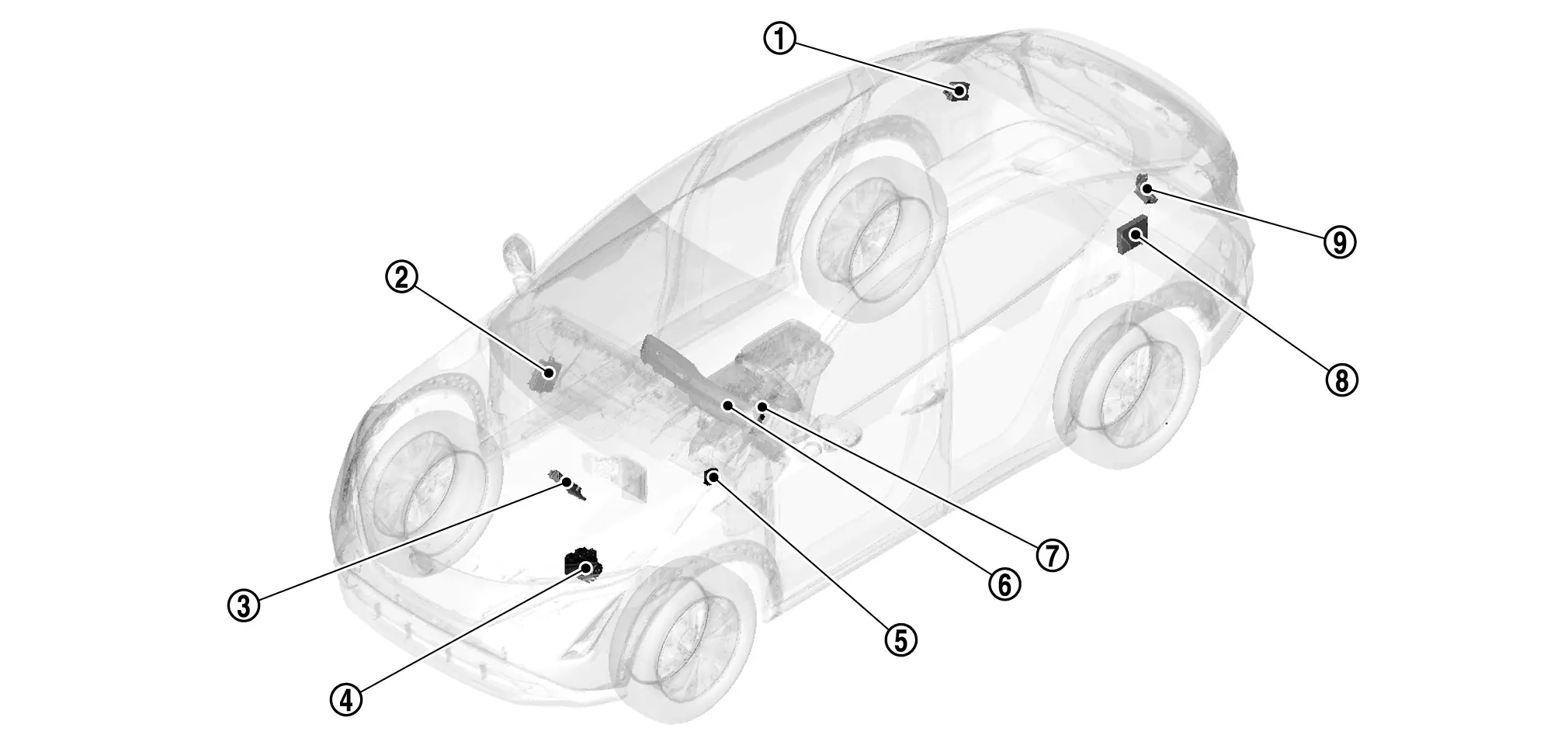
ADAS control unit 2

Refer to Component Parts Location for detailed installation location.

BCM

Refer to Component Parts Location for detailed installation location.

VCM

Refer to Component Parts Location or detailed installation location.

ABS actuator and electric unit (control unit)

Refer to Component Parts Location for detailed installation location.

Chassis control module

Refer to Component Parts Location for detailed installation location.

Combination meter

Refer to Component Parts Location for detailed installation location.

Steering angle sensor

Refer to Component Parts Location for detailed installation location.

Around view monitor control unit

Refer to Component Parts Location for detailed installation location.

Sonar control unit

Refer to Component Parts Location for detailed installation location.

System Nissan Ariya 2023

System Description

SYSTEM DIAGRAM
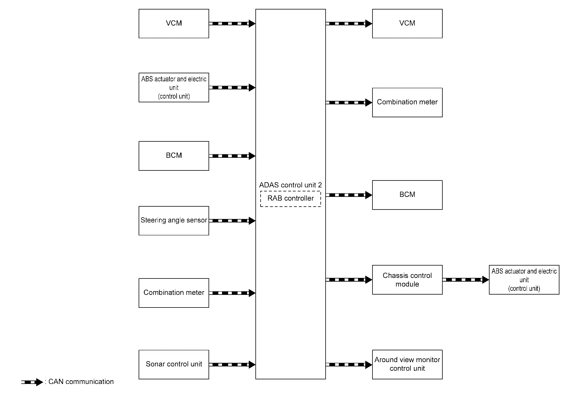
ComponentFunction
VCM Component Description
ABS actuator and electric unit (control unit) Component Description
Chassis control module Component Description
BCM System Description
Steering angle sensor Component Description
Combination meter Combination Meter
Sonar control unit Sonar Control Unit
Around view monitor control unit Around View Monitor Control Unit
ADAS control unit 2 ADAS Control Unit 2

ADAS CONTROL UNIT 2 INPUT/OUTPUT SIGNAL ITEM

Input Signal Item

Transmit unitSignal nameDescription
VCM CAN communication READY status signal Receives READY status
Accelerator pedal position signal Receives accelerator pedal position (angle)
ABS actuator and electric unit (control unit) CAN communication ABS malfunction signal Receives a malfunction state of ABS
TCS malfunction signal Receives a malfunction state of TCS
VDC malfunction signal Receives a malfunction state of VDC
Nissan Ariya Vehicle speed signal (ABS) Receives wheel speeds of four wheels
Brake fluid pressure signal Receives brake fluid pressure
BCM CAN communication Stop lamp switch signal Receives an operational state of the brake pedal
Steering angle sensor CAN communication Steering angle sensor signal Receives the number of revolutions, turning direction of the steering wheel
Combination meter CAN communication System selection signal Receives a selection state of each item selected with the combination meter
Sonar control unit CAN communication Sonar sensor signal Receives obstacle information (existence & distance)

Output Signal Item

Reception unitSignal nameDescription
VCM CAN communication Torque down request signal Transmits a signal to control the motor torque
Combination meter CAN communication Meter display signal Transmits a signal to display a state of the system on the information display
Buzzer output signal Transmits a signal to activate buzzer
RAB warning lamp signal
  • Transmits a signal to illuminate RAB warning lamp

  • Transmits an ON/OFF state of the RAB

BCM CAN communication Stop lamp request signal Transmits a signal to activates the stop lamp
ABS actuator and electric unit (control unit) (via chassis control module) CAN communication Brake fluid pressure control signal Transmits a brake fluid pressure control signal to activates the brake
Around view monitor control unit CAN communication RAB warning signal Transmits a RAB warning signal to appear the red frame in the center display

FUNCTION DESCRIPTION

  • The Rear Automatic Braking system can assist the driver when the vehicle is backing up and approaching objects directly behind the Nissan Ariya vehicle.
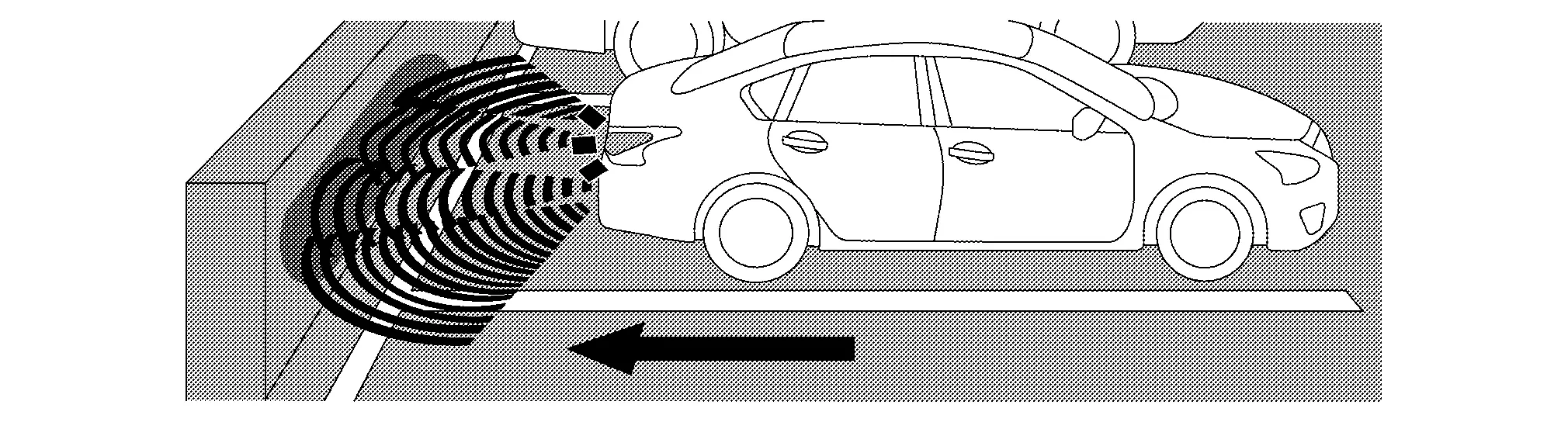
  • When the shift lever is in the R (Reverse) position and the Nissan Ariya vehicle speed is less than approximately 3 and 15 km/h, the RAB system operates.

  • The RAB system detects obstacles behind the Nissan Ariya vehicle using the sonar sensors.

  • If a risk of a collision with an obstacle is detected when own Nissan Ariya vehicle is backing up, the RAB system warning indicator blinks in the vehicle information display, a red frame appears in the center display (with Intelligent Around View Monitor system), and the system chimes three times.

  • The system automatically applies the brakes.

OPERATION DESCRIPTION

  • Sonar detects a object approaching, and transmits the object detection signal to ADAS control unit 2 via CAN communication.

  • The ADAS control unit 2 performs the following operations according to the degree of possibility of a collision.

    • Transmits the buzzer output signal to the combination meter and sounds the buzzer.

    • Transmits the meter display signal to the combination meter and displays the RAB system warning indicator.

    • Transmits the brake fluid pressure control signal to the ABS actuator and electric unit (control unit) and performs the brake control.

    • Transmits the stop lamp request signal to BCM and turn ON the stop lamp.

OPERATION CONDITION

ADAS control unit 2 performs the control when the following conditions are satisfied.

  • RAB system: ON

  • Vehicle speed: Between approximately 3 and 15 km/h

  • When there is a possibility of a collision with the object backward.

CANCEL CONDITION

The ADAS control unit 2 cancels the operation when the system is under any conditions of the operation cancellation condition.

  • When the system judges that the vehicle comes to a standstill by the system control.

  • When the system malfunction occurs.

  • When the sonar area of the rear bumper is dirty and the measurement of the distance between the object becomes difficult.

Fail-safe (ADAS Control Unit 2)

Refer to Fail-safe (ADAS Control Unit 2).

Warning Lamp/Indicator Lamp

NameDesignFunction
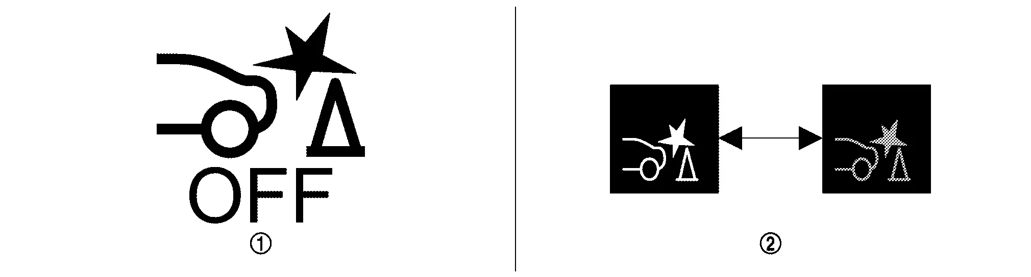
RAB warning lamp
  • The RAB warning lamp warns the driver that RAB system is OFF.

  • The RAB warning lamp warns the driver of a malfunction in the RAB system.

  • For layout, Refer to Design.

Operation Nissan Ariya

Operation

SWITCH NAME AND FUNCTION
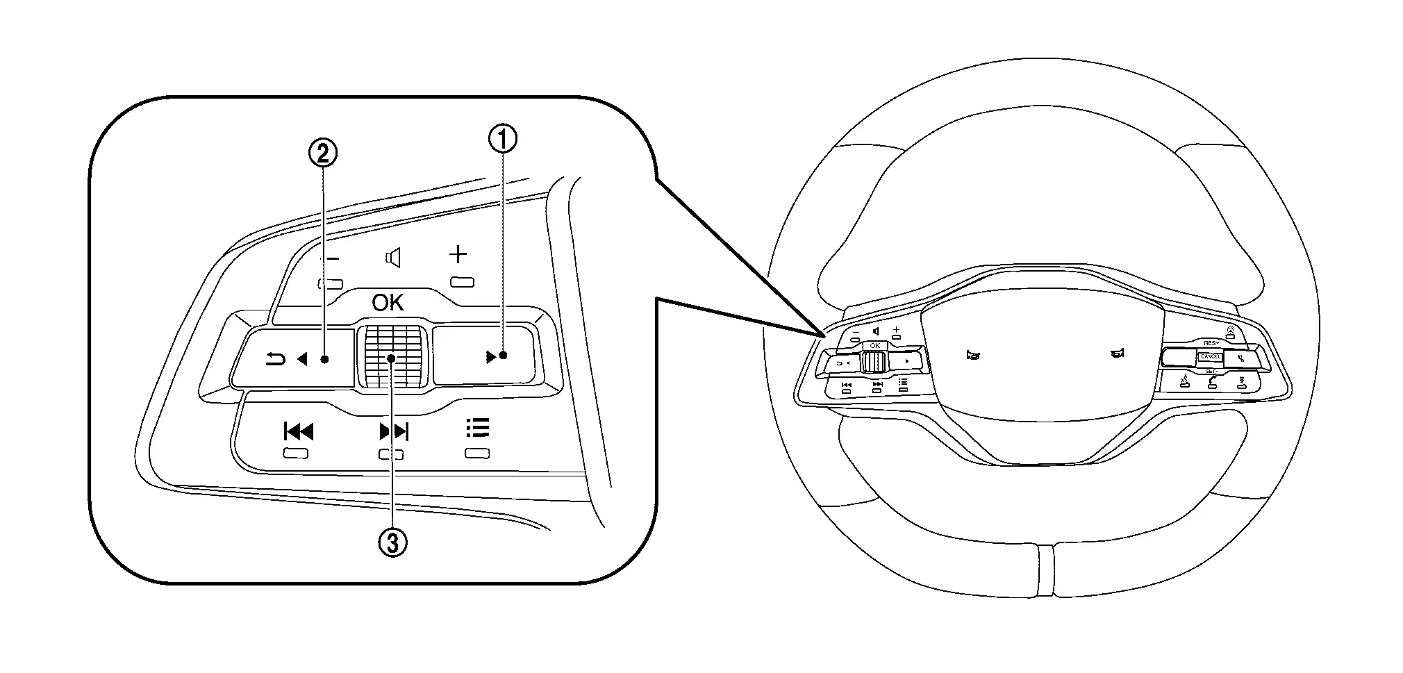
No.Switch nameDescription
RIGHT SW
  1. Using the steering switch, select the [Settings] menu in the information display

  2. Select the [Driver Assistance] menu

  3. Select the [Emergency Brake] menu

  4. Select the [Rear] item to turn the system ON/OFF

LEFT/BACK SW
OK SW/Jog dial

SYSTEM DISPLAY

No.Switch nameDescription
RAB warning lamp
  • RAB warning lamp indicates that an malfunction condition is present in RAB system

  • When the RAB system turns OFF, the RAB warning lamp will illuminate.

RAB indicator Blinks when there is a possibility of a collision with the object backward

DISPLAY AND WARNING

System Display

ConditionActionDisplay on information displayWarning lampBuzzer
RAB OFF — — ON OFF
RAB ON There is not a possibility of a collision with the object backward — — OFF OFF
There is a possibility of a collision with the object backward Operates brake

White⇔Red

OFF Beep
RAB system malfunction The RAB system is automatically canceled*

Malfunction

See Owner’s Manual
ON Beep
When RAB system cannot be operated temporily The RAB system is automatically canceled* — Blink OFF