Removal and Installation
- Instrument Panel Assembly
- Center Console Assembly
- Console Slide Switch
Instrument Panel Assembly Nissan Ariya: FE0
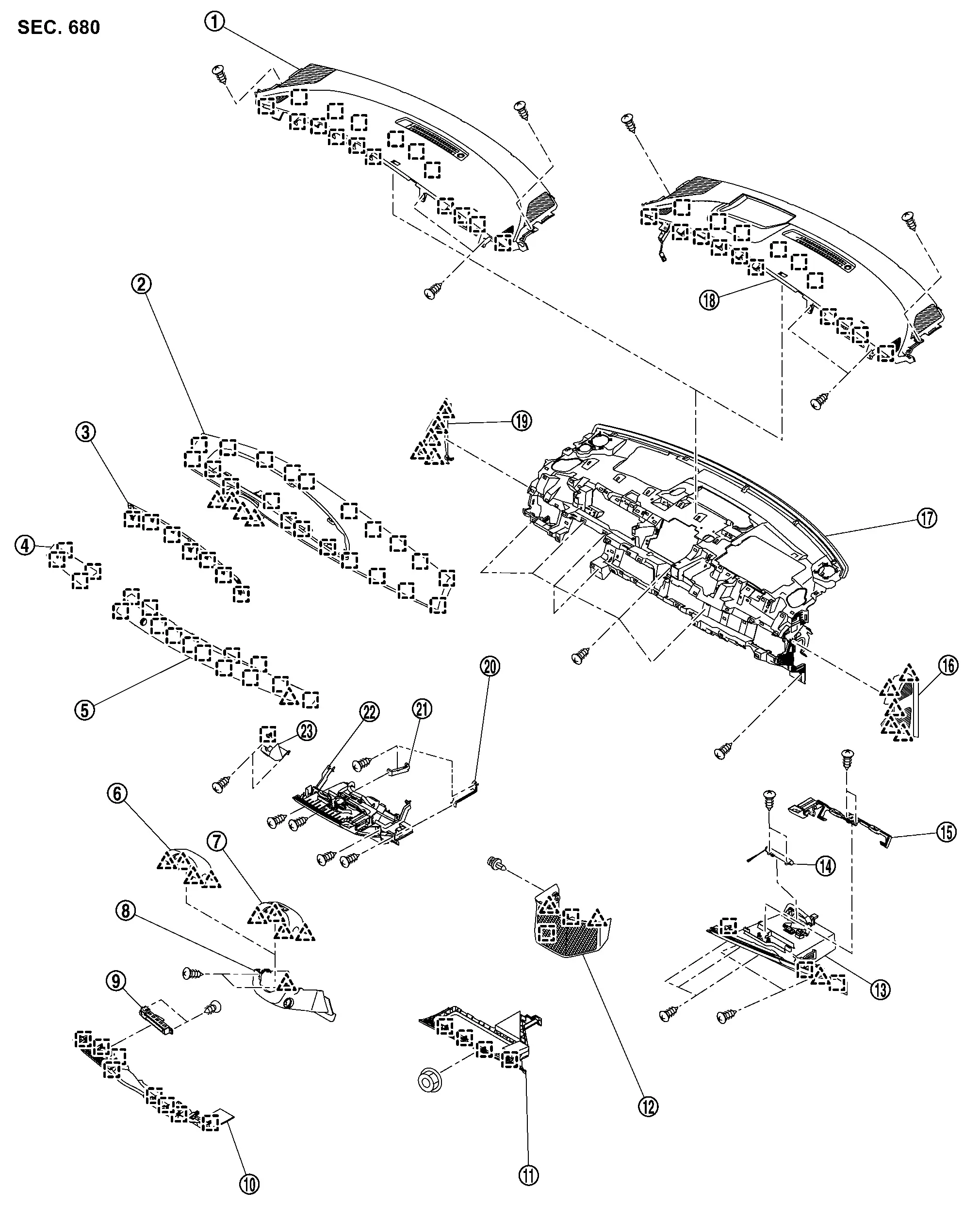
Exploded View
 |
Instrument upper garnish (without head up display) |  |
Instrument pad B |  |
Meter cover |
 |
Instrument finisher A |  |
Instrument finisher B |  |
Steering column cover upper (without driver monitor camera) |
 |
Steering column cover upper (with driver monitor camera) |  |
Steering column cover lower |  |
Switch bracket |
 |
Instrument lower panel |  |
Instrument lower cover |  |
Instrument lower cover center |
 |
Glove box assembly |  |
Glove box damper |  |
Glove box lock |
 |
Instrument mask LH |  |
Instrument panel assembly |  |
Instrument upper garnish (with head up display) |
 |
Instrument mask RH |  |
Bracket RH |  |
Bracket LH |
 |
Center box / Flexible center storage |  |
Electrical parking brake switch | ||
 |
: Pawl | ||||
 |
: Metal clip | ||||
Removal & Installation
WORK STEP
When removing instrument panel assembly, integrated interface display and AV control unit take steps in the order shown by the numbers below.
| PARTS | INSTRUMENT PANEL ASSEMBLY | AV CNTROL UNIT | INTEGRATED INTERFACE DISPLAY |
|---|---|---|---|
| Front kicking plate LH / RH | [1] | ||
| Body side welt | [2] | ||
| Dash side finisher LH / RH | [3] | ||
| Instrument mask RH (RHD models is LH) | [4] | ||
| Instrument lower cover | [5] | ||
| Glove box assembly | [6] | ||
| Passenger knee air bag module | [7] | ||
| Instrument mask LH | [8] | ||
| Instrument lower panel | [9] | ||
| Driver knee air bag module | [10] | ||
| Instrument lower cover center | [11] | ||
| Instrument finisher B | [12] | ||
| Instrument finisher A | [13] | ||
| Electrical parking brake switch bracket | [14] | ||
| Center box / Flexible center storage | [15] | ||
| Steering wheel | [16] | ||
| Meter cover | [17] | [1] | [1] |
| Integrated interface display | [18] | [2] | [2] |
| Instrument pad B | [19] | [3] | |
| Sunload sensor | [20] | [4] | |
| Front pillar garnish LH / RH | [21] | [5] | |
| Passenger air bag module harness connector | [22] | [6] | |
| Passenger air bag module mounting bolt | [23] | [7] | |
| Instrument upper garnish | [24] | [8] | |
| Center ventilator grill | [25] | ||
| Side ventilator grill | [26] | ||
| AV control unit | [27] | [9] | |
| Intelligent key unit | [28] | ||
| Meter speaker | [29] | ||
| Front squawker | [30] | ||
| Steering column cover | [31] | ||
| Spiral cable | [32] | ||
| Combination switch | [33] | ||
| Instrument panel assembly | [34] |
[]: Number indicates step in removal procedure.
REMOVAL
Remove front kicking plate LH/RH. Refer to Removal & Installation.
Remove body side welt of instrument panel section. Refer to Removal & Installation.
Remove dash side finisher. Refer to Removal & Installation.
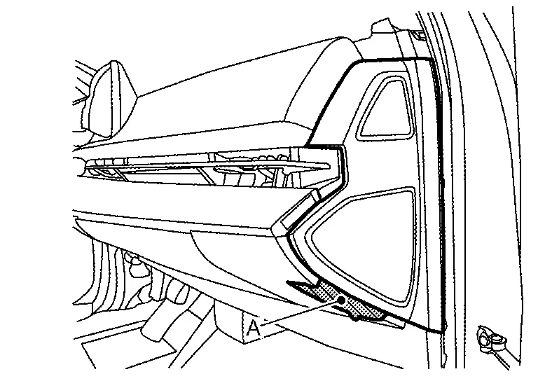
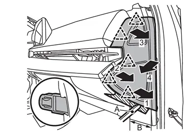
Remove instrument mask RH.Apply protective tape (A) on the part to protect it from damage.
|
: Pawl |
| B | : 90 mm (3.54 in) |
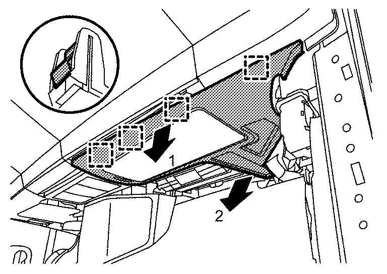
Remove instrument lower cover.Remove instrument lower cover fixing trim nut. Disengage fixing metal clips according to numerical order 1→2 indicated by arrows as shown in the figure, and then remove instrument lower cover.
|
: Metal clip |
Remove glove box assembly.Remove glove box assembly fixing screws  .
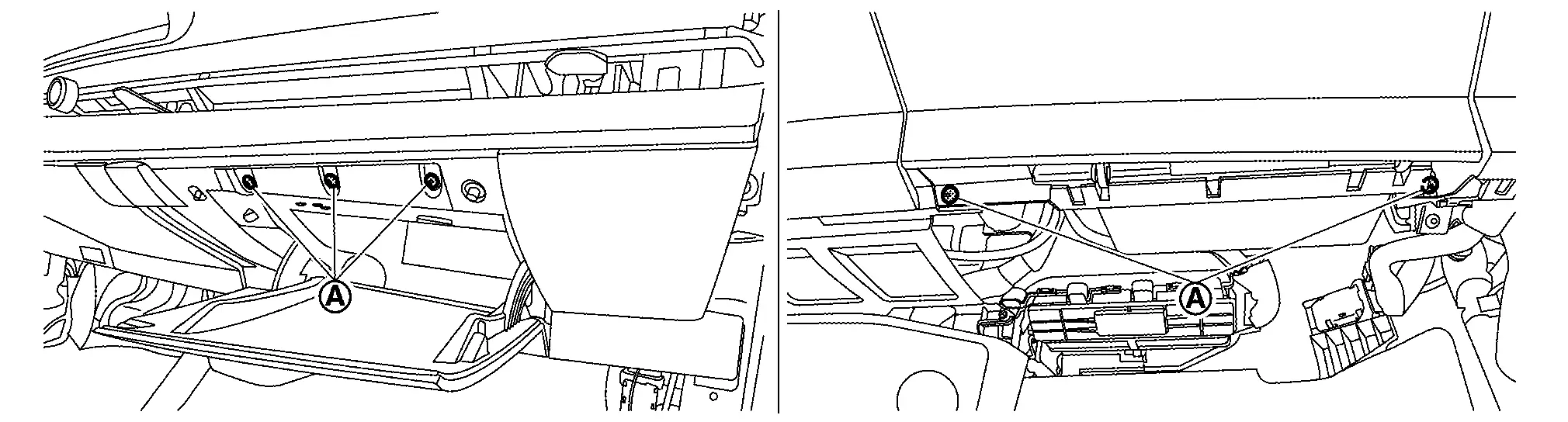

|
: Pawl |
|
: Metal clip |
Remove passenger knee air bag module. Refer to Removal & Installation.
Remove instrument mask LH.Apply protective tape (A) on the part to protect it from damage.
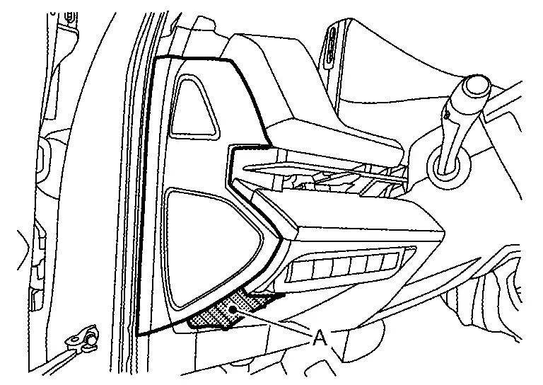

|
: Pawl |
| B | : 90 mm (3.54 in) |
Remove instrument lower panel.Disengage fixing metal clips according to numerical order 1→4 indicated by arrows as shown in figure.

|
: Metal clip |
Remove driver knee air bag module. Refer to Removal and Installation.
Remove instrument lower cover center.Remove fixing clip .
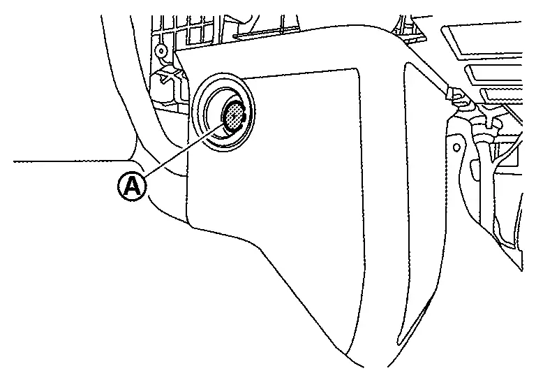
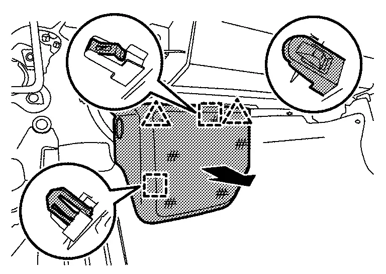
|
: Pawl |
|
: Metal clip |
Remove instrument finisher B.Disengage fixing pawl and metal clips according to numerical order 1→2 indicated by arrows as shown in figure.
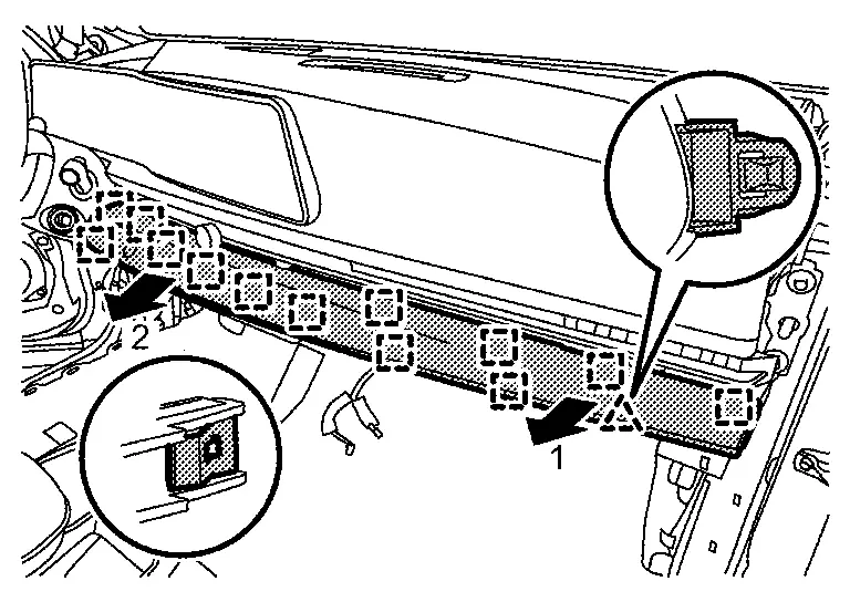
|
: Pawl |
|
: Metal clip |
Disengage fixing metal clips, and them remove instrument finisher A.
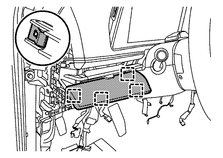
|
: Metal clip |
Remove electric parking brake switch.Remove electric parking brake switch fixing screws .
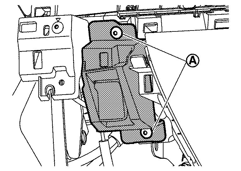
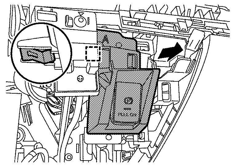
|
: Metal clip |
Remove center box / flexible center storage.Disconnect harness connector , and then disengage body harness fixing clip  (flexible center storage).
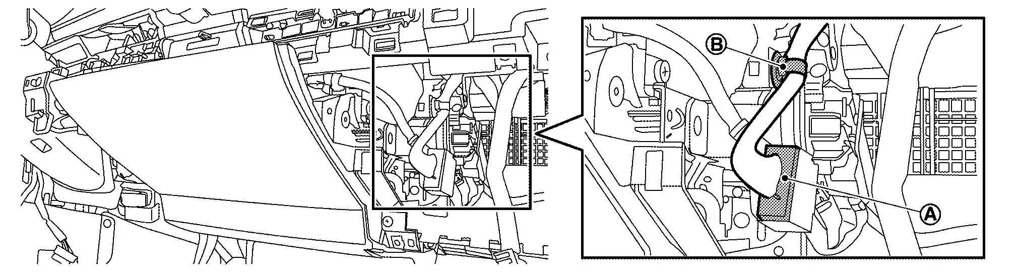 .
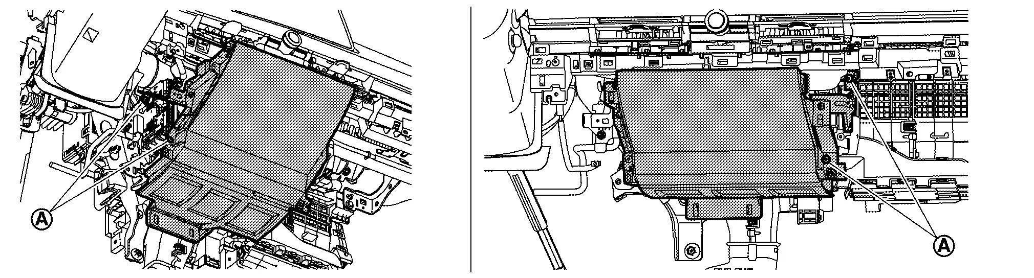
Remove steering wheel. Refer to STEERING WHEEL : Removal & Installation.
Disengage fixing metal clips according to numerical order 1→3 indicated by arrows as shown in figure using a remover tool (A), and then remove meter cover.
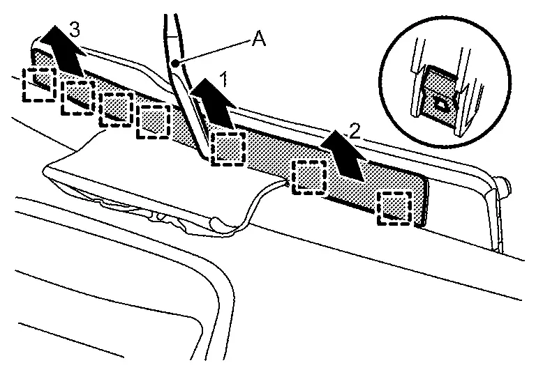
|
: Metal clip | ||||
Remove integrated interface display. Refer to Removal and Installation.
Remove instrument pad B.Pull up the skirt part of instrument pad B to disengage fixing pawls, and then remove it from steering column cover upper.
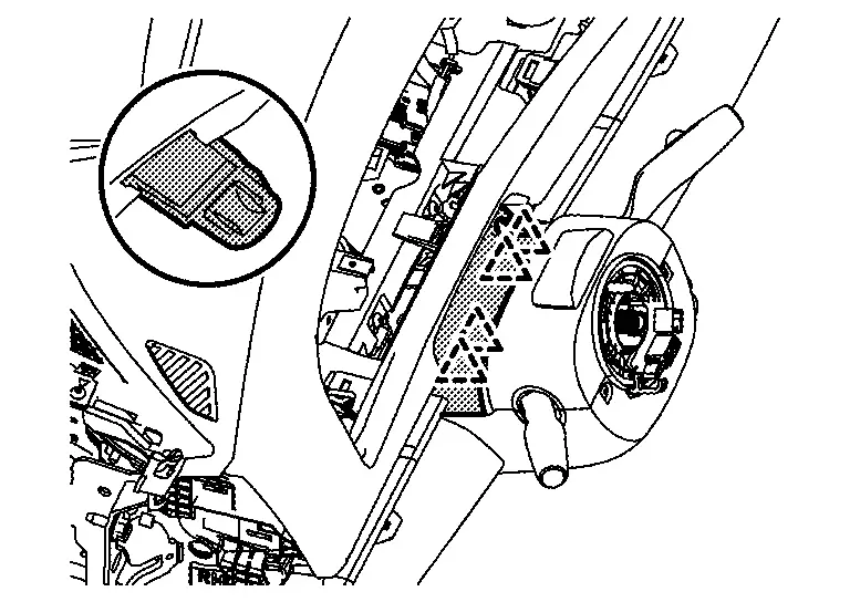
|
: Pawl |
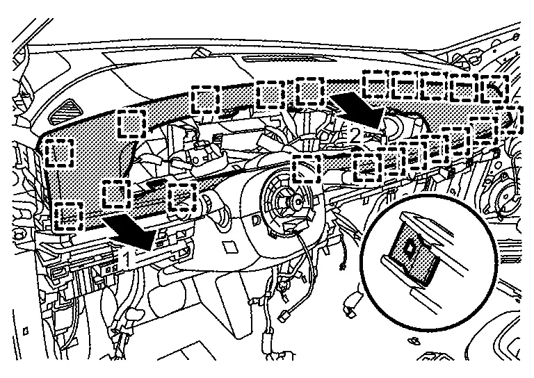
|
: Metal clip | ||||
Remove sunload sensor. Refer to Removal & Installation.
Remove front pillar garnish. Refer to Removal & Installation.
Remove passenger air bag module harness connector.
Remove passenger air bag module mounting bolt .

Remove instrument upper garnish.Remove fixing screws .
Upper side
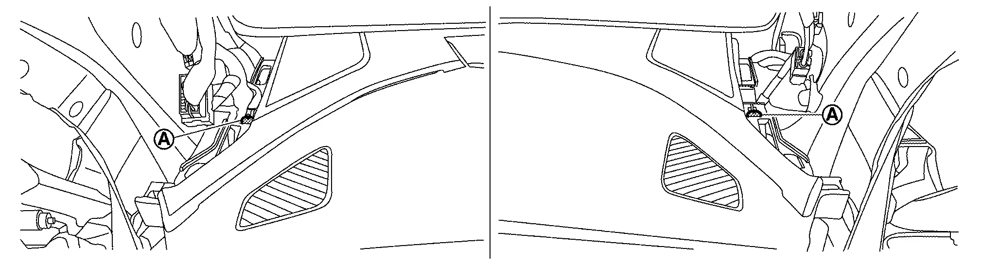
Passenger seat side

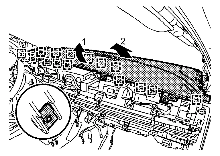
|
: Metal clip |
Remove center ventilator grill. Refer to Removal & Installation.
Remove side ventilator grill. Refer to Removal & Installation.
Remove AV control unit. Refer to Removal & Installation.
Remove intelligent key unit. Refer to Removal and Installation.
Remove meter speaker. Refer to Removal and Installation.
Remove front squawker. Refer to Removal & Installation.
Remove steering column cover.Remove steering column cover fixing screws .
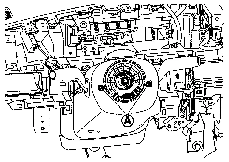
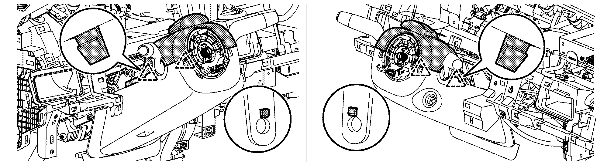
|
: Pawl |
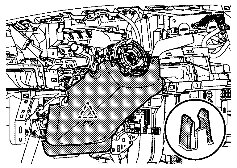
|
: Pawl |
Remove spiral cable. Refer to Removal & Installation.
Remove combination switch. Refer to Removal and Installation.
Remove instrument panel assembly.Remove instrument panel assembly fixing screws .
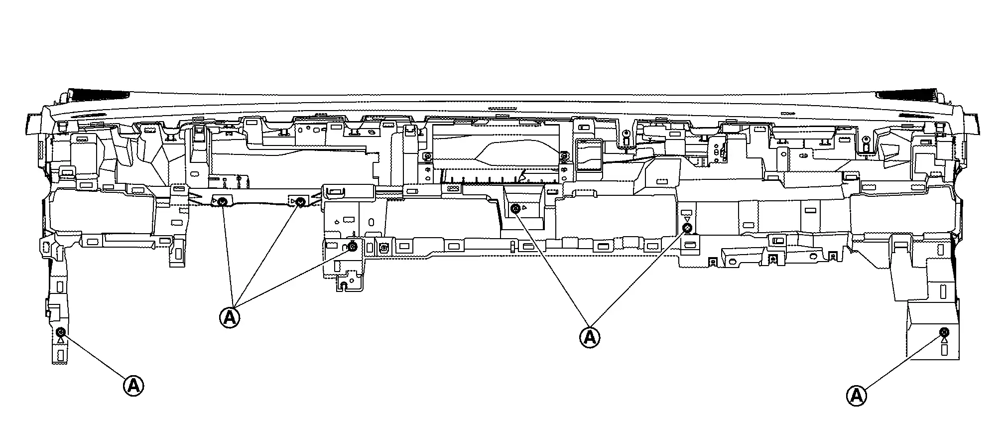
Remove the following parts after removing instrument panel assembly.
Front defroster nozzle : Removal & Installation.
Side defroster nozzle : Removal & Installation
GPS antenna : Removal & Installation
Telematics antenna (with telematics system) : Refer to Removal & Installation.
Warning buzzer : Removal & Installation
INSTALLATION
Note the following items, and then install in the reverse order of removal.
Confirm that the parts are assembled for sure.
Center Console Assembly Nissan Ariya 1st generation
Exploded View

|
Console lid | |
Center console finisher | |
Center console harness |
|
Console cover LH | |
Slide plate*1 | |
Center console finisher rear upper |
|
Center console finisher rear lower | |
Console rear cap LH | |
Console cover rear |
|
Console rear cap RH | |
Slide plate rail*1 | |
Console cover RH |
|
Console body lower | |
Console cover front | |
Knee pad assembly |
|
Console slide switch | |
Console slide switch bezel | |
Electric shift selector |
|
Console tray mat | |
Console tray rubber | |
Console tray |
|
Console body upper | |
Switch bracket*2 |  |
Rear seat heater switch RH*3 |
 |
USB power socket*4 |  |
Rear seat heater switch LH*3 | ||
|
: Pawl | ||||
 |
: N·m (kg-m, in-lb) | ||||
*1 : With center console slide
*2 : With switch / USB power socket
*3 : With USB power socket
Removal & Installation
REMOVAL
Slide the driver and passenger seat to rearmost position.
Remove console cover front.Disengage console cover front fixing pawls.

|
: Pawl |
Remove center console assembly mounting bolts of front side.
Slide the driver and passenger seat to frontmost position.
Disengage fixing pawls using a remover tool (A), and then remove console rear cap LH / RH.
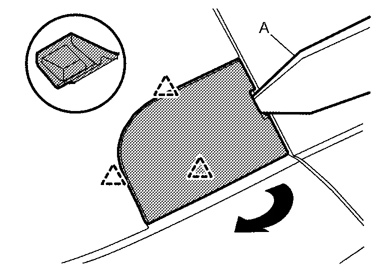
|
: Pawl |
Remove center console assembly mounting bolts of rear side, and then remove center console assembly.
INSTALLATION
Note the following item, and then install in the reverse order of removal.
Disassembly & Assembly
DISASSEMBLY
Remove console tray mat and console tray rubber.
Remove center console finisher.Disengage fixing pawls according to numerical order 1→2 indicated by arrows as shown in figure.
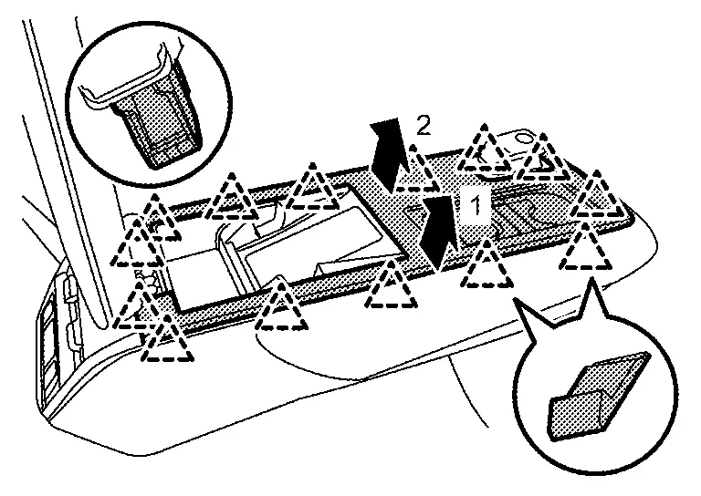
|
: Pawl |
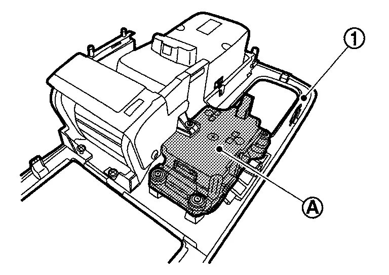
Remove console slide switch (with console slide). Refer to Removal & Installation.
Remove console tray.Remove fixing screw .
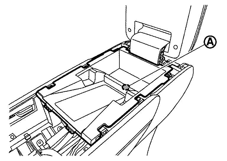

|
: Pawl |
Remove center console finisher rear upper.Disengage fixing pawls using a remover tool (A) according to numerical order 1→3 indicated by arrows as shown in figure.
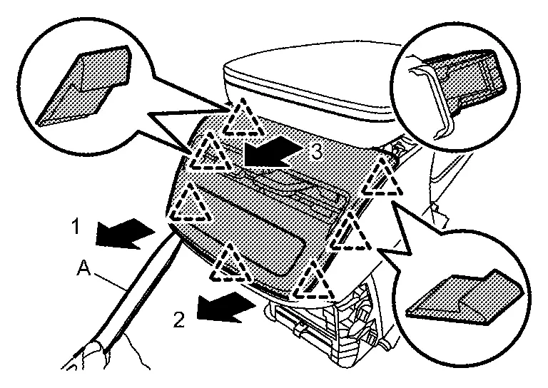
|
: Pawl |
Rear seat heater switch (with rear seat heater switch) : Removal and Installation.
USB charge socket (with USB charge socket) : CENTER CONSOLE USB POWER SOCKET : Removal & Installation.
Rear ventilator grill : Removal & Installation.
, and then remove switch bracket. 
Remove console lid.Remove fixing screws .
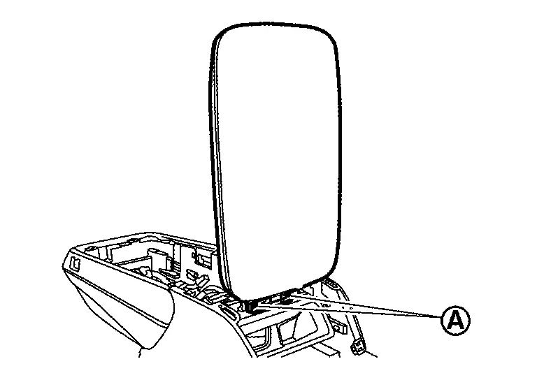
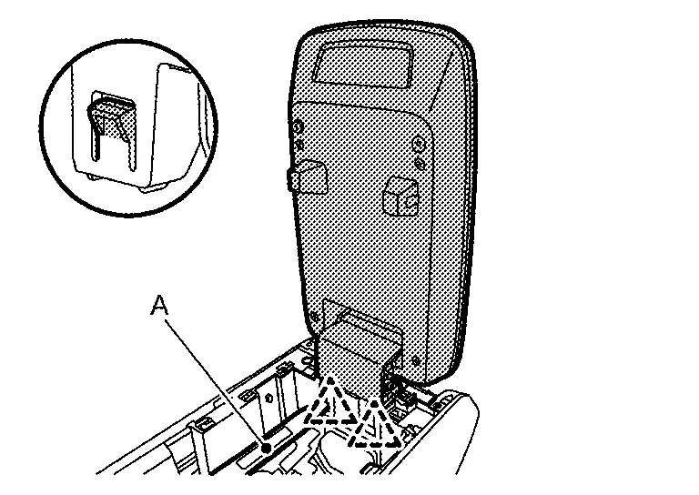
|
: Pawl |
Disengage fixing pawls using a remover tool (A) according to numerical order 1→2 indicated by arrows as shown in figure, and then remove center console finisher rear lower.

|
: Pawl |
Remove rear console duct. Refer to Removal & Installation.
Remove knee pad assembly.Remove fixing screws .
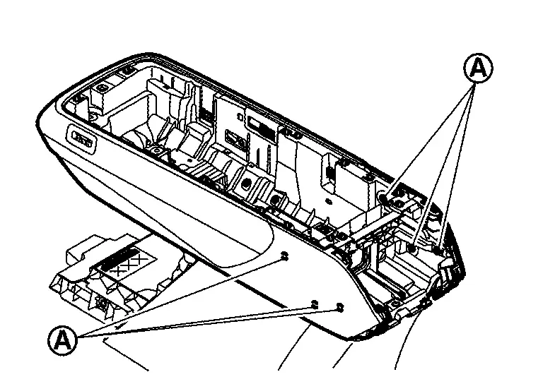

|
: Pawl |
Remove center console assembly from Nissan Ariya vehicle. Refer to Removal & Installation.
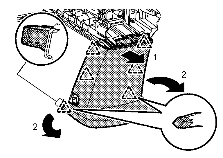
Remove console cover rear.Remove fixing screw , and then remove slide plate according arrow direction as shown in figure (with console slide).
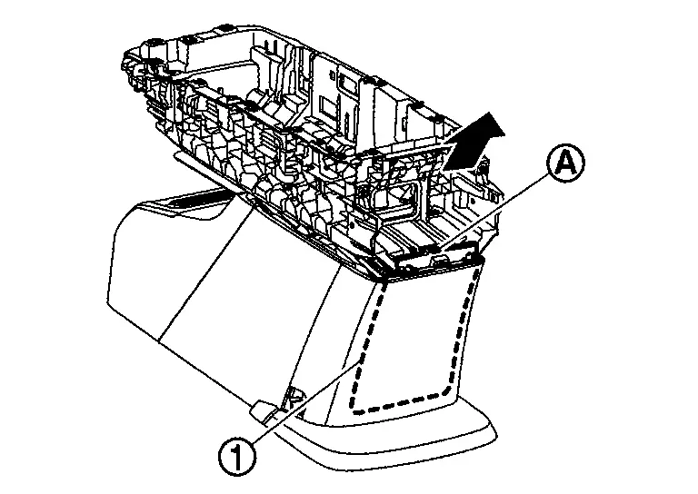
|
: Pawl |
, and then remove slide plate rail from console cover rear. 
|
: Pawl |
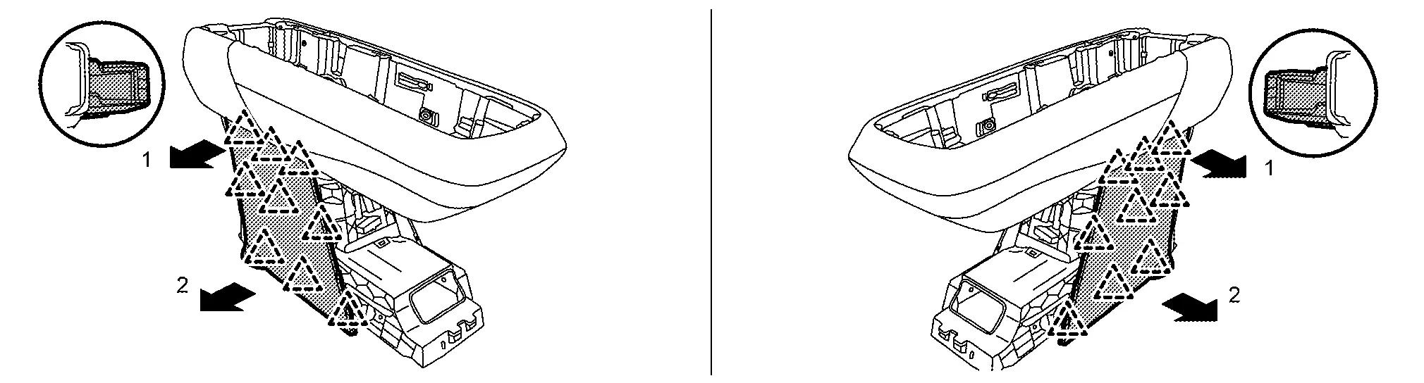
Disengage fixing pawls according to numerical order 1→2 indicated by arrows as shown in figure, and then remove console cover LH and RH.
|
: Pawl |
Remove console body upper.Disconnect console slide motor harness connector .

Remove following parts from console body lower.
Center console harness.
Electrical shift control unit : ELECTRIC SHIFT SELECTOR : Removal & Installation.
ASSEMBLY
Assemble in the reverse order of disassembly.
Console Slide Switch Nissan Ariya first Gen
Exploded View
For exploded View, refer to Exploded View.
Removal & Installation
REMOVAL
Remove center console finisher. Refer to Disassembly & Assembly.
Disengage console slide switch fixing pawls using a remover tool (A).

|
: Pawl |
Remove harness connector, and then remove console slide switch and bezel as a set.
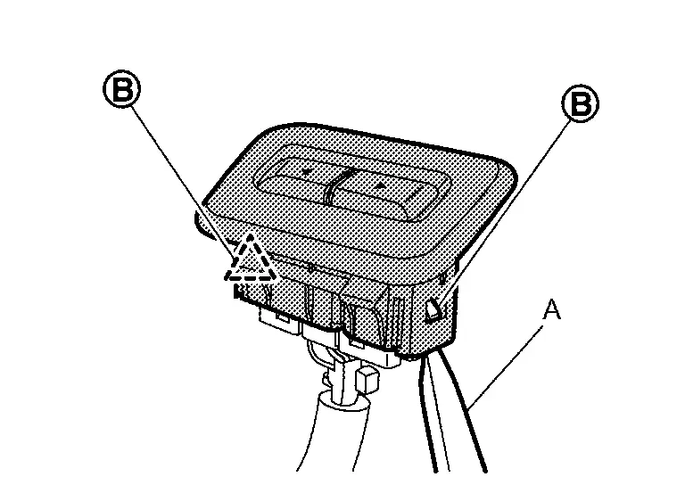
Disengage fixing pawls using a remover tool (A), and then remove console slide switch from bezel.
|
: Pawl |
INSTALLATION
Install in the reverse order of removal.