System Description

In this manual: System Description
How to Use This Manual — 1Precautions — 1Preparation — 1Vehicle Information — 1Basic Inspection — 1Preparation. Commercial Service Tools Or/and Repair Part — 1Description — 1Component Parts — 1System — 1Diagnosis System (vcm) — 1Ecu Diagnosis Information. Vcm — 1Ev Control System — 1Ev/hev (vcm) — 1Component Parts /circuit Diagnosis — 1Ev Control System — 1Periodic Maintenance. Ev System Warning Lamp — 1Removal and Installation. Vcm — 1Traction Motor System :: Front Traction Motor — 1Preparation — 1Description — 4Basic Inspection — 2Dtc Diagnosis — 2Component Parts /circuit Diagnosis — 1Traction Motor System :: Rear Traction Motor — 1Description — 4Basic Inspection — 2Dtc Diagnosis — 2Component Parts /circuit Diagnosis — 1Removal and Installation — 1Ev Battery System :: 66kwh Li-Ion Battery — 1Description — 4Basic Inspection — 2Dtc Diagnosis — 2Component Parts /circuit Diagnosis — 1Removal and Installation — 1Disassembly and Assembly — 2Service Data — 1Ev Battery System :: 91kwh Li-Ion Battery — 1Description — 4Basic Inspection — 2Dtc Diagnosis — 2Component Parts /circuit Diagnosis — 1Removal and Installation — 1Disassembly and Assembly — 1Service Data — 2Preparation. Vehicle Charging System — 1Vehicle Charging System :: Description — 1Component Parts — 2System — 1Diagnosis System (on-Board Charger) — 1Diagnosis System (dc/dc Converter) — 1Ecu Diagnosis Information — 1Vehicle Charging System — 1Charger/pd Module (on-Board Charger) — 1Cplc (cplc) — 1Dcdc (dc/dc Converter) — 1Component Parts/circuit Diagnosis — 1Symptom Diagnosis — 1Evse Inspection — 1Periodic Maintenance — 1Removal and Installation — 1Disassembly and Assembly — 1Preparation. High Voltage Cooling System — 1Description — 1Symptom Diagnosis. Overheating Cause Analysis — 1Periodic Maintenance — 1Coolant — 1Removal and Installation — 1Radiator — 1Service Data — 1Removal and Installation. Accelerator Control System — 1Reduction Gear: Re1f62a — 1Removal and Installation — 1Transaxle & Transmission :: Electric Shift — 1Description — 3Basic Inspection — 2Dtc Diagnosis — 2Component Parts /circuit Diagnosis — 1Removal and Installation — 1Rear Final Drive: Rn1r62a — 1Removal and Installation — 1Preparation. Front Axle System — 1Symptom Diagnosis. Noise, Vibration and Harshness (nvh) Troubleshooting — 1Periodic Maintenance — 1Removal and Installation — 1Service Data. Front Drive Shaft — 12wd — 14wd — 1Periodic Maintenance — 1Removal and Installation — 1Preparation. Front Suspension System — 1Symptom Diagnosis. Noise, Vibration and Harshness (nvh) Troubleshooting — 1Periodic Maintenance — 1Removal and Installation — 1Service Data — 1Symptom Diagnosis. Noise, Vibration and Harshness (nvh) Troubleshooting — 1Periodic Maintenance — 1Removal and Installation — 1Service Data — 1Preparation. Road Wheels & Tires System — 1Description — 1System — 1Ecu Diagnosis Information. Bcm (body Control Module) — 1Tpms — 1Dtc/circuit Diagnosis — 1Symptom Diagnosis — 1Periodic Maintenance. Road Wheels & Tires — 1Removal and Installation — 1Service Data — 1Preparation. Brake System — 1System Description — 1Component Parts — 1Ecu Diagnosis Information. Electrically-Driven Intelligent Brake Unit — 1Basic Inspection — 1Dtc/circuit Diagnosis — 1Symptom Diagnosis — 1Periodic Maintenance — 1Removal and Installation — 1Service Data — 1Preparation. Parking Brake System — 1System Description — 1Component Parts — 1System — 1Ecu Diagnosis Information. Abs Actuator and Electric Unit (control Unit) — 1Basic Inspection. Diagnosis and Repair Work Flow — 1Component Parts /circuit Diagnosis — 1Symptom Diagnosis — 1Removal and Installation — 1Brake Control System :: With Vdc — 1System Description — 3Basic Inspection — 2Dtc/circuit Diagnosis — 1Symptom Diagnosis — 2Removal and Installation — 1Brake Control System :: Automatic Brake Hold — 1System Description — 3Component Parts /circuit Diagnosis — 1Removal and Installation — 1Brake Control System :: E-Step — 1System Description — 3Removal and Installation — 1System Description — 1Ecu Diagnosis Information — 1Basic Inspection — 1Symptom Diagnosis — 1Rear Automatic Braking — 1System Description — 1Basic Inspection — 1Preparation. Steering System — 1System Description — 1Component Parts — 1Basic Inspection — 1Dtc/circuit Diagnosis — 1Symptom Diagnosis — 1Periodic Maintenance. Steering Wheel — 1Removal and Installation — 1Service Data — 1System Description — 1Component Parts — 1Steering Control System — 1Ecu Diagnosis Information. Power Steering Control Module — 1Dtc/circuit Diagnosis — 1Component Parts /circuit Diagnosis — 1Symptom Diagnosis — 1Removal and Installation. Power Steering Control Module — 1System Description — 1Removal and Installation — 1System Description — 1System — 1Basic Inspection. Diagnosis and Repair Work Flow — 1Dtc/circuit Diagnosis — 1Symptom Diagnosis — 1Component Parts — 1Basic Inspection — 1Removal and Installation — 1System Description — 1System — 1Ecu Diagnosis Information. Air Bag Diagnosis Sensor Unit — 1Basic Inspection — 1Dtc/circuit Diagnosis — 1Symptom Diagnosis — 1System Description. Description. Ventilation System — 1Removal and Installation — 1Preparation. Preparation — 1System Description — 1Basic Inspection — 1Symptom Diagnosis — 1Removal and Installation — 1Electric Compressor — 1Cooler Pipe and Hose — 1A/c Unit Assembly Cover — 1A/c Unit Assembly — 1Heater & Air Conditioning Control System :: Automatic Air Conditioning — 1System Description — 1Ecu Diagnosis Information — 1Basic Inspection — 2Dtc Diagnosis — 1Symptom Diagnosis — 1Removal and Installation — 2Preparation. Preparation — 1Symptom Diagnosis. Squeak and Rattle Trouble Diagnoses — 1Removal and Installation — 1Preparation. Instrument Panel — 1Component Parts — 1System — 1Ecu Diagnosis Information. Flexible Center Storage Control Module — 1Basic Inspection. Diagnosis and Repair Work Flow — 1Dtc/circuit Diagnosis — 1Symptom Diagnosis — 1Removal and Installation — 1Preparation. Preparation — 1Component Parts — 1System — 1Ecu Diagnosis Information. Driver Lumbar Support Control Module — 1Basic Inspection. Diagnosis and Repair Work Flow — 1Dtc/circuit Diagnosis — 1Symptom Diagnosis — 1Removal and Installation — 1System Description — 1System — 1Ecu Diagnosis Information — 1Basic Inspection — 1Dtc/circuit Diagnosis — 1Symptom Diagnosis — 1Manual Function Does Not Operate — 1Memory Function Does Not Operate — 1Removal and Installation — 1Preparation. Preparation — 1System Description — 1System (intelligent Key System) — 1Diagnosis System (bcm) — 1Ecu Diagnosis Information — 1Basic Inspection — 1Dtc/circuit Diagnosis — 1U2141-87 Can Comm Circuit — 1Power Supply and Ground Circuit — 1Symptom Diagnosis — 1Automatic Back Door Operation Does Not Operate — 1Back Door Does Not Open — 1Door Does Not Lock/unlock with Door Lock and Unlock Switch — 1Removal and Installation — 1Hood — 1Radiator Core Support — 1Charge Port Lid — 1Front Fender — 1Front Door — 1Rear Door — 1Back Door — 1Hood Lock — 1Front Door Lock — 1Rear Door Lock — 1Back Door Lock — 1Outside Key Antenna — 1System Description — 1System — 1Ecu Diagnosis Information. Inverter (front), Inverter (rear), Bcm, Intelligent Key Unit — 1Basic Inspection — 1Dtc/circuit Diagnosis — 1Symptom Diagnosis — 1Preparation — 1Symptom Diagnosis. Squeak and Rattle Trouble Diagnoses — 1Removal and Installation — 1System Description — 1Ecu Diagnosis Information — 1Basic Inspection — 1Dtc/circuit Diagnosis — 1Power Supply and Ground Circuit — 1Symptom Diagnosis — 1Front Passenger Side Power Window Does Not Operate — 1Rear Lh Side Power Window Does Not Operate — 1Rear Rh Side Power Window Does Not Operate — 1Removal and Installation. Power Window Main Switch — 1Preparation. Preparation — 1System Description — 1Ecu Diagnosis Information — 1Basic Inspection — 1Dtc/circuit Diagnosis — 1Power Supply and Ground Circuit — 1Sunroof Switch Assembly — 1Symptom Diagnosis — 1Auto Operation Does Not Operate — 1Removal and Installation — 1Preparation — 1Description — 1Symptom Diagnosis. Squeak and Rattle Trouble Diagnoses — 1Removal and Installation — 1Service Information — 6Repair Information — 1Precaution — 1Preparation — 1Removal and Installation — 1Service Data — 1Preparation. Preparation — 1Component Parts — 1System — 1Ecu Diagnosis Information — 1Wiring Diagram. Door Mirror — 1Basic Inspection. Diagnosis and Repair Work Flow — 1Dtc/circuit Diagnosis — 1Power Supply and Ground Circuit — 1Symptom Diagnosis — 1Removal and Installation — 1Exterior Lighting System :: Led Headlamp — 1System Description — 3Basic Inspection — 1Dtc/circuit Diagnosis — 1Symptom Diagnosis — 1Periodic Maintenance — 1Removal and Installation — 1System Description — 1System — 1Diagnosis System (bcm) — 1Ecu Diagnosis Information. Bcm, Intelligent Key Unit — 1Basic Inspection. Diagnosis and Repair Work Flow — 1Dtc/circuit Diagnosis — 1Symptom Diagnosis. Interior Lighting System Symptom — 1Removal and Installation — 1Service Data. Bulb Specifications — 1System Description — 1System — 1Ecu Diagnosis Information. Bcm, Ipdm E/r — 1Basic Inspection. Diagnosis and Repair Work Flow — 1Dtc/circuit Diagnosis — 1Symptom Diagnosis — 1Removal and Installation — 1System Description — 1Ecu Diagnosis Information. Bcm — 1Basic Inspection. Diagnosis and Repair Work Flow — 1Dtc/circuit Diagnosis — 1Symptom Diagnosis — 1Removal and Installation — 1Preparation. Preparation — 1Removal and Installation. Horn — 1Preparation. Commercial Service Tools Or/and Repair Part — 1System Description — 1Component Parts — 1Ecu Diagnosis Information. Approaching Vehicle Sound for Pedestrians (vsp) Control Unit — 1Approaching Vehicle Sound for Pedestrians (vsp) — 1Vsp [approaching Vehicle Sound for Pedestrians (vsp) Control Unit] — 1Approaching Vehicle Sound for Pedestrians (vsp) System — 1Removal and Installation — 1Removal and Installation — 1Wireless Charger — 1System Description — 1Basic Inspection — 1Dtc/circuit Diagnosis — 1Removal and Installation — 1Component Parts — 1System — 1Diagnosis System (bcm) — 1Ecu Diagnosis Information. Bcm — 1Basic Inspection — 1Dtc/circuit Diagnosis — 1Symptom Diagnosis — 1Removal and Installation — 1Can Fundamental — 1Description — 1Trouble Diagnosis — 1Can (controller Area Network) — 1Description — 1
~9min read
  • Component Parts
  • System

Component Parts Nissan Ariya 2023

Component Parts Location

Rear power window motor RH Rear power window switch RH Front door lock assembly (passenger side) (door switch)
Front power window motor (passenger side) Front power window switch (passenger side)

BCM

Refer to Component Parts Location.
Power window main switch Front door lock assembly (driver side) (door switch) Rear power window switch LH
Front power window motor (driver side) Rear power window motor LH
View with front door finisher removed View with rear door finisher removed

Power Window Main Switch

COMPONENT FUNCTION WITHIN SYSTEM
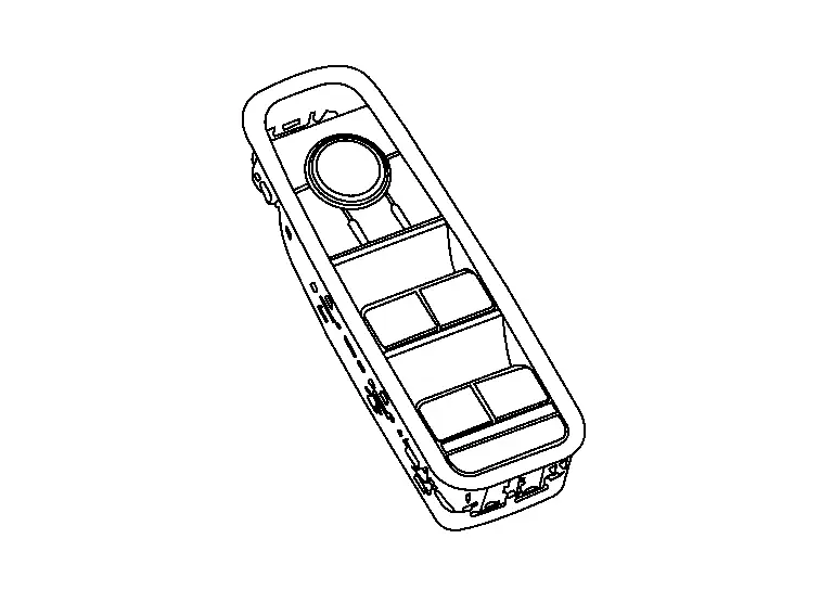
  • Power window main switch controls all power window motors.

  • Power window lock switch inhibits power window operation by rear power window switch.

INDIVIDUAL COMPONENT FUNCTION

  • Transmits signal to each power window motor.

  • Turns ON/OFF the power window lock switch.

COMPONENT OPERATION

  • When power window main switch is operated, it transmits signal to each power window motor via LIN communication.

  • When power window main switch (passenger side switch, rear LH/RH switch) is operated, it transmits signal to each power window motor via LIN communication.

  • DOWN circuit between the power window main switch and the front power window motor (driver side) enables the DOWN operation even when LIN communication of the power window main switch cannot be performed due to the Nissan Ariya vehicle submersion.
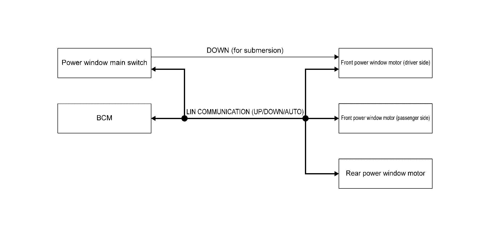
COMPONENT PARTS LOCATION

Power window main switch is installed to front door finisher (driver side). Refer to Component Parts Location.

Front Power Window Switch (Passenger side)

COMPONENT FUNCTION WITHIN SYSTEM
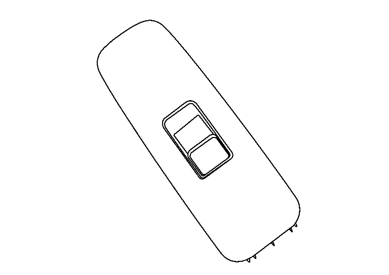
Front power window switch (passenger side) controls front power window motor (passenger side).

INDIVIDUAL COMPONENT FUNCTION

Transmits signal to front power window motor (passenger side).

COMPONENT OPERATION

When front power window switch (passenger side) is operated, it transmits signal to front power window motor (passenger side).
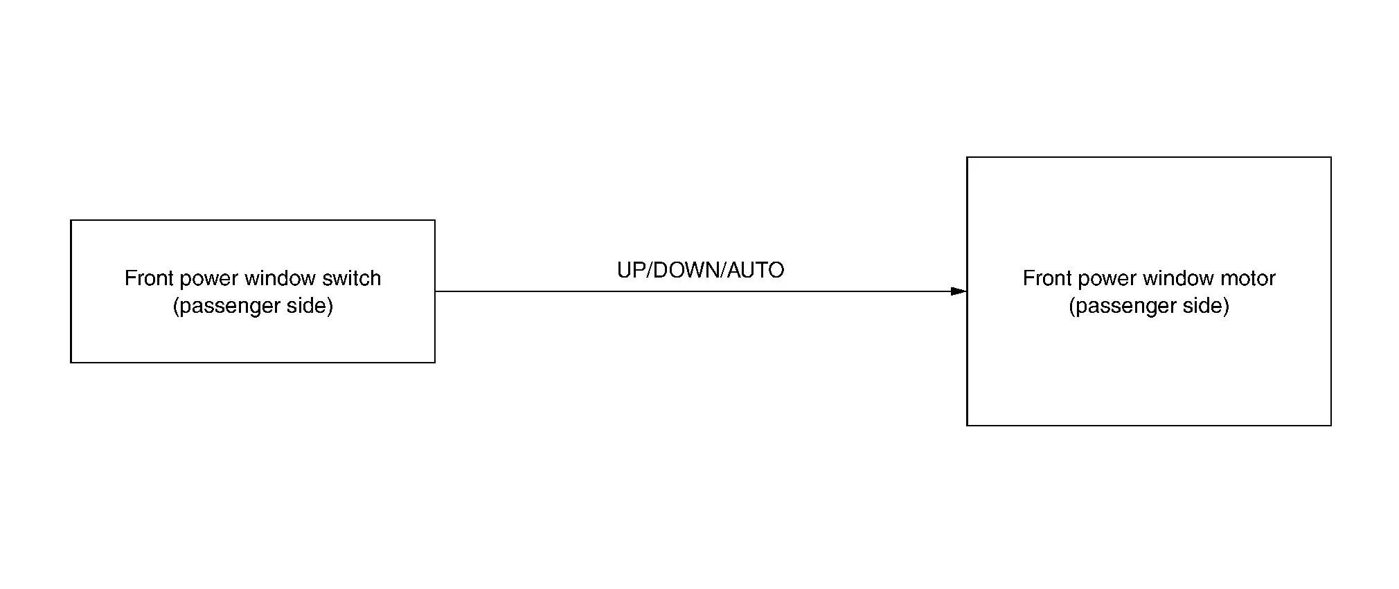
COMPONENT PARTS LOCATION

Front power window switch (passenger side) is installed to front door finisher (passenger side). Refer to Component Parts Location.

Rear Power Window Switch

COMPONENT FUNCTION WITHIN SYSTEM
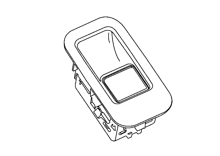
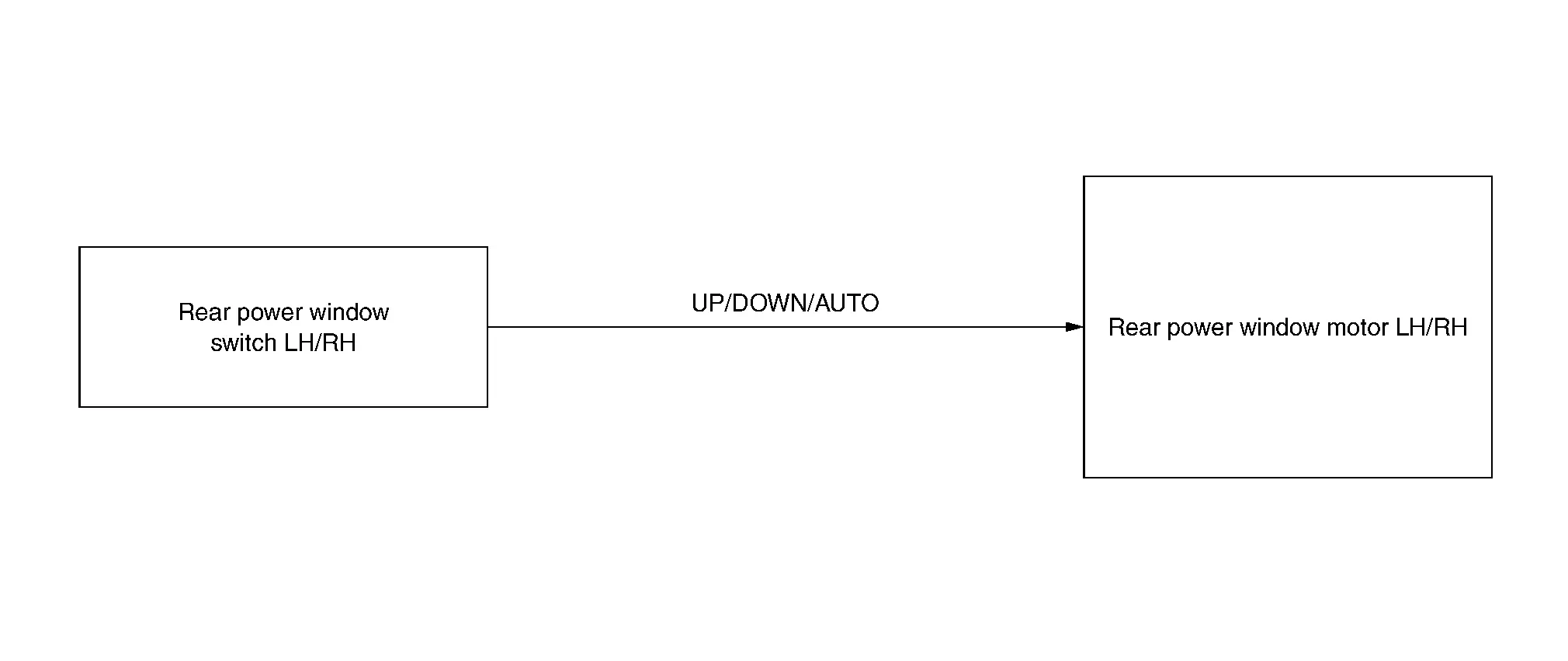
Rear power window switch LH/RH controls each rear power window motor.

INDIVIDUAL COMPONENT FUNCTION

Transmits signal to each rear power window motor.

COMPONENT OPERATION

When rear power window switch LH/RH is operated, it transmits signal to each rear power window motor.
COMPONENT PARTS LOCATION

Rear power window switch is installed to rear door finisher. Refer to Component Parts Location.

Front Power Window Motor (Driver Side)

COMPONENT FUNCTION WITHIN SYSTEM
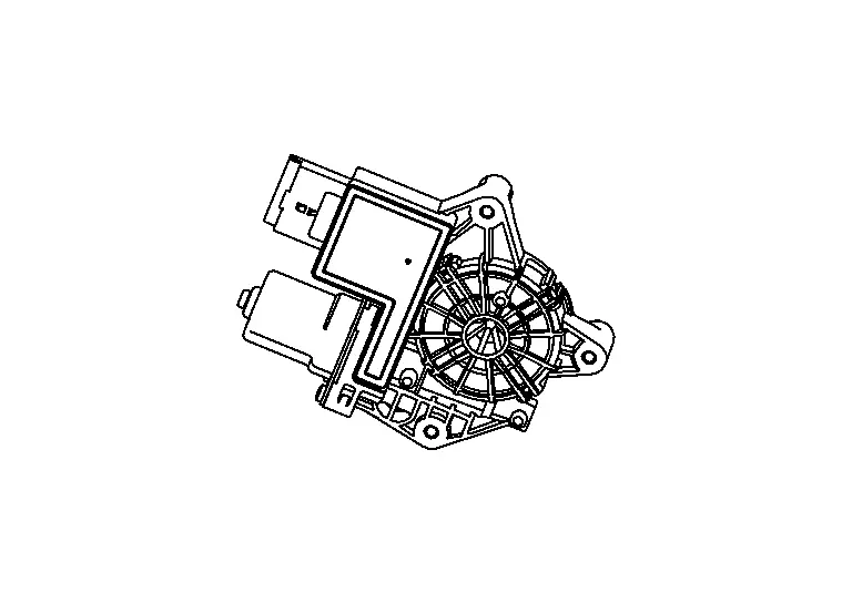
  • Power window motor controls door glass.

  • Power window motor controls AUTO operation.

  • Power window motor controls anti-pinch function.

INDIVIDUAL COMPONENT FUNCTION

Opens/closes door glass.

COMPONENT OPERATION

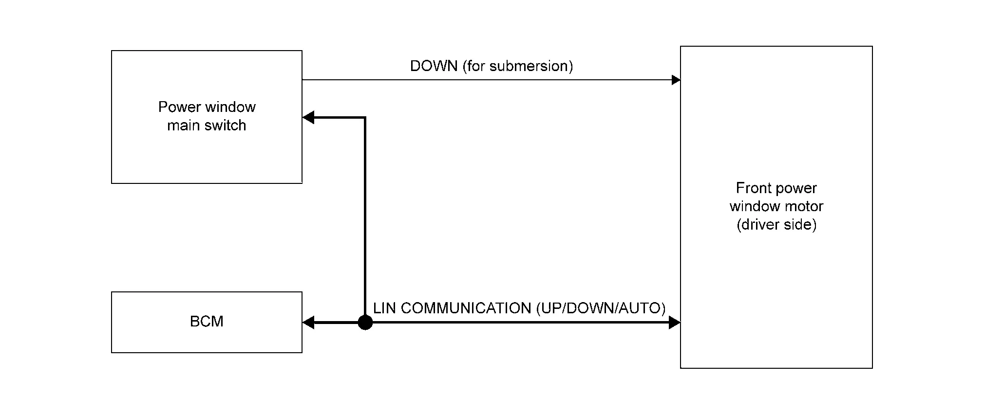
  • Front power window motor (driver side) receives signal from power window main switch and BCM via LIN communication, then opens/closes door glass.

  • DOWN circuit between the power window main switch and the front power window motor (driver side) enables the DOWN operation even when LIN communication of the power window main switch cannot be performed due to the Nissan Ariya vehicle submersion.
COMPONENT PARTS LOCATION

Front power window motor (driver side) is installed to front door regulator (driver side). Refer to Component Parts Location.

Front Power Window Motor (Passenger Side)

COMPONENT FUNCTION WITHIN SYSTEM

  • Power window motor controls door glass.

  • Power window motor controls AUTO operation.

  • Power window motor controls anti-pinch function.

INDIVIDUAL COMPONENT FUNCTION

Opens/closes door glass.

COMPONENT OPERATION

Front power window motor (passenger side) receives signal from front power window switch (passenger side), and from power window main switch and BCM via LIN communication, then opens/ closes door glass.
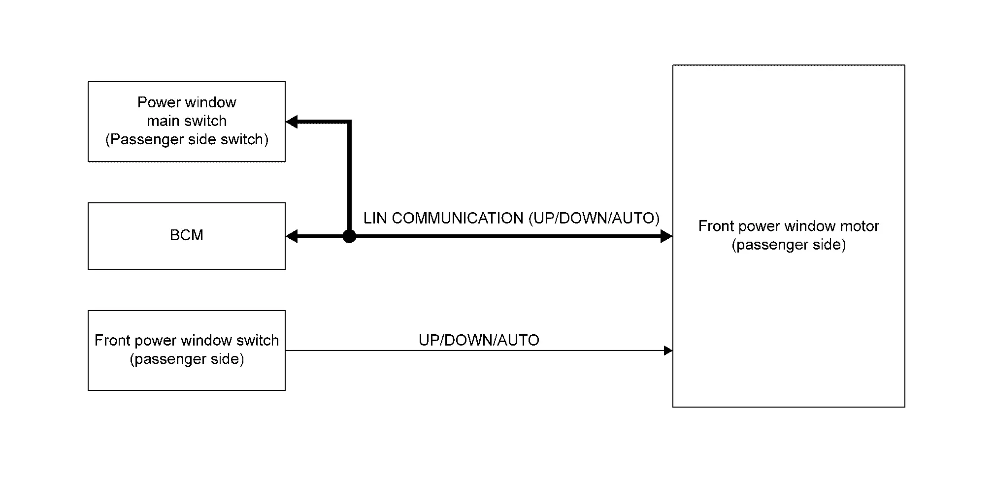
COMPONENT PARTS LOCATION

Front power window motor (passenger side) is installed to front door regulator (passenger side). Refer to Component Parts Location.

Rear Power Window Motor

COMPONENT FUNCTION WITHIN SYSTEM

  • Power window motor controls door glass.

  • Power window motor controls AUTO operation.

  • Power window motor controls anti-pinch function.

INDIVIDUAL COMPONENT FUNCTION

Opens/closes door glass.

COMPONENT OPERATION

Rear power window motor LH/RH receives signal from rear power window switch LH/RH, and from power window main switch and BCM via LIN communication, then opens/closes door glass.
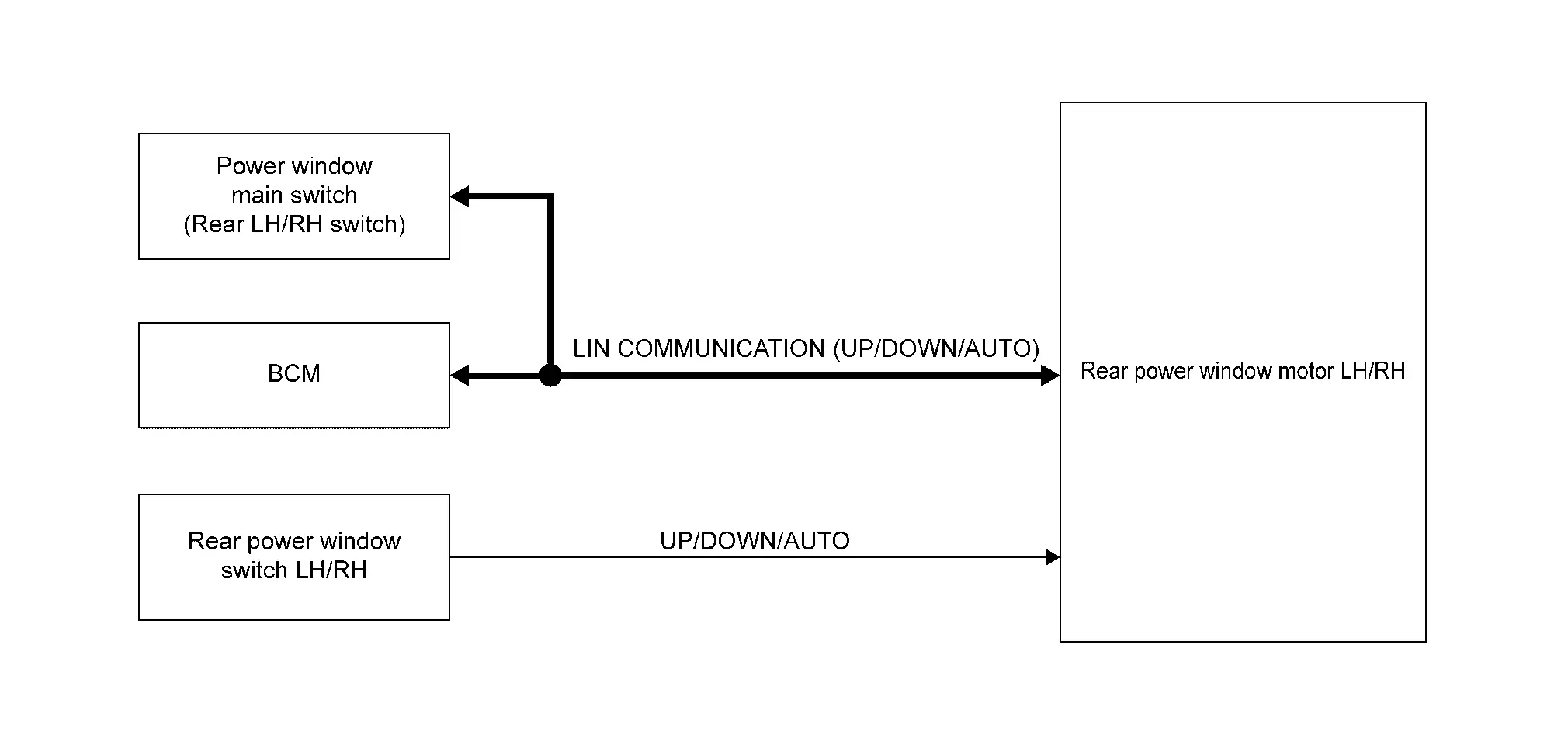
COMPONENT PARTS LOCATION

Rear power window motor LH/RH is installed to rear door regulator LH/RH. Refer to Component Parts Location.

System Nissan Ariya 2026

System Description

SYSTEM DIAGRAM
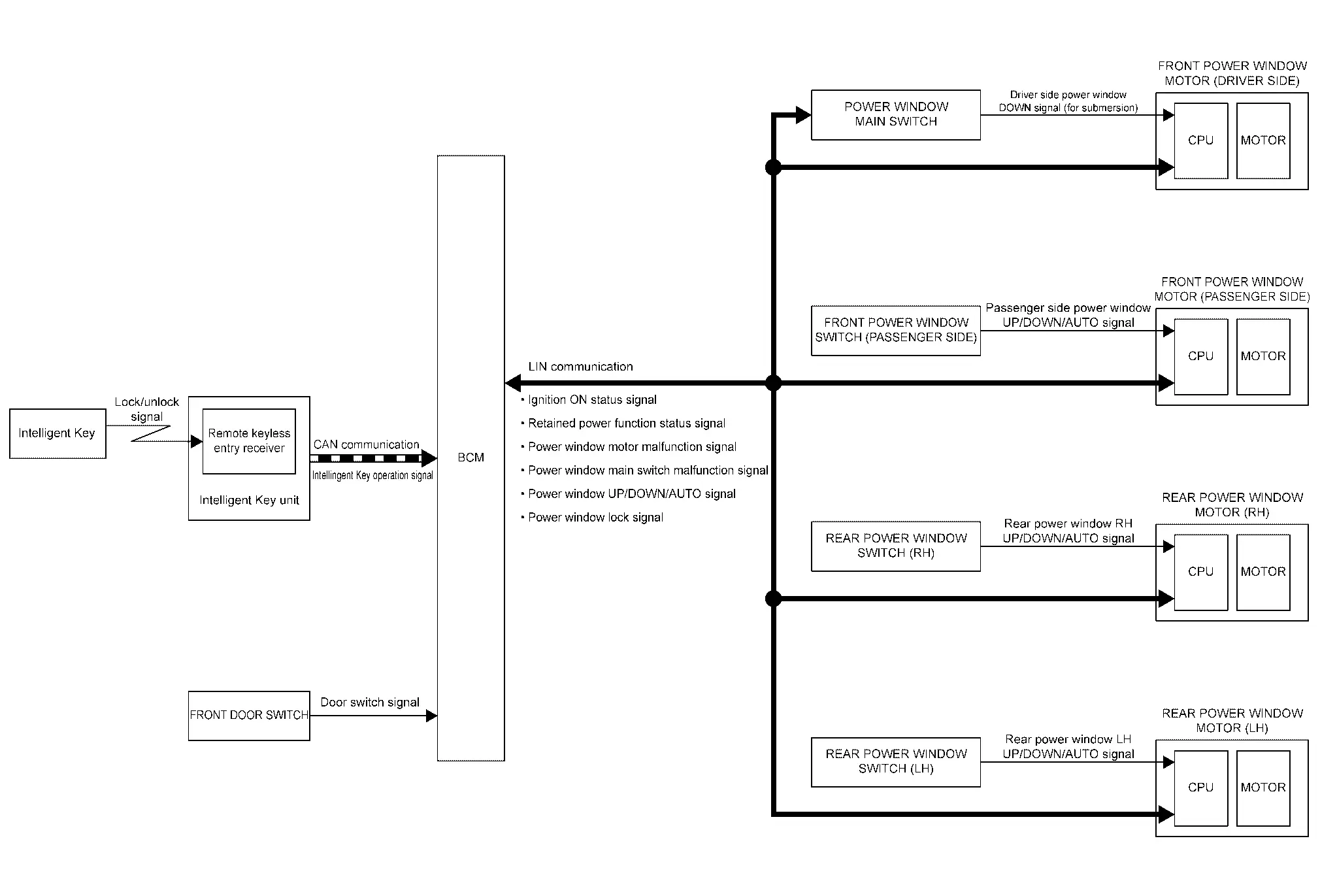
Component partsFunction
Front door switch Detects front door open/close condition and transmits door switch signal to BCM.
BCM
  • Controls retained power function.

  • Controls remote control function.

  • Transmits the power switch ON signal, retained power function status signal, power window UP/DOWN/AUTO signal and power window lock signal to front power window motor via LIN communication.

Power window main switch Refer to Power Window Main Switch.
Front power window switch (passenger side) Refer to Front Power Window Switch (Passenger side).
Rear power window switch LH Refer to Rear Power Window Switch.
Rear power window switch RH Refer to Rear Power Window Switch.
Front power window motor (driver side) Refer to Front Power Window Motor (Driver Side).
Front power window motor (passenger side) Refer to Front Power Window Motor (Passenger Side).
Rear power window motor LH Refer to Rear Power Window Motor.
Rear power window motor RH Refer to Rear Power Window Motor.
Intelligent Key unit Detects Intelligent Key is operated, Intelligent Key operation signal to BCM via CAN communication.
Intelligent Key Transmits Intelligent Key operation signal to Intelligent Key unit.

POWER WINDOW OPERATION

  • Power window system is activated by power window switch when power switch turns ON or retained power is operating.

  • Power window main switch opens/closes all door glass.

  • Front and rear power window switch opens/closes the corresponding door glass.

  • All power window motor, power window main switch and BCM transmit and receive signal by LIN communication.

POWER WINDOW AUTO-OPERATION

  • AUTO UP/DOWN operation can be performed when each power window switch turns to AUTO.

  • Each power window switch transmits AUTO UP/DOWN signal to each power window motor and operating the each power window motor turns to AUTO.

  • Each power window motor reads the changes of operating condition and stops AUTO operation when door glass is at fully opened/closed position.

RETAINED POWER FUNCTION

Retained power function is an additional power supply function that enables power window system to operate for 45 seconds after power switch turns OFF.

RETAINED POWER FUNCTION CANCEL CONDITIONS

Any of the following condition is satisfied.

  • Front door CLOSE → OPEN.

  • When power switch turns ON again.

  • When timer times out. (45 seconds)

POWER WINDOW LOCK

Power window main switch transmits power window lock signal to rear power window motor LH/RH via LIN communication, and disable the rear LH/RH power window switch operation.

ANTI-PINCH SYSTEM

  • Pinch foreign material in the door glass during MANUAL/AUTO UP operation, and it is the anti-pinch function that lowers the door glass when detected.

  • CPU continues detecting the movement of each power window motor while each power window motor is operating.

  • Each power window motor controls to lower the door glass for approximately 145 mm (5.71 in) or more after it detects foreign material is trapped in the door glass.

OPERATION CONDITION

  • When door glass MANUAL/AUTO UP operation is performed (anti-pinch function does not operate just before the door glass closes and is fully closed)

REMOTE CONTROL FUNCTION

  • All power windows open when the unlock button on Intelligent Key is activated and kept pressed for more than for approximately 3 seconds with the power switch OFF.

OPERATION CONDITION

  • Power switch OFF.

  • Power window motor initialized condition.

  • When the unlock button is released.

  • When the power switch is switched ON while the power window opening is operated.

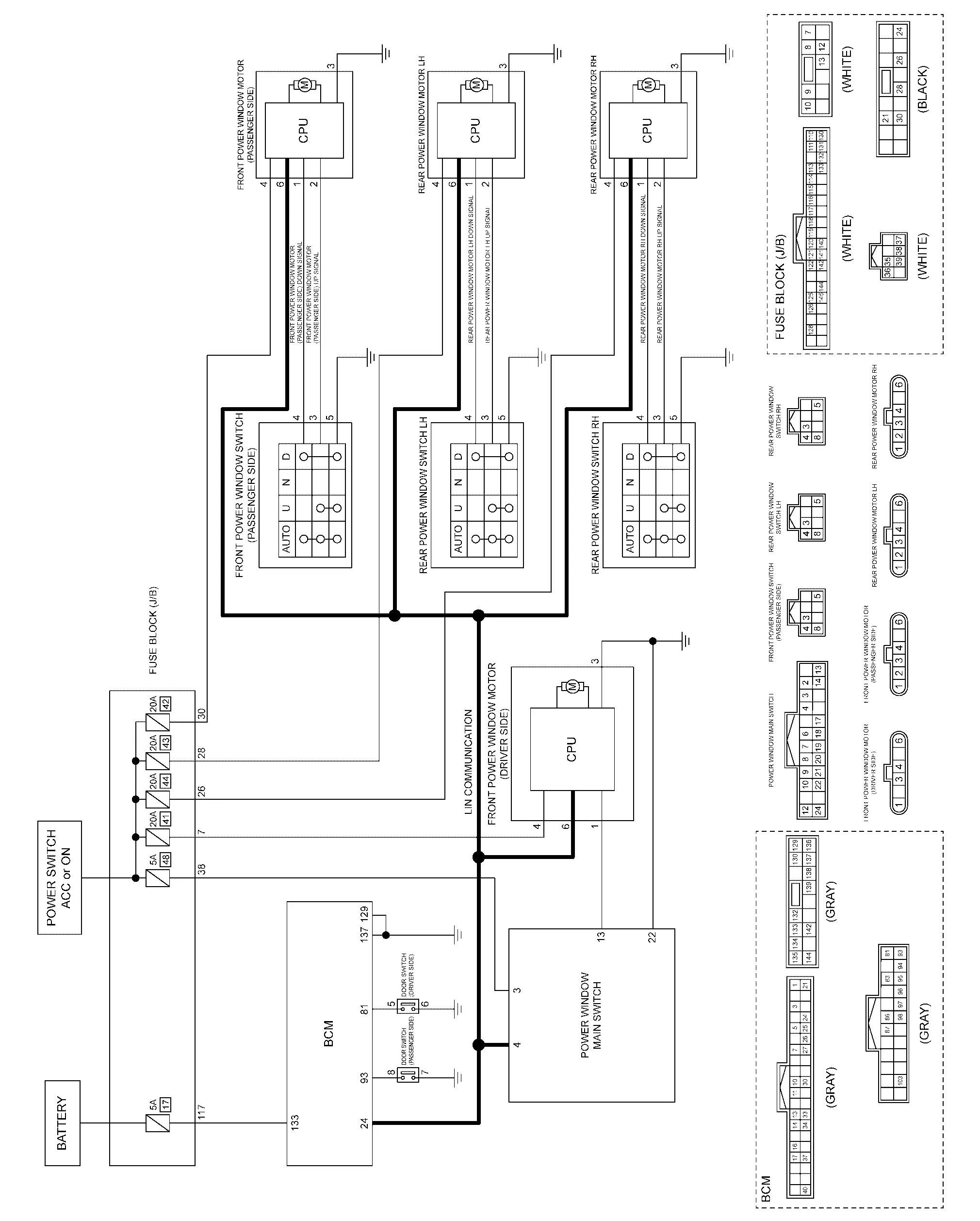
Circuit Diagram
Fail-safe

FAIL-SAFE CONTROL BY POWER WINDOW MOTOR

Power window motor switches power window operation to fail-safe control when malfunction is detected.

Detected itemJudgment conditionFail-safe operationRecovery condition
Non-Initialized condition When the motor integrated CPU detect door glass position non-initialized condition Auto UP operation (Anti-pinch) is forbidden Initialization completed
Thermal protection When the motor integrated CPU first detects thermal protection. DOWN operation is forbidden

After cooling, a certain amount of time has passed in the power switch ON state.

(Reference values: approximately 30 to 90 seconds, the elapsed time will be changed depending on how the temperature drops.)
When the motor integrated CPU detects thermal protection again when UP operated from the above state. Operation is forbidden (UP and DOWN is forbidden)
Consecutive reverse operation malfunction When the motor integrated CPU has detected consecutively 3 times the reverse operation Auto UP operation (Anti-pinch) is forbidden Approximately 10 seconds passed or the motor integrated CPU detect door glass fully close position

FAIL-SAFE CONTROL BY DTC

POWER WINDOW MOTOR

Power window motor performs fail-safe control when any DTC are detected.

DTCFail-safe
B2C41–04: Front power window motor FL Front power window motor (driver side) operation is stop or inching.
B2C42–04: Front power window motor FR Front power window motor (passenger side) operation is stop or inching.
B2C43–04: Rear power window motor RL Rear power window motor LH operation is stop or inching.
B2C44–04: Rear power window motor RR Rear power window motor RH operation is stop or inching.

POWER WINDOW MAIN SWITCH

Power window main switch performs fail-safe control when any DTC are detected.

DTCFail-safe

B2C40–04: Power window main switch

(When power window lock switch has been pressed for 30 seconds or more)

Power window lock status is continued.

[Power switch OFF (Auto ACC OFF status), and then power switch ON again to cancel the power window lock status.]