System

In this manual: System
How to Use This Manual — 1Precautions — 1Preparation — 1Vehicle Information — 1Basic Inspection — 1Preparation. Commercial Service Tools Or/and Repair Part — 1Description — 1Component Parts — 1System — 1Diagnosis System (vcm) — 1Ecu Diagnosis Information. Vcm — 1Ev Control System — 1Ev/hev (vcm) — 1Component Parts /circuit Diagnosis — 1Ev Control System — 1Periodic Maintenance. Ev System Warning Lamp — 1Removal and Installation. Vcm — 1Traction Motor System :: Front Traction Motor — 1Preparation — 1Description — 4Basic Inspection — 2Dtc Diagnosis — 2Component Parts /circuit Diagnosis — 1Traction Motor System :: Rear Traction Motor — 1Description — 4Basic Inspection — 2Dtc Diagnosis — 2Component Parts /circuit Diagnosis — 1Removal and Installation — 1Ev Battery System :: 66kwh Li-Ion Battery — 1Description — 4Basic Inspection — 2Dtc Diagnosis — 2Component Parts /circuit Diagnosis — 1Removal and Installation — 1Disassembly and Assembly — 2Service Data — 1Ev Battery System :: 91kwh Li-Ion Battery — 1Description — 4Basic Inspection — 2Dtc Diagnosis — 2Component Parts /circuit Diagnosis — 1Removal and Installation — 1Disassembly and Assembly — 1Service Data — 2Preparation. Vehicle Charging System — 1Vehicle Charging System :: Description — 1Component Parts — 2System — 1Diagnosis System (on-Board Charger) — 1Diagnosis System (dc/dc Converter) — 1Ecu Diagnosis Information — 1Vehicle Charging System — 1Charger/pd Module (on-Board Charger) — 1Cplc (cplc) — 1Dcdc (dc/dc Converter) — 1Component Parts/circuit Diagnosis — 1Symptom Diagnosis — 1Evse Inspection — 1Periodic Maintenance — 1Removal and Installation — 1Disassembly and Assembly — 1Preparation. High Voltage Cooling System — 1Description — 1Symptom Diagnosis. Overheating Cause Analysis — 1Periodic Maintenance — 1Coolant — 1Removal and Installation — 1Radiator — 1Service Data — 1Removal and Installation. Accelerator Control System — 1Reduction Gear: Re1f62a — 1Removal and Installation — 1Transaxle & Transmission :: Electric Shift — 1Description — 3Basic Inspection — 2Dtc Diagnosis — 2Component Parts /circuit Diagnosis — 1Removal and Installation — 1Rear Final Drive: Rn1r62a — 1Removal and Installation — 1Preparation. Front Axle System — 1Symptom Diagnosis. Noise, Vibration and Harshness (nvh) Troubleshooting — 1Periodic Maintenance — 1Removal and Installation — 1Service Data. Front Drive Shaft — 12wd — 14wd — 1Periodic Maintenance — 1Removal and Installation — 1Preparation. Front Suspension System — 1Symptom Diagnosis. Noise, Vibration and Harshness (nvh) Troubleshooting — 1Periodic Maintenance — 1Removal and Installation — 1Service Data — 1Symptom Diagnosis. Noise, Vibration and Harshness (nvh) Troubleshooting — 1Periodic Maintenance — 1Removal and Installation — 1Service Data — 1Preparation. Road Wheels & Tires System — 1Description — 1System — 1Ecu Diagnosis Information. Bcm (body Control Module) — 1Tpms — 1Dtc/circuit Diagnosis — 1Symptom Diagnosis — 1Periodic Maintenance. Road Wheels & Tires — 1Removal and Installation — 1Service Data — 1Preparation. Brake System — 1System Description — 1Component Parts — 1Ecu Diagnosis Information. Electrically-Driven Intelligent Brake Unit — 1Basic Inspection — 1Dtc/circuit Diagnosis — 1Symptom Diagnosis — 1Periodic Maintenance — 1Removal and Installation — 1Service Data — 1Preparation. Parking Brake System — 1System Description — 1Component Parts — 1System — 1Ecu Diagnosis Information. Abs Actuator and Electric Unit (control Unit) — 1Basic Inspection. Diagnosis and Repair Work Flow — 1Component Parts /circuit Diagnosis — 1Symptom Diagnosis — 1Removal and Installation — 1Brake Control System :: With Vdc — 1System Description — 3Basic Inspection — 2Dtc/circuit Diagnosis — 1Symptom Diagnosis — 2Removal and Installation — 1Brake Control System :: Automatic Brake Hold — 1System Description — 3Component Parts /circuit Diagnosis — 1Removal and Installation — 1Brake Control System :: E-Step — 1System Description — 3Removal and Installation — 1System Description — 1Ecu Diagnosis Information — 1Basic Inspection — 1Symptom Diagnosis — 1Rear Automatic Braking — 1System Description — 1Basic Inspection — 1Preparation. Steering System — 1System Description — 1Component Parts — 1Basic Inspection — 1Dtc/circuit Diagnosis — 1Symptom Diagnosis — 1Periodic Maintenance. Steering Wheel — 1Removal and Installation — 1Service Data — 1System Description — 1Component Parts — 1Steering Control System — 1Ecu Diagnosis Information. Power Steering Control Module — 1Dtc/circuit Diagnosis — 1Component Parts /circuit Diagnosis — 1Symptom Diagnosis — 1Removal and Installation. Power Steering Control Module — 1System Description — 1Removal and Installation — 1System Description — 1System — 1Basic Inspection. Diagnosis and Repair Work Flow — 1Dtc/circuit Diagnosis — 1Symptom Diagnosis — 1Component Parts — 1Basic Inspection — 1Removal and Installation — 1System Description — 1System — 1Ecu Diagnosis Information. Air Bag Diagnosis Sensor Unit — 1Basic Inspection — 1Dtc/circuit Diagnosis — 1Symptom Diagnosis — 1System Description. Description. Ventilation System — 1Removal and Installation — 1Preparation. Preparation — 1System Description — 1Basic Inspection — 1Symptom Diagnosis — 1Removal and Installation — 1Electric Compressor — 1Cooler Pipe and Hose — 1A/c Unit Assembly Cover — 1A/c Unit Assembly — 1Heater & Air Conditioning Control System :: Automatic Air Conditioning — 1System Description — 1Ecu Diagnosis Information — 1Basic Inspection — 2Dtc Diagnosis — 1Symptom Diagnosis — 1Removal and Installation — 2Preparation. Preparation — 1Symptom Diagnosis. Squeak and Rattle Trouble Diagnoses — 1Removal and Installation — 1Preparation. Instrument Panel — 1Component Parts — 1System — 1Ecu Diagnosis Information. Flexible Center Storage Control Module — 1Basic Inspection. Diagnosis and Repair Work Flow — 1Dtc/circuit Diagnosis — 1Symptom Diagnosis — 1Removal and Installation — 1Preparation. Preparation — 1Component Parts — 1System — 1Ecu Diagnosis Information. Driver Lumbar Support Control Module — 1Basic Inspection. Diagnosis and Repair Work Flow — 1Dtc/circuit Diagnosis — 1Symptom Diagnosis — 1Removal and Installation — 1System Description — 1System — 1Ecu Diagnosis Information — 1Basic Inspection — 1Dtc/circuit Diagnosis — 1Symptom Diagnosis — 1Manual Function Does Not Operate — 1Memory Function Does Not Operate — 1Removal and Installation — 1Preparation. Preparation — 1System Description — 1System (intelligent Key System) — 1Diagnosis System (bcm) — 1Ecu Diagnosis Information — 1Basic Inspection — 1Dtc/circuit Diagnosis — 1U2141-87 Can Comm Circuit — 1Power Supply and Ground Circuit — 1Symptom Diagnosis — 1Automatic Back Door Operation Does Not Operate — 1Back Door Does Not Open — 1Door Does Not Lock/unlock with Door Lock and Unlock Switch — 1Removal and Installation — 1Hood — 1Radiator Core Support — 1Charge Port Lid — 1Front Fender — 1Front Door — 1Rear Door — 1Back Door — 1Hood Lock — 1Front Door Lock — 1Rear Door Lock — 1Back Door Lock — 1Outside Key Antenna — 1System Description — 1System — 1Ecu Diagnosis Information. Inverter (front), Inverter (rear), Bcm, Intelligent Key Unit — 1Basic Inspection — 1Dtc/circuit Diagnosis — 1Symptom Diagnosis — 1Preparation — 1Symptom Diagnosis. Squeak and Rattle Trouble Diagnoses — 1Removal and Installation — 1System Description — 1Ecu Diagnosis Information — 1Basic Inspection — 1Dtc/circuit Diagnosis — 1Power Supply and Ground Circuit — 1Symptom Diagnosis — 1Front Passenger Side Power Window Does Not Operate — 1Rear Lh Side Power Window Does Not Operate — 1Rear Rh Side Power Window Does Not Operate — 1Removal and Installation. Power Window Main Switch — 1Preparation. Preparation — 1System Description — 1Ecu Diagnosis Information — 1Basic Inspection — 1Dtc/circuit Diagnosis — 1Power Supply and Ground Circuit — 1Sunroof Switch Assembly — 1Symptom Diagnosis — 1Auto Operation Does Not Operate — 1Removal and Installation — 1Preparation — 1Description — 1Symptom Diagnosis. Squeak and Rattle Trouble Diagnoses — 1Removal and Installation — 1Service Information — 6Repair Information — 1Precaution — 1Preparation — 1Removal and Installation — 1Service Data — 1Preparation. Preparation — 1Component Parts — 1System — 1Ecu Diagnosis Information — 1Wiring Diagram. Door Mirror — 1Basic Inspection. Diagnosis and Repair Work Flow — 1Dtc/circuit Diagnosis — 1Power Supply and Ground Circuit — 1Symptom Diagnosis — 1Removal and Installation — 1Exterior Lighting System :: Led Headlamp — 1System Description — 3Basic Inspection — 1Dtc/circuit Diagnosis — 1Symptom Diagnosis — 1Periodic Maintenance — 1Removal and Installation — 1System Description — 1System — 1Diagnosis System (bcm) — 1Ecu Diagnosis Information. Bcm, Intelligent Key Unit — 1Basic Inspection. Diagnosis and Repair Work Flow — 1Dtc/circuit Diagnosis — 1Symptom Diagnosis. Interior Lighting System Symptom — 1Removal and Installation — 1Service Data. Bulb Specifications — 1System Description — 1System — 1Ecu Diagnosis Information. Bcm, Ipdm E/r — 1Basic Inspection. Diagnosis and Repair Work Flow — 1Dtc/circuit Diagnosis — 1Symptom Diagnosis — 1Removal and Installation — 1System Description — 1Ecu Diagnosis Information. Bcm — 1Basic Inspection. Diagnosis and Repair Work Flow — 1Dtc/circuit Diagnosis — 1Symptom Diagnosis — 1Removal and Installation — 1Preparation. Preparation — 1Removal and Installation. Horn — 1Preparation. Commercial Service Tools Or/and Repair Part — 1System Description — 1Component Parts — 1Ecu Diagnosis Information. Approaching Vehicle Sound for Pedestrians (vsp) Control Unit — 1Approaching Vehicle Sound for Pedestrians (vsp) — 1Vsp [approaching Vehicle Sound for Pedestrians (vsp) Control Unit] — 1Approaching Vehicle Sound for Pedestrians (vsp) System — 1Removal and Installation — 1Removal and Installation — 1Wireless Charger — 1System Description — 1Basic Inspection — 1Dtc/circuit Diagnosis — 1Removal and Installation — 1Component Parts — 1System — 1Diagnosis System (bcm) — 1Ecu Diagnosis Information. Bcm — 1Basic Inspection — 1Dtc/circuit Diagnosis — 1Symptom Diagnosis — 1Removal and Installation — 1Can Fundamental — 1Description — 1Trouble Diagnosis — 1Can (controller Area Network) — 1Description — 1
~8min read
  • Srs Air Bag System
  • Warning/indicator/chime List

Srs Air Bag System Nissan Ariya 2026

System Description

SYSTEM DIAGRAM
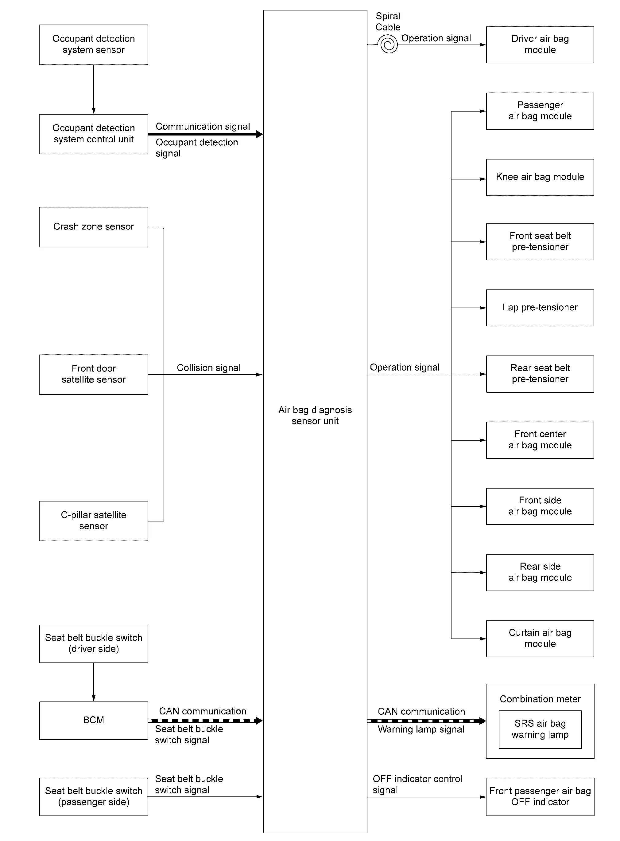
ComponentFunction
Occupant detection system sensor Refer to Occupant Detection System Sensor.
Occupant detection system control unit Refer to Occupant Detection System Control Unit.
Crash zone sensor Refer to Crash Zone Sensor.
Front door satellite sensor Refer to Satellite Sensor.
C-pillar satellite sensor Refer to Satellite Sensor.
Seat belt buckle switch Fastening or not fastening of seat belt judged. This judge is used for control of front air bag system.
BCM BCM transmits the seat belt buckle switch (driver side) signal to air bag diagnosis sensor unit via CAN communication.
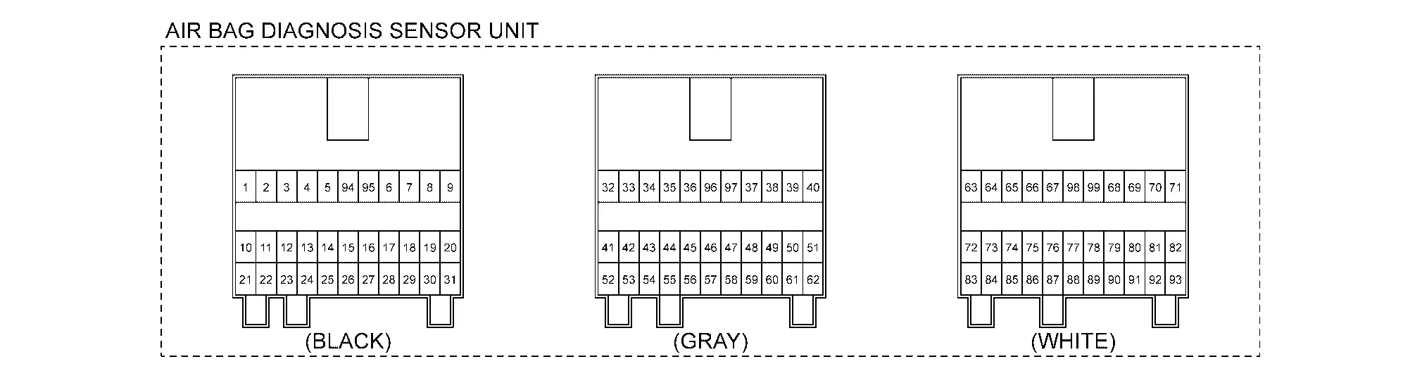
Air bag diagnosis sensor unit Refer to Air Bag Diagnosis Sensor Unit.
Spiral cable Refer to Spiral Cable.
Driver air bag module Refer to Driver Air Bag Module.
Passenger air bag module Refer to Passenger Air Bag Module.
Knee air bag module Refer to Driver Knee Air Bag Module and Passenger Knee Air Bag Module.
Front seat belt pre-tensioner Refer to Seat Belt Pre-tensioner with Load Limiter.
Lap pre-tensioner Refer to Double Pre-tensioner Seat Belt.
Rear seat belt pre-tensioner Refer to Seat Belt Pre-tensioner with Load Limiter.
Front center air bag module Refer to Front Center Air Bag Module.
Front side air bag module Refer to Front Side Air Bag Module.
Rear side air bag module Refer to Rear Side Air Bag Module.
Curtain air bag module Refer to Curtain Air Bag Module.
Combination meter (SRS air bag warning lamp) Refer to Air Bag Warning Lamp.
Front passenger air bag OFF indicator Refer to Front Passenger Air Bag OFF Indicator.

SYSTEM DESCRIPTION

Supplemental Restraint System (SRS) activates air bag module and seat belt pre-tensioner when it detects a collision that is more than the specified limit. Together with other safety devices, it reduces the impact that occupant receives when Nissan Ariya vehicle collision occurs. Air bag diagnosis sensor unit supplies power supply to air bag module and pre-tensioner seat belt when deceleration that is more than the specified limit is detected by G sensor in air bag diagnosis sensor unit, crash zone sensor and each satellite sensor. Air bag module is composed of electric igniter (squib), filter, pyrotechnic material, and gas generating material. When air bag module receives a signal from air bag diagnosis sensor unit, air bag module ignites pyrotechnic material using electric igniter (squib) so that gas generating material generates high temperature nitrogen gas. The gas through filter activates air bag. At the same time, pre-tensioner seat belt receives power supply from air bag diagnosis sensor unit, gas generator is activated, and then gas is generated. The pressure of the generated gas causes the balls inside of pipe to move and the shaft to rotate and retract the shoulder belt. Similarly, the piston inside of pipe moves, and retracts the lap belt connected to the wire.

AIR BAG DIAGNOSIS SENSOR UNIT FUNCTIONS

Air bag diagnosis sensor unit has the following functions.

  • Detects a collision and supplies the energy for deploying air bag and seat belt pre-tensioner.

  • Detects and records electrical malfunction in air bag system and seat belt pre-tensioner system, and turns SRS air bag warning lamp ON.

  • Detects and records the deployment of air bag and seat belt pre-tensioner, and turns ON SRS air bag warning lamp.

  • Indicates the malfunction record via CONSULT.

SRS AIR BAG WARNING LAMP

  • Detects electrical malfunction in air bag system and seat belt pre-tensioner system, and turns SRS air bag warning lamp ON.

  • Detects deployment malfunction in air bag system and seat belt pre-tensioner system, and turns SRS air bag warning lamp ON.

  • Air bag diagnosis sensor unit warns the driver by turning SRS air bag warning lamp ON when air bag diagnosis sensor unit detects battery low voltage. SRS air bag warning lamp turns ON when a voltage value at which air bag diagnosis sensor unit cannot operate normally (9 V or less) is detected. After starting to turn ON, SRS air bag warning lamp turns OFF when air bag diagnosis sensor unit detects the normal value of battery voltage.

  • Air bag diagnosis sensor unit warns the driver by turning SRS air bag warning lamp ON when air bag diagnosis sensor unit detects battery high voltage. SRS air bag warning lamp turns ON when a voltage value at which air bag diagnosis sensor unit cannot operate normally (16 V or more) is detected. After starting to turn ON, SRS air bag warning lamp turns OFF when air bag diagnosis sensor unit detects the normal value of battery voltage.

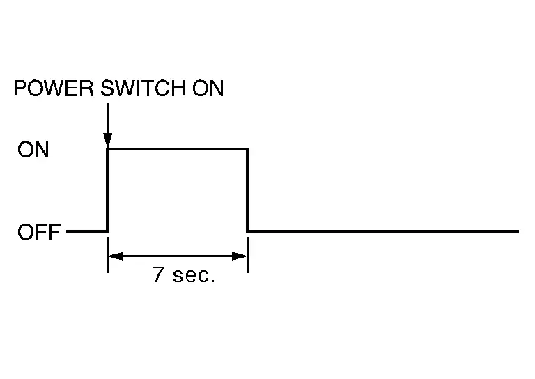
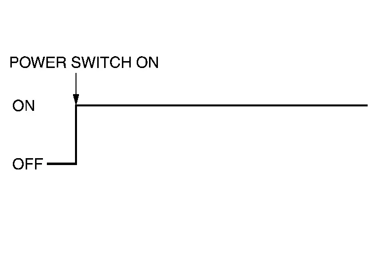
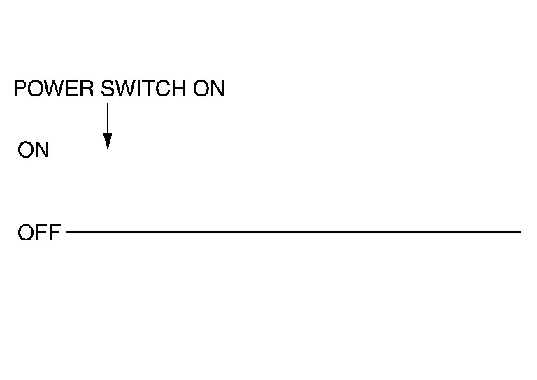
SRS air bag warning lamp operationSRS condition
No malfunction is detected
  • Air bag is deployed

  • Seat belt pre-tensioner is deployed

  • The system is malfunctioning

  • Battery voltage is low (9 V or less) or high battery voltage (16 V or more)

  • Air bag diagnosis sensor unit is malfunctioning

  • SRS air bag warning lamp circuit is malfunctioning

  • Combination meter is malfunctioning

COLLISION MODES

The operation of SRS is different depending on the collision modes applications.

SRS configurations that are activated for the following collision modes.

×: Apply —: Not apply

SRS configurationFrontal collisionLeft side collisionRight side collisionRolloverRear collision
Driver air bag module × —*1 —*1 — —*1
Passenger air bag module × —*1 —*1 — —*1
Knee air bag module LH × —*1 —*1 — —*1
Knee air bag module RH × —*1 —*1 — —*1
Front seat belt pre-tensioner LH × × × × —*1*2*3
Front seat belt pre-tensioner RH × × × × —*1*2*3
Lap pre-tensioner LH × × × × —*1*2*3
Lap pre-tensioner RH × × × × —*1*2*3
Rear seat belt pre-tensioner LH × × × × —*1*2*3
Rear seat belt pre-tensioner RH × × × × —*1*2*3
Front center air bag module —*2*3 × × × —*2*3
Front side air bag module LH —*2 × —*2 — —*2
Front side air bag module RH —*3 —*3 × — —*3
Rear side air bag module LH —*2 × —*2 — —*2
Rear side air bag module RH —*3 —*3 × — —*3
Curtain air bag module LH —*2 × —*2 × —*2
Curtain air bag module RH —*3 —*3 × × —*3

*1: SRS may be activated when an excessive impact is applied toward the front of the vehicle.

*2: SRS may be activated when an excessive impact is applied toward the left of the vehicle.

*3: SRS may be activated when an excessive impact is applied toward the right of the vehicle.

OCCUPANT DETECTION SYSTEM

This Occupant Detection System has the following functions.

  • Suppress the deployment of passenger air bag and knee air bag (passenger side) when front passenger seat is empty, or when occupied by child and child-seat. Turns ON front passenger air bag OFF indicator when front passenger seat is occupied by child-seat and child.

  • Indicates the malfunctioning record by CONSULT.

  • When “zero point reset” for occupant detection system is incomplete, CONSULT indicates that “zero point reset” is incomplete.

    This function is applied to NISSAN genuine parts only.

Status (front passenger seat)Passenger air bag and knee air bag (passenger side)Front passenger air bag OFF indicatorSRS air bag warning lamp
Empty Suppress ON OFF
An object Suppress ON OFF
Child/ child-seat Suppress ON OFF
Adult Enable to deploy OFF OFF
Malfunction Suppress ON ON

Zero point reset

Not yet performed (NISSAN genuine parts only)
Suppress ON ON

Active Vent Function

Air bag diagnosis sensor unit opens vent of passenger air bag module by passenger side occupant detecting condition if necessary. The pressure of the deployed air bag falls, and the passenger side occupant is take care of appropriately.

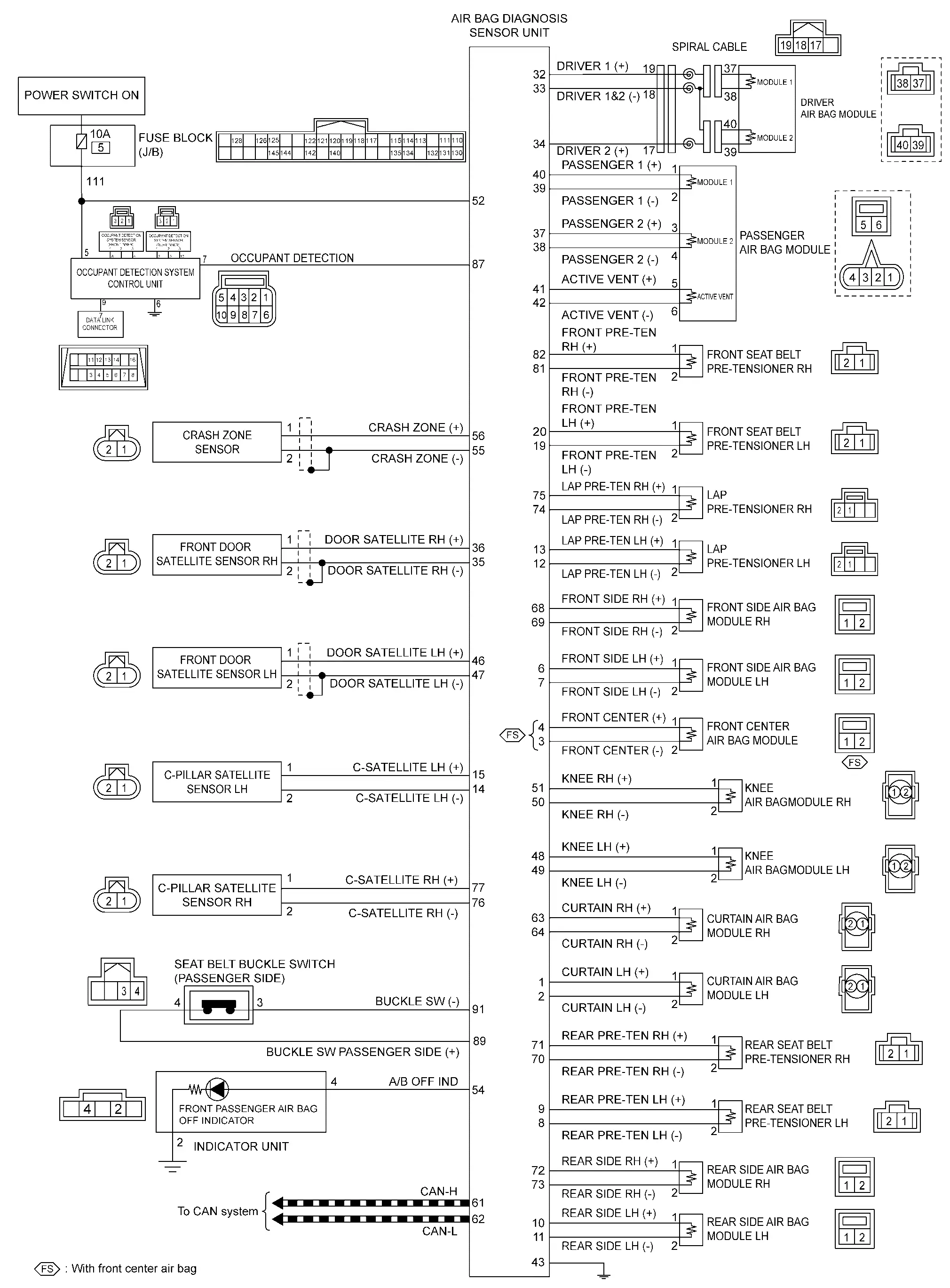
Circuit Diagram
Warning/indicator/chime List Nissan Ariya SUV

Warning Lamp/Indicator Lamp

ItemDesignReference
SRS air bag warning lamp For layout, refer to Design.
For function, refer to SRS Air Bag Warning Lamp.