System
- Electric Parking Brake System
- Parking Brake Warning
Electric Parking Brake System Nissan Ariya first Gen
System Description
The electric parking brake system uses the signal from the parking brake switch to have the ABS actuator and electric unit (control unit) operate the parking brake actuator to apply and release the parking brake.
The parking brake switch is placed in the instrument lower panel so that it can be operated close at hand (applied/released).
When the parking brake is operated, the electric parking brake warning lamp in the combination meter and the parking brake switch indicator turn ON.
When the parking brake is released, the electric parking brake warning lamp in the combination meter and the parking brake switch indicator turn OFF.
When a malfunction occurs in the electric parking brake system, brake system warning lamp turn ON, electric parking brake warning lamp turn ON/OFF (depends on the electric parking brake system) or blink, and parking brake switch indicator turn ON/OFF (depends on the electric parking brake system) or blink, and the function for entering the fail-safe status is held.
When a malfunction occurs in the electric parking brake system, the parking brake can be mechanically released. Refer to Work Procedure.
OPERATION
When the parking brake switch is pulled, a parking brake operation signal is transmitted from the ABS actuator and electric unit (control unit) to the parking brake actuator.
When the parking brake actuator receives a parking brake operation signal, it activates the motor in the parking brake actuator.
When the motor is operated, rotating torque is generated, and the force is arose to press against the piston of the rear brake caliper assembly via gears.
The piston is pushed out by the rotating torque, and the electric parking brake operates by pressing the brake pad against the disc rotor.
RELEASE
When the parking brake switch is pushed, a parking brake release signal is transmitted from the ABS actuator and electric unit (control unit) to the parking brake actuator.
When parking brake actuator receives electric parking brake release request signal, the motor in parking brake actuator operates (reverse rotation against operation).
When to motor is operated, rotating torque is released, and the force is released to press against the piston of the rear brake caliper assembly via gears.
Electric parking brake is released by separating brake pad and disc rotor.
SYSTEM DIAGRAM
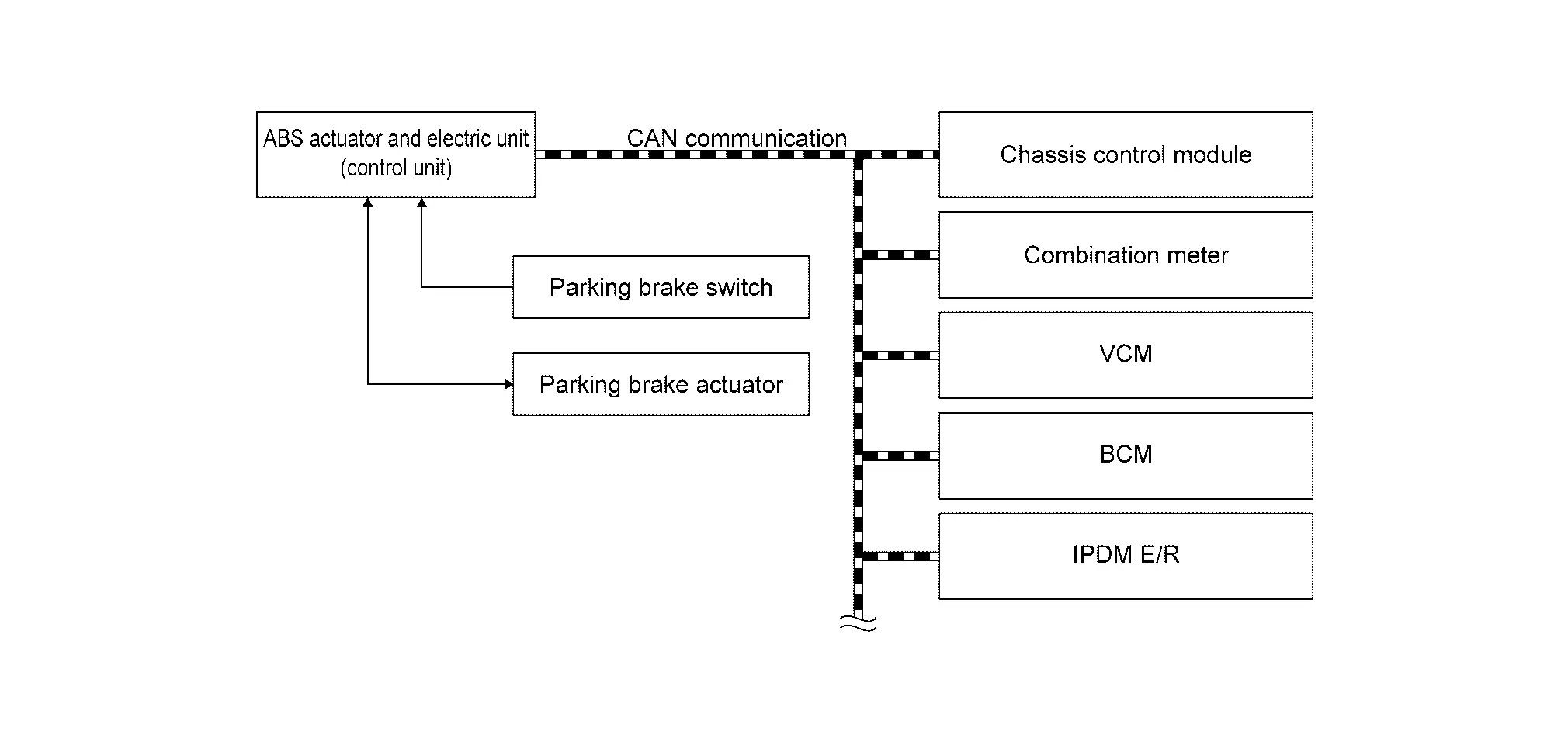
INPUT SIGNAL AND OUTPUT SIGNAL
Major signal transmission between each unit via communication lines is shown in the following table.
| Component | Signal description |
|---|---|
| ABS actuator and electric unit (control unit) | Refer to Component Description. |
| Parking brake actuator | Refer to Component Description. |
| Parking brake switch | Refer to Component Description. |
| Chassis control module | Mainly transmits the following signals to ABS actuator and electric unit (control unit) via CAN communication.
Mainly receives the following signals from ABS actuator and electric unit (control unit) via CAN communication.
|
| Combination meter | Mainly receives the following signals from ABS actuator and electric unit (control unit) via CAN communication.
|
| VCM | Mainly transmits the following signals to ABS actuator and electric unit (control unit) via CAN communication.
|
| BCM | Mainly transmits the following signals to ABS actuator and electric unit (control unit) via CAN communication.
|
| IPDM E/R | Mainly transmits the following signals to ABS actuator and electric unit (control unit) via CAN communication.
|
ELECTRIC PARKING BRAKE OPERATION
Normal Operation
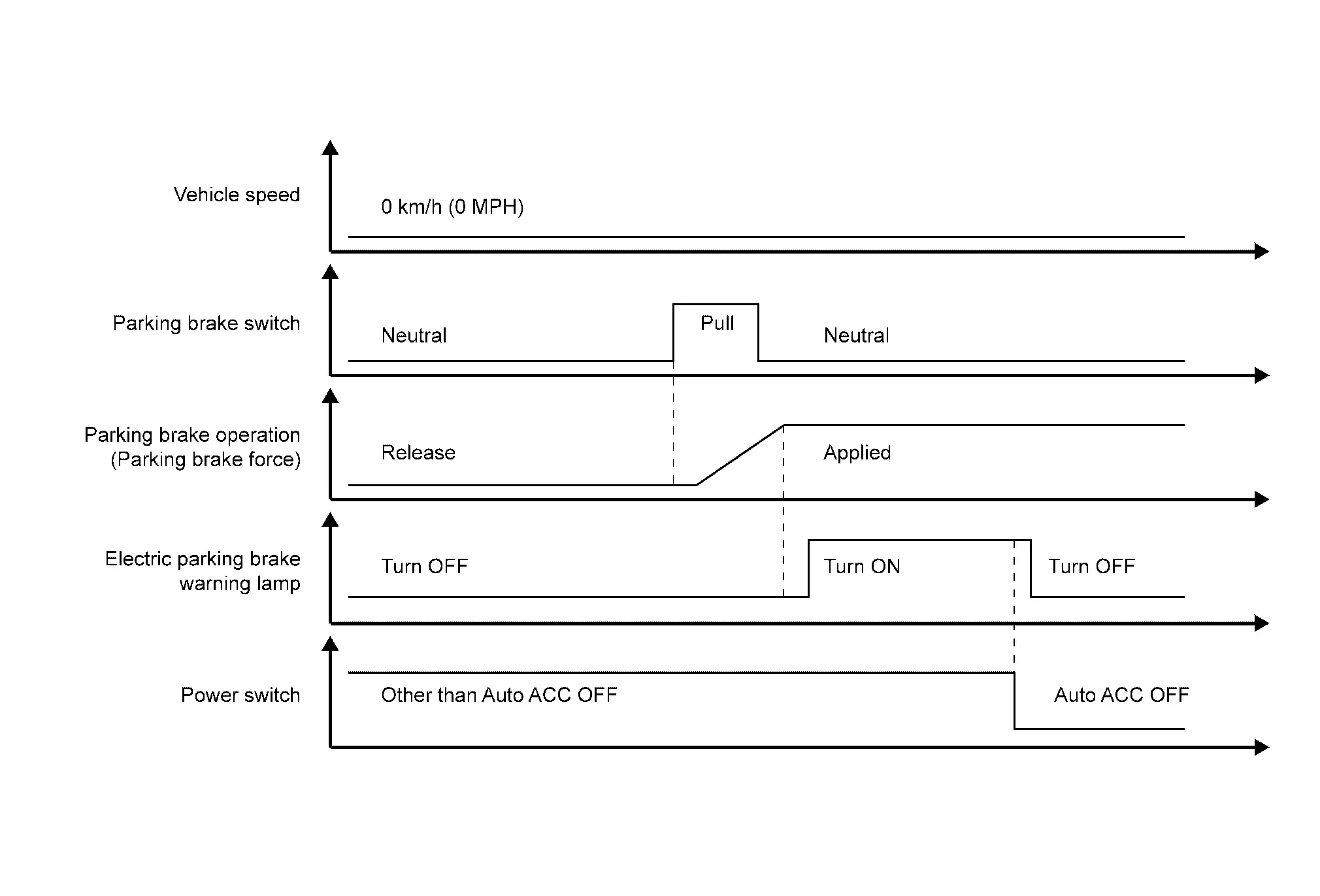
When the parking brake switch is pulled while the vehicle is stopped, the electric parking brake operates. (The motor in the parking brake actuator starts generating rotating torque.)
When the electric parking brake braking force reaches the prescribed value (rotating torque generated by the motor in the parking brake actuator), the electric parking brake warning lamp turns ON.
When the power switch is OFF, the electric parking brake warning lamp is turn OFF.
Changing from Automatic Brake Hold to Parking Brake
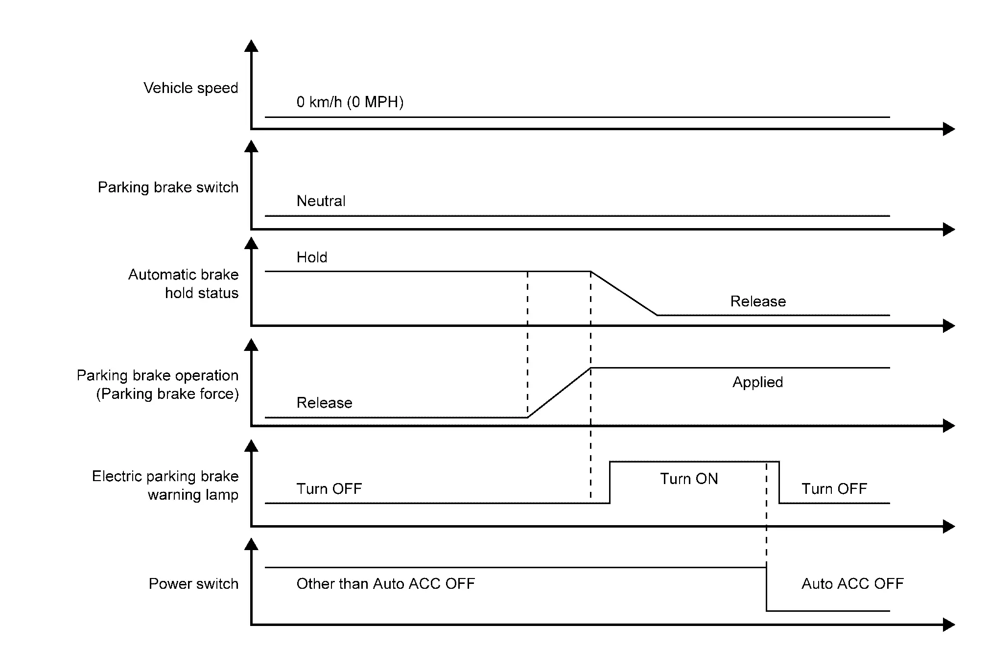
If any of the following conditions are met, electric parking brake operates automatically. (The braking method for stopping the Nissan Ariya vehicle is changed from automatic brake hold to electric parking brake.)
Automatic brake hold operates for approximately 3 minutes
Driver seat belt is unfastened while automatic brake hold is being applied
Power switch is OFF
A malfunction is detected in automatic brake hold
Driver door is opened
The electric shift selector is in the P position
When the electric parking brake effectiveness reaches the specified value (rotating torque generated by the motor in the parking brake actuator), electric parking brake warning lamp turns ON.
When the power switch is OFF, the electric parking brake warning lamp is turn OFF.
Normal Release (Power switch ON)
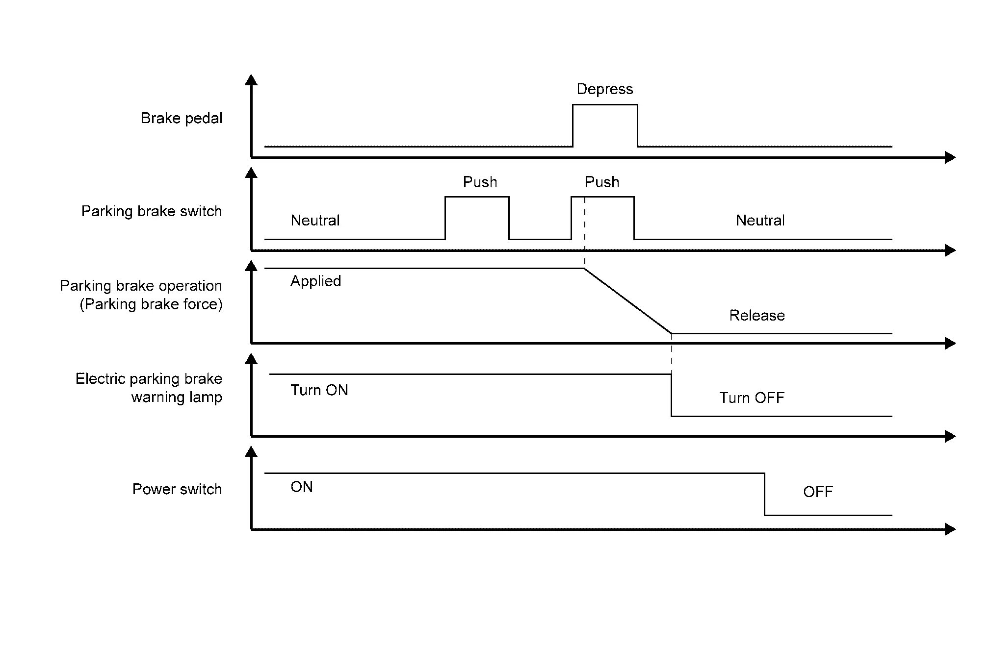
The parking brake is released when the parking brake switch is pushed while the brake pedal is depressed, the power switch is ON, and the electric parking brake is operating.
When release of the electric parking brake is completed (it means no rotating torque generated by the motor in the parking brake actuator), the electric parking brake warning lamp turns OFF.
Normal Release (Other Power switch ON)

The electric parking brake cannot be released if only parking brake switch is pushed while the power switch is OFF, the electric parking brake is applied, and the brake pedal is depressed.
The electric parking brake warning lamp turns OFF.
Automatic Release
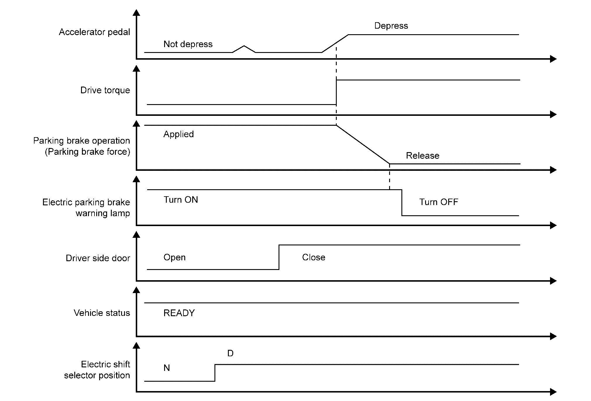
The parking brake automatically releases under the following conditions.
Nissan Ariya Vehicle to READY
The electric shift selector is in the D or R position
Driver door is closed
The accelerator pedal is depressed
When traction motor torque necessary for travelling is generated
When release of the electric parking brake is completed (it means no rotating torque generated by the motor in the parking brake actuator), the electric parking brake warning lamp turns OFF.
Driving
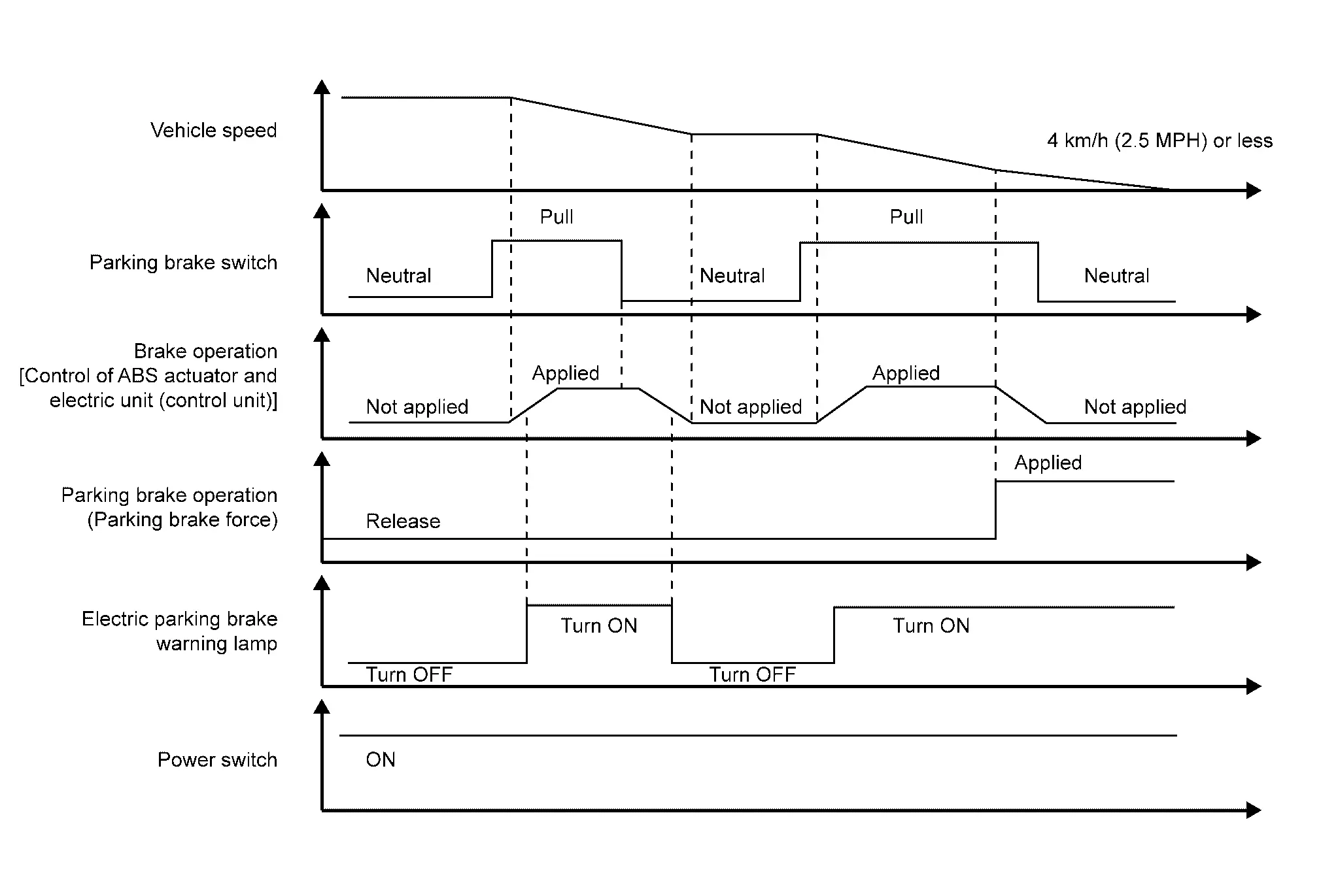
When parking brake switch is pulled while the vehicle is stopping [Vehicle speed is 4 km/h or less.], the electric parking brake starts the operation (the motor in the parking brake actuator starts the rotation). And then the electric parking brake warning lamp is turned ON.
When the parking brake switch is pulled while travelling, a command is transmitted to the ABS actuator and electric unit (control unit), and it applies brake on four wheels to reduce Nissan Ariya vehicle speed.
CONDITION FOR TURN ON THE WARNING LAMP AND INFORMATION DISPLAY
About valve check, refer to following.
Electric parking brake warning lamp: Refer to Electric Parking Brake Warning Lamp.
Brake system warning lamp: Refer to Brake System Warning Lamp.
| Condition (status) | Electric parking brake warning lamp  | Master warning lamp  | Brake system warning lamp  | Parking brake switch indicator | Warning buzzer | Information display |
|---|---|---|---|---|---|---|
| Electric parking brake system is operating | ON | OFF | OFF | ON | OFF | — |
| Electric parking brake system is released | OFF | OFF | OFF | OFF | OFF | — |
| The parking brake switch is pushed without depressing the brake pedal. | ON | OFF | OFF | ON | OFF | Press brake pedal |
| The accelerator pedal is depressed with the Nissan Ariya vehicle is READY state and the driver door is open. | ON | OFF | OFF | ON | OFF | Release parking brake |
| The electric parking brake is operated with the parking brake switch kept pulled during driving. | ON | ON | OFF | ON | ON | Release parking brake |
| When measuring the braking force | ON | OFF | OFF | ON | OFF | — |
| Electric parking brake system is malfunctioning | ON/OFF (Depends on the status of the electric parking brake system.) | OFF | ON | ON/OFF (Depends on the status of the electric parking brake system.) | OFF | — |
| The electric parking brake braking force is insufficient (Nissan Ariya vehicle is moving backward). | Blinking | ON | ON | Blinking | ON | Press brake pedal |
| The combination meter cannot receive signals from the ABS actuator and electric unit (control unit) via CAN communication. | Blinking | OFF | ON | ON/OFF (Depends on the status of the electric parking brake system.) | OFF | — |
| A malfunction of the parking brake switch is detected. | ON/OFF (Depends on the status of the electric parking brake system.) | OFF | ON | ON/OFF (Depends on the status of the electric parking brake system.) | OFF | — |
| The parking brake switch is operated while a malfunction of the parking brake switch is detected. | Blinking | OFF | ON | Blinking | OFF | — |
| Release of the electric parking brake is inhibited detecting malfunctions of other control units. | ON/OFF (Depends on the status of the electric parking brake system.) | OFF | ON | ON/OFF (Depends on the status of the electric parking brake system.) | OFF | — |
| Electric parking brake system does not operate (malfunction check not possible). | Blinking | OFF | ON | Blinking | OFF | — |
Circuit Diagram
Refer to Circuit Diagram.
Fail-safe
Refer to Fail-safe.
Warning / Indicator / Chime List
| Name | Design | Layout/Function |
|---|---|---|
| Electric parking brake warning lamp |  |
For layout: Refer to Design. |
| For function: Refer to Electric Parking Brake Warning Lamp. |
| Brake system warning lamp | |
For layout: Refer to Design. |
| For function: Refer to Brake System Warning Lamp. |
| Name | Design | Layout/Function |
|---|---|---|
| Electric parking brake warning lamp | |
For layout: Refer to Design. |
| For function: Refer to Electric Parking Brake Warning Lamp. |
| Brake system warning lamp | |
For layout: Refer to Design. |
| For function: Refer to Brake System Warning Lamp. |
Parking Brake Warning Nissan Ariya SUV
System Description
DESIGN/PURPOSE
Warns the driver of the necessity of depressing the brake pedal.
Warns the driver of the necessity of releasing the electric parking brake.
- Press brake pedal
- Release parking brake
SYNCHRONIZATION WITH MASTER WARNING LAMP
Applicable
Refer to Master Warning Lamp.
SYNCHRONIZATION WITH WARNING CHIME
Applicable
Refer to System Description.
SYSTEM DIAGRAM
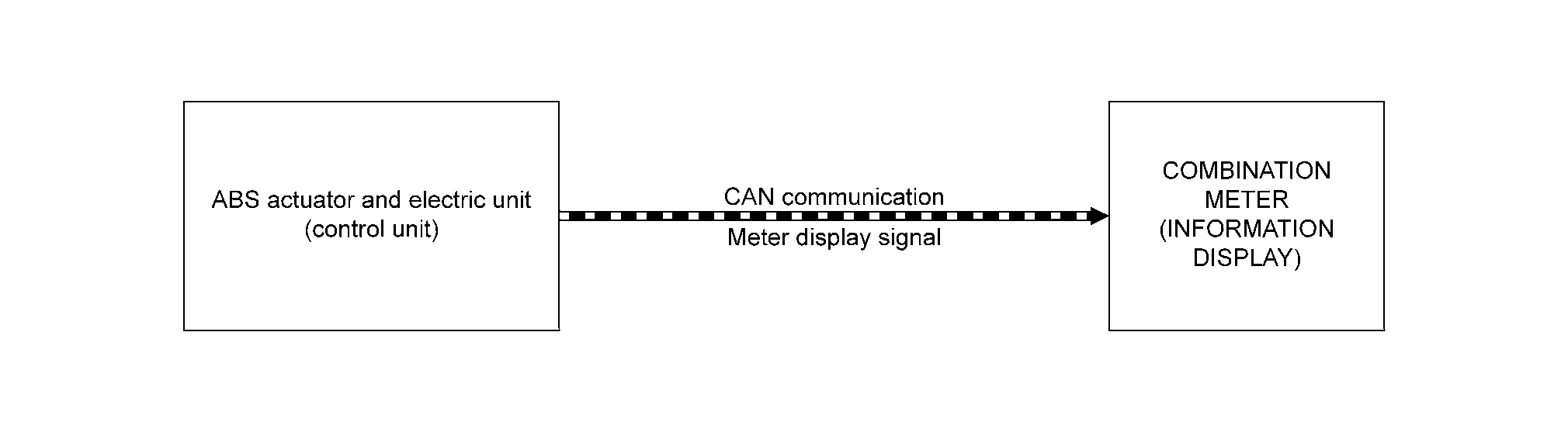
SIGNAL PATH
The ABS actuator and electric unit (control unit) transmits a signal to the combination meter via CAN communication under the conditions bellow:
When necessary to depress the brake pedal.
When necessary to release the parking brake.
When the following conditions are satisfied (power switch ON)
The parking brake switch is pushed without depressing the brake pedal.
The electric parking brake is operated with the parking brake switch kept pulled during driving.
The electric parking brake braking force is insufficient (Nissan Ariya vehicle is moving backward).
The vehicle moved while the electric parking brake is being applied.