Removal and Installation

In this manual: Removal and Installation
How to Use This Manual — 1Precautions — 1Preparation — 1Vehicle Information — 1Basic Inspection — 1Preparation. Commercial Service Tools Or/and Repair Part — 1Description — 1Component Parts — 1System — 1Diagnosis System (vcm) — 1Ecu Diagnosis Information. Vcm — 1Ev Control System — 1Ev/hev (vcm) — 1Component Parts /circuit Diagnosis — 1Ev Control System — 1Periodic Maintenance. Ev System Warning Lamp — 1Removal and Installation. Vcm — 1Traction Motor System :: Front Traction Motor — 1Preparation — 1Description — 4Basic Inspection — 2Dtc Diagnosis — 2Component Parts /circuit Diagnosis — 1Traction Motor System :: Rear Traction Motor — 1Description — 4Basic Inspection — 2Dtc Diagnosis — 2Component Parts /circuit Diagnosis — 1Removal and Installation — 1Ev Battery System :: 66kwh Li-Ion Battery — 1Description — 4Basic Inspection — 2Dtc Diagnosis — 2Component Parts /circuit Diagnosis — 1Removal and Installation — 1Disassembly and Assembly — 2Service Data — 1Ev Battery System :: 91kwh Li-Ion Battery — 1Description — 4Basic Inspection — 2Dtc Diagnosis — 2Component Parts /circuit Diagnosis — 1Removal and Installation — 1Disassembly and Assembly — 1Service Data — 2Preparation. Vehicle Charging System — 1Vehicle Charging System :: Description — 1Component Parts — 2System — 1Diagnosis System (on-Board Charger) — 1Diagnosis System (dc/dc Converter) — 1Ecu Diagnosis Information — 1Vehicle Charging System — 1Charger/pd Module (on-Board Charger) — 1Cplc (cplc) — 1Dcdc (dc/dc Converter) — 1Component Parts/circuit Diagnosis — 1Symptom Diagnosis — 1Evse Inspection — 1Periodic Maintenance — 1Removal and Installation — 1Disassembly and Assembly — 1Preparation. High Voltage Cooling System — 1Description — 1Symptom Diagnosis. Overheating Cause Analysis — 1Periodic Maintenance — 1Coolant — 1Removal and Installation — 1Radiator — 1Service Data — 1Removal and Installation. Accelerator Control System — 1Reduction Gear: Re1f62a — 1Removal and Installation — 1Transaxle & Transmission :: Electric Shift — 1Description — 3Basic Inspection — 2Dtc Diagnosis — 2Component Parts /circuit Diagnosis — 1Removal and Installation — 1Rear Final Drive: Rn1r62a — 1Removal and Installation — 1Preparation. Front Axle System — 1Symptom Diagnosis. Noise, Vibration and Harshness (nvh) Troubleshooting — 1Periodic Maintenance — 1Removal and Installation — 1Service Data. Front Drive Shaft — 12wd — 14wd — 1Periodic Maintenance — 1Removal and Installation — 1Preparation. Front Suspension System — 1Symptom Diagnosis. Noise, Vibration and Harshness (nvh) Troubleshooting — 1Periodic Maintenance — 1Removal and Installation — 1Service Data — 1Symptom Diagnosis. Noise, Vibration and Harshness (nvh) Troubleshooting — 1Periodic Maintenance — 1Removal and Installation — 1Service Data — 1Preparation. Road Wheels & Tires System — 1Description — 1System — 1Ecu Diagnosis Information. Bcm (body Control Module) — 1Tpms — 1Dtc/circuit Diagnosis — 1Symptom Diagnosis — 1Periodic Maintenance. Road Wheels & Tires — 1Removal and Installation — 1Service Data — 1Preparation. Brake System — 1System Description — 1Component Parts — 1Ecu Diagnosis Information. Electrically-Driven Intelligent Brake Unit — 1Basic Inspection — 1Dtc/circuit Diagnosis — 1Symptom Diagnosis — 1Periodic Maintenance — 1Removal and Installation — 1Service Data — 1Preparation. Parking Brake System — 1System Description — 1Component Parts — 1System — 1Ecu Diagnosis Information. Abs Actuator and Electric Unit (control Unit) — 1Basic Inspection. Diagnosis and Repair Work Flow — 1Component Parts /circuit Diagnosis — 1Symptom Diagnosis — 1Removal and Installation — 1Brake Control System :: With Vdc — 1System Description — 3Basic Inspection — 2Dtc/circuit Diagnosis — 1Symptom Diagnosis — 2Removal and Installation — 1Brake Control System :: Automatic Brake Hold — 1System Description — 3Component Parts /circuit Diagnosis — 1Removal and Installation — 1Brake Control System :: E-Step — 1System Description — 3Removal and Installation — 1System Description — 1Ecu Diagnosis Information — 1Basic Inspection — 1Symptom Diagnosis — 1Rear Automatic Braking — 1System Description — 1Basic Inspection — 1Preparation. Steering System — 1System Description — 1Component Parts — 1Basic Inspection — 1Dtc/circuit Diagnosis — 1Symptom Diagnosis — 1Periodic Maintenance. Steering Wheel — 1Removal and Installation — 1Service Data — 1System Description — 1Component Parts — 1Steering Control System — 1Ecu Diagnosis Information. Power Steering Control Module — 1Dtc/circuit Diagnosis — 1Component Parts /circuit Diagnosis — 1Symptom Diagnosis — 1Removal and Installation. Power Steering Control Module — 1System Description — 1Removal and Installation — 1System Description — 1System — 1Basic Inspection. Diagnosis and Repair Work Flow — 1Dtc/circuit Diagnosis — 1Symptom Diagnosis — 1Component Parts — 1Basic Inspection — 1Removal and Installation — 1System Description — 1System — 1Ecu Diagnosis Information. Air Bag Diagnosis Sensor Unit — 1Basic Inspection — 1Dtc/circuit Diagnosis — 1Symptom Diagnosis — 1System Description. Description. Ventilation System — 1Removal and Installation — 1Preparation. Preparation — 1System Description — 1Basic Inspection — 1Symptom Diagnosis — 1Removal and Installation — 1Electric Compressor — 1Cooler Pipe and Hose — 1A/c Unit Assembly Cover — 1A/c Unit Assembly — 1Heater & Air Conditioning Control System :: Automatic Air Conditioning — 1System Description — 1Ecu Diagnosis Information — 1Basic Inspection — 2Dtc Diagnosis — 1Symptom Diagnosis — 1Removal and Installation — 2Preparation. Preparation — 1Symptom Diagnosis. Squeak and Rattle Trouble Diagnoses — 1Removal and Installation — 1Preparation. Instrument Panel — 1Component Parts — 1System — 1Ecu Diagnosis Information. Flexible Center Storage Control Module — 1Basic Inspection. Diagnosis and Repair Work Flow — 1Dtc/circuit Diagnosis — 1Symptom Diagnosis — 1Removal and Installation — 1Preparation. Preparation — 1Component Parts — 1System — 1Ecu Diagnosis Information. Driver Lumbar Support Control Module — 1Basic Inspection. Diagnosis and Repair Work Flow — 1Dtc/circuit Diagnosis — 1Symptom Diagnosis — 1Removal and Installation — 1System Description — 1System — 1Ecu Diagnosis Information — 1Basic Inspection — 1Dtc/circuit Diagnosis — 1Symptom Diagnosis — 1Manual Function Does Not Operate — 1Memory Function Does Not Operate — 1Removal and Installation — 1Preparation. Preparation — 1System Description — 1System (intelligent Key System) — 1Diagnosis System (bcm) — 1Ecu Diagnosis Information — 1Basic Inspection — 1Dtc/circuit Diagnosis — 1U2141-87 Can Comm Circuit — 1Power Supply and Ground Circuit — 1Symptom Diagnosis — 1Automatic Back Door Operation Does Not Operate — 1Back Door Does Not Open — 1Door Does Not Lock/unlock with Door Lock and Unlock Switch — 1Removal and Installation — 1Hood — 1Radiator Core Support — 1Charge Port Lid — 1Front Fender — 1Front Door — 1Rear Door — 1Back Door — 1Hood Lock — 1Front Door Lock — 1Rear Door Lock — 1Back Door Lock — 1Outside Key Antenna — 1System Description — 1System — 1Ecu Diagnosis Information. Inverter (front), Inverter (rear), Bcm, Intelligent Key Unit — 1Basic Inspection — 1Dtc/circuit Diagnosis — 1Symptom Diagnosis — 1Preparation — 1Symptom Diagnosis. Squeak and Rattle Trouble Diagnoses — 1Removal and Installation — 1System Description — 1Ecu Diagnosis Information — 1Basic Inspection — 1Dtc/circuit Diagnosis — 1Power Supply and Ground Circuit — 1Symptom Diagnosis — 1Front Passenger Side Power Window Does Not Operate — 1Rear Lh Side Power Window Does Not Operate — 1Rear Rh Side Power Window Does Not Operate — 1Removal and Installation. Power Window Main Switch — 1Preparation. Preparation — 1System Description — 1Ecu Diagnosis Information — 1Basic Inspection — 1Dtc/circuit Diagnosis — 1Power Supply and Ground Circuit — 1Sunroof Switch Assembly — 1Symptom Diagnosis — 1Auto Operation Does Not Operate — 1Removal and Installation — 1Preparation — 1Description — 1Symptom Diagnosis. Squeak and Rattle Trouble Diagnoses — 1Removal and Installation — 1Service Information — 6Repair Information — 1Precaution — 1Preparation — 1Removal and Installation — 1Service Data — 1Preparation. Preparation — 1Component Parts — 1System — 1Ecu Diagnosis Information — 1Wiring Diagram. Door Mirror — 1Basic Inspection. Diagnosis and Repair Work Flow — 1Dtc/circuit Diagnosis — 1Power Supply and Ground Circuit — 1Symptom Diagnosis — 1Removal and Installation — 1Exterior Lighting System :: Led Headlamp — 1System Description — 3Basic Inspection — 1Dtc/circuit Diagnosis — 1Symptom Diagnosis — 1Periodic Maintenance — 1Removal and Installation — 1System Description — 1System — 1Diagnosis System (bcm) — 1Ecu Diagnosis Information. Bcm, Intelligent Key Unit — 1Basic Inspection. Diagnosis and Repair Work Flow — 1Dtc/circuit Diagnosis — 1Symptom Diagnosis. Interior Lighting System Symptom — 1Removal and Installation — 1Service Data. Bulb Specifications — 1System Description — 1System — 1Ecu Diagnosis Information. Bcm, Ipdm E/r — 1Basic Inspection. Diagnosis and Repair Work Flow — 1Dtc/circuit Diagnosis — 1Symptom Diagnosis — 1Removal and Installation — 1System Description — 1Ecu Diagnosis Information. Bcm — 1Basic Inspection. Diagnosis and Repair Work Flow — 1Dtc/circuit Diagnosis — 1Symptom Diagnosis — 1Removal and Installation — 1Preparation. Preparation — 1Removal and Installation. Horn — 1Preparation. Commercial Service Tools Or/and Repair Part — 1System Description — 1Component Parts — 1Ecu Diagnosis Information. Approaching Vehicle Sound for Pedestrians (vsp) Control Unit — 1Approaching Vehicle Sound for Pedestrians (vsp) — 1Vsp [approaching Vehicle Sound for Pedestrians (vsp) Control Unit] — 1Approaching Vehicle Sound for Pedestrians (vsp) System — 1Removal and Installation — 1Removal and Installation — 1Wireless Charger — 1System Description — 1Basic Inspection — 1Dtc/circuit Diagnosis — 1Removal and Installation — 1Component Parts — 1System — 1Diagnosis System (bcm) — 1Ecu Diagnosis Information. Bcm — 1Basic Inspection — 1Dtc/circuit Diagnosis — 1Symptom Diagnosis — 1Removal and Installation — 1Can Fundamental — 1Description — 1Trouble Diagnosis — 1Can (controller Area Network) — 1Description — 1
~7min read
  • Front Wheel Sensor
  • Rear Wheel Sensor
  • Front Sensor Rotor
  • Abs Actuator and Electric Unit (control Unit)
  • Steering Angle Sensor

Front Wheel Sensor Nissan Ariya first Gen

FRONT WHEEL SENSOR : Exploded View
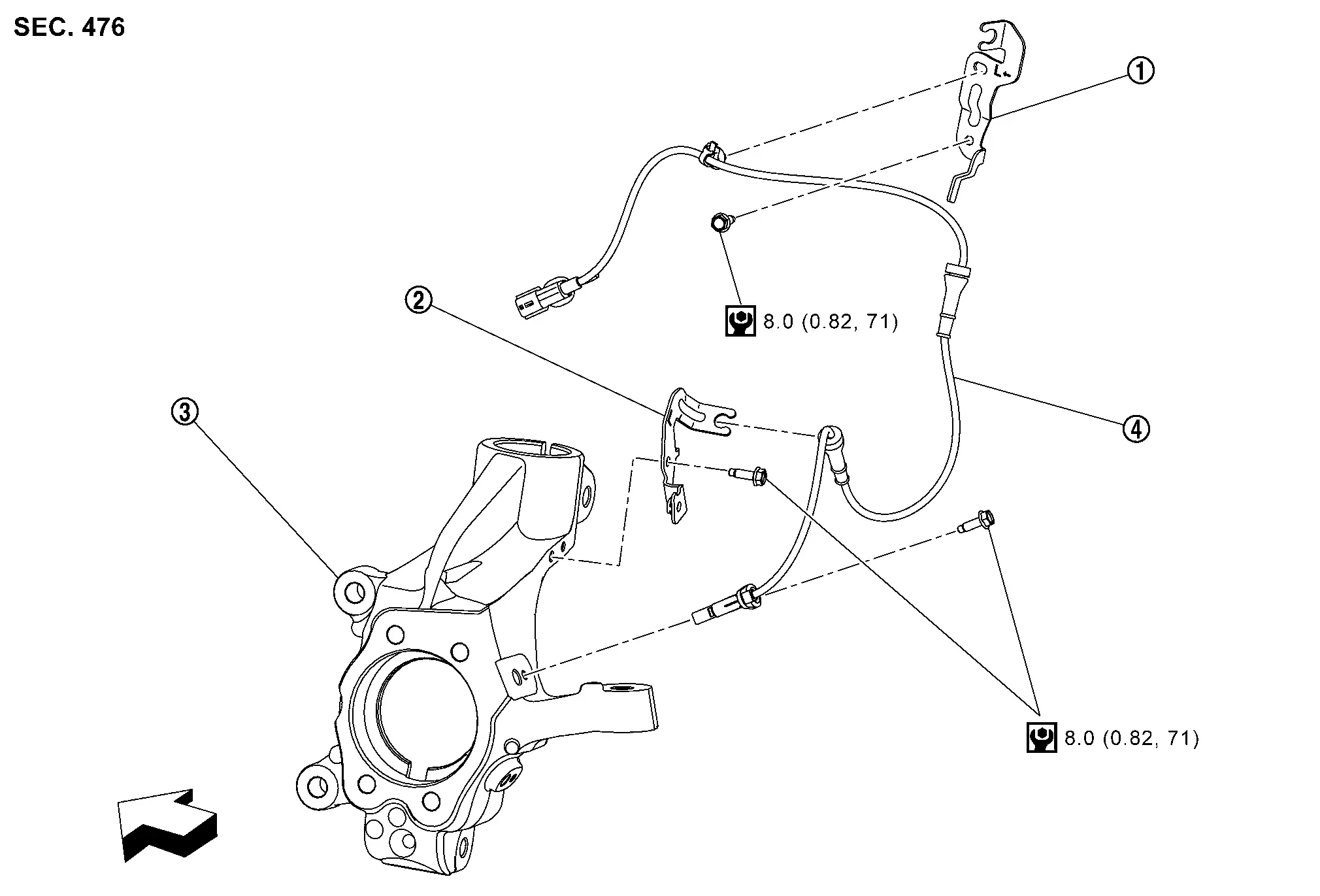
Bracket Bracket Steering knuckle
Front LH wheel sensor
: Nissan Ariya Vehicle front
: N·m (kg-m, in-lb)

FRONT WHEEL SENSOR : Removal & Installation

REMOVAL

Remove tires. Refer to Removal and Installation.

Remove fender protector (front). Refer to Removal and Installation.

Remove front wheel sensor harness connector.

Remove front wheel sensor mounting bolt and grommet , and then remove front wheel sensor from steering knuckle.
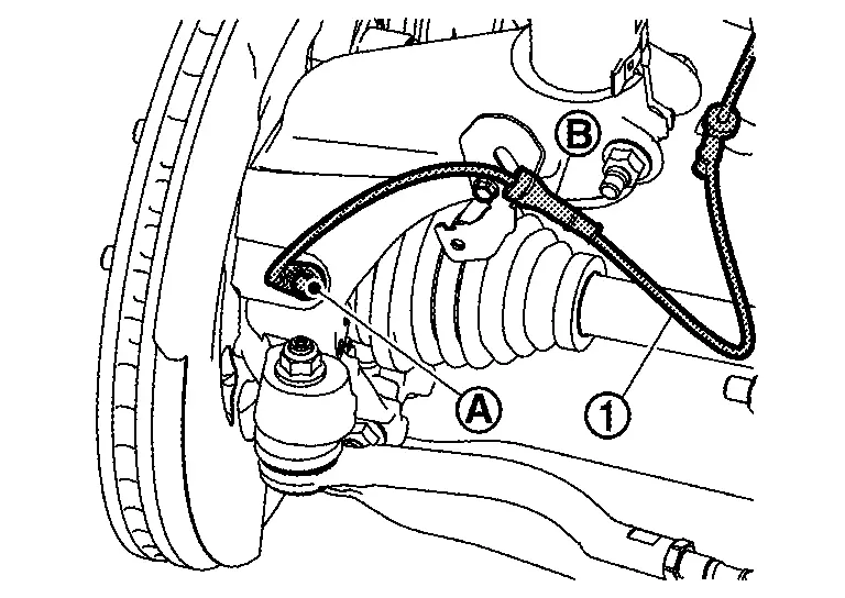
Remove grommet , harness clip and connector clip , and then remove front wheel sensor from Nissan Ariya vehicle.
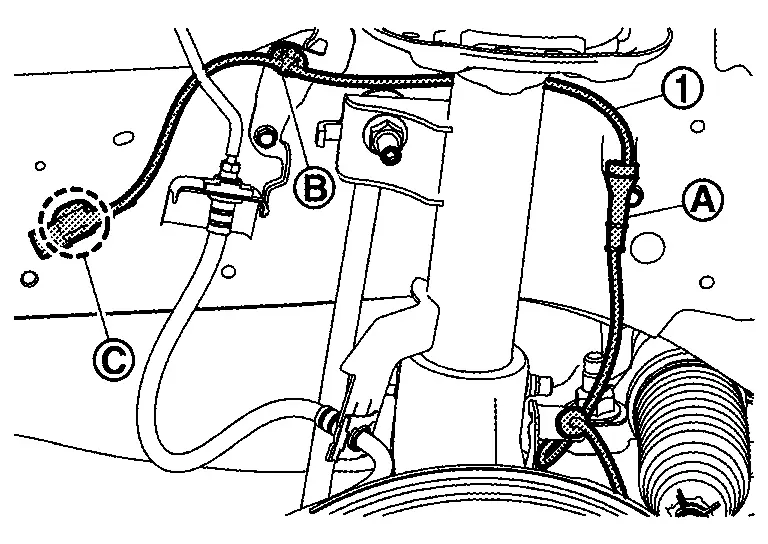
INSTALLATION

Note the following, and install in the reverse order of removal.

  • Check inner surface of front wheel sensor mounting hole and sensor rotor for foreign material like iron powder or damage. Install after cleaning, if there are foreign material like iron powder, or replace, if there is a malfunction.

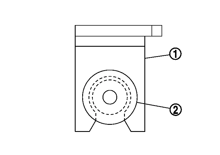
  • When front wheel sensor is installed by securely pushing its grommet into bracket , but never twist front wheel sensor harness. Check that grommet is fully inserted to bracket . Check front wheel sensor harness for twisting after installation.
Rear Wheel Sensor Nissan Ariya first Gen

REAR WHEEL SENSOR : Exploded View

Bracket Parking brake actuator harness LH and rear LH wheel sensor Axle housing
Rear brake caliper
: Nissan Ariya Vehicle front
: N·m (kg-m, ft-lb)
: N·m (kg-m, in-lb)

REAR WHEEL SENSOR : Removal & Installation

REMOVAL

Turn power switch ON.

Release the parking brake.

Turn power switch OFF.

Disconnect 12V battery negative terminal. Refer to Removal and Installation.

Remove rear tires. Refer to Removal and Installation.

Remove rear wheel house protector. Refer to Removal and Installation.

Remove Nissan Ariya vehicle side connectors of parking brake actuator harness and rear wheel sensor harness connector.

Remove parking brake actuator harness, rear wheel sensor harness mounting bolt , and harness clip and then remove parking brake actuator harness and rear wheel sensor harness from axle housing.
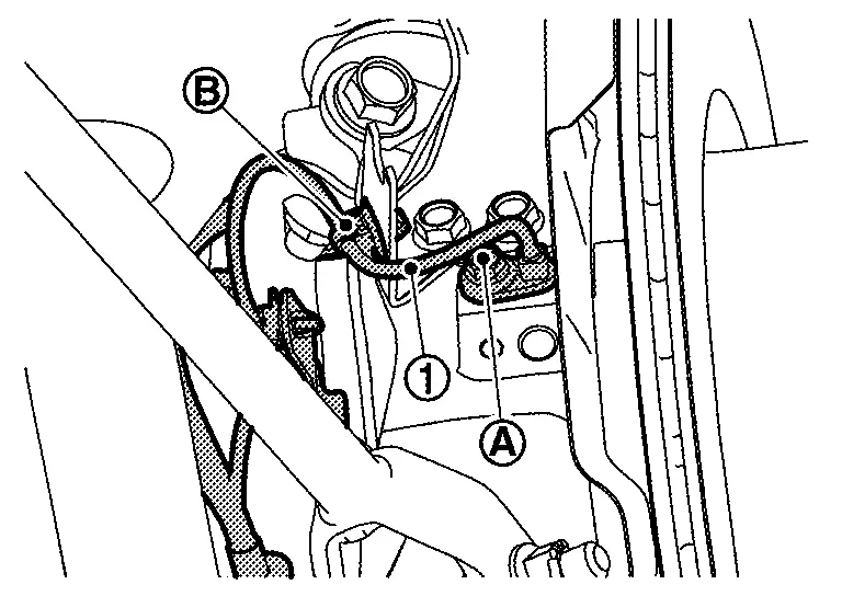
Remove bracket mounting bolt and the remove bracket .

Remove bracket mounting bolts and nuts and then remove bracket from Nissan Ariya vehicle.
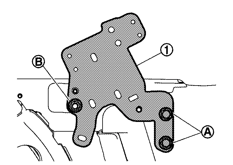
Remove height sensor connector clip and harness clip from bracket (left side only).

INSTALLATION

Note the following, and install in the reverse order of removal.

  • Check inner surface of rear wheel sensor mounting hole and sensor rotor for foreign material like iron powder or damage. Install after cleaning, if there are foreign materials like iron powder, or replace, if there is a malfunction.

  • When rear wheel sensor is installed by securely pushing its grommet into bracket , but never twist rear wheel sensor harness. Check that grommet is fully inserted to bracket. Check rear wheel sensor harness for twisting after installation.

Front Sensor Rotor Nissan Ariya SUV

FRONT SENSOR ROTOR : Removal & Installation

REMOVAL

Remove wheel bearing. Refer to Removal and Installation.

INSTALLATION

Install wheel bearing. Refer to Removal and Installation.

Abs Actuator and Electric Unit (control Unit) Nissan Ariya first Gen

ABS ACTUATOR AND ELECTRIC UNIT (CONTROL UNIT) : Exploded View
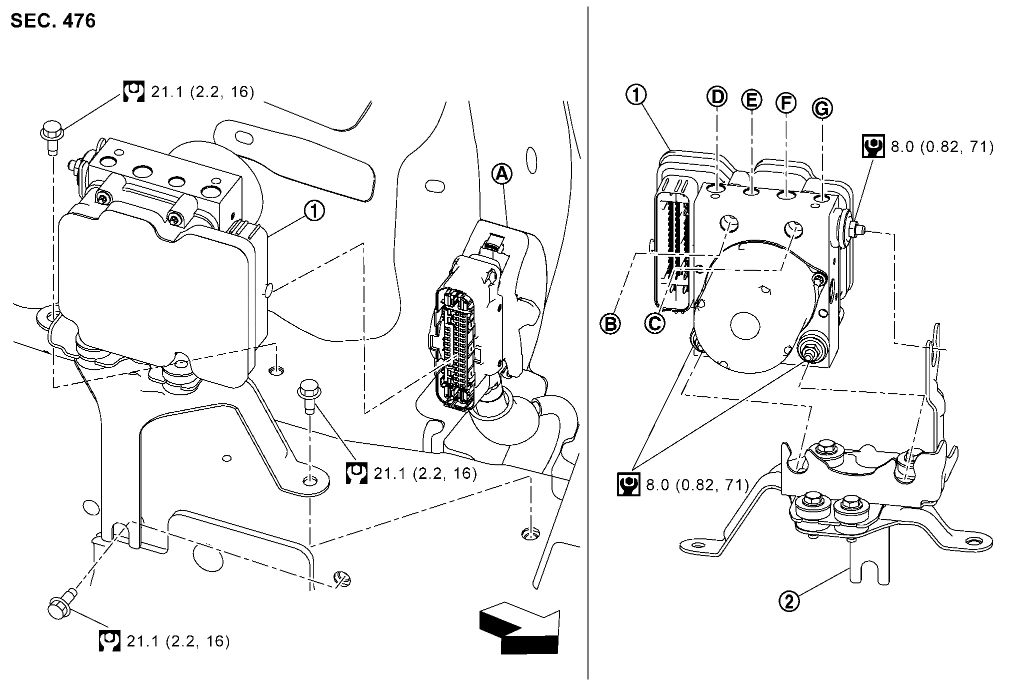
ABS actuator and electric unit (control unit) Bracket
ABS actuator and electric unit (control unit) harness connector To master cylinder secondary side. Refer to Exploded View. To master cylinder primary side. Refer to Exploded View.
To rear RH caliper. Refer to Exploded View. To front LH caliper. Refer to Exploded View. To front RH caliper. Refer to Exploded View.
To rear LH caliper. Refer to Exploded View.
: Nissan Ariya Vehicle front
: N·m (kg-m, ft-lb)
: N·m (kg-m, in-lb)

ABS ACTUATOR AND ELECTRIC UNIT (CONTROL UNIT) : Removal & Installation

REMOVAL

Disconnect 12V battery negative terminal. Refer to Removal and Installation.

Drain brake fluid. Refer to Draining.

Discharge A/C refrigerant gas. Refer to Refrigerant.

Drain coolant for high voltage system. Refer to Draining

Remove high voltage supply unit assembly.

Remove reservoir tank for sub radiator. Refer to Removal and Installation.

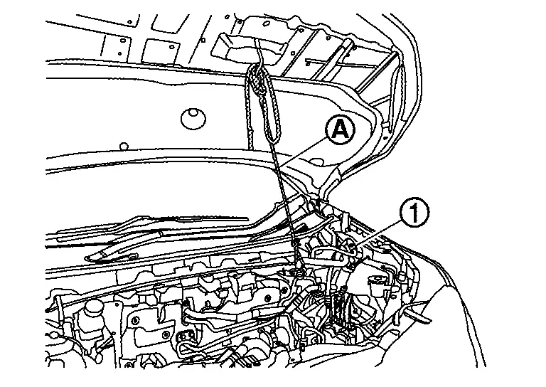
Remove mounting bolt of A/C pipe .

: Nissan Ariya Vehicle front

Hold A/C pipe with suitable rope to secure work space.
Remove ABS actuator and electric unit (control unit) harness connector according to the following procedure.
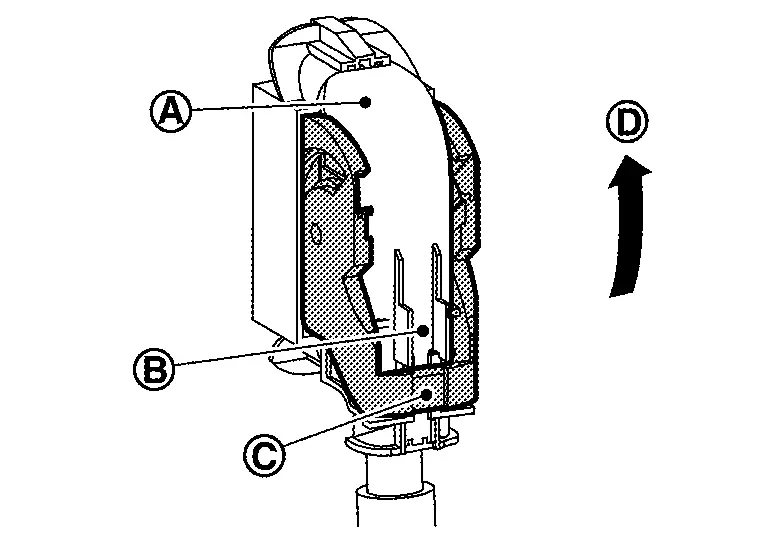
Push craw . Move lever in the direction until locked. Disconnect ABS actuator and electric unit (control unit) harness connector.

Loosen flare nut of brake tube using a flare nut wrench (B) and then remove brake tube from ABS actuator and electric unit (control unit) . Refer to Exploded View.
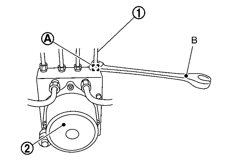
Remove ABS actuator and electric unit (control unit) and bracket.

Remove bracket and grommet from ABS actuator and electric unit (control unit).

INSTALLATION

Note the following, and install in the reverse order of removal.

  • When replacing with a new ABS actuator and electric unit (control unit), do not remove protector of the brake tube inlet hole until just before installing brake tube.

  • Never deform brake tube when installing ABS actuator and electric unit (control unit).

  • Temporarily tighten flare nut of brake tube by hand, and then using a flare nut wrench (B) tighten flare nut to the specified torque without damaging brake tube and flare nut. Refer to Exploded View.

    : ABS actuator and electric unit (control unit)

  • Never remove and install actuator by holding actuator harness.

  • Never apply excessive impact to actuator, such as by dropping it.

  • After installing ABS actuator and electric unit (control unit) harness connector , move lever in the direction and securely lock.
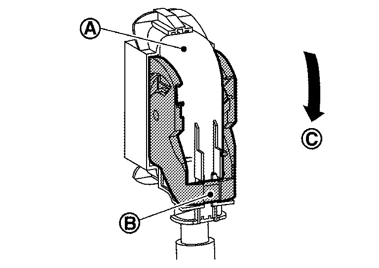
  • Make adjustments after installation. Refer to Adjustment.

ABS ACTUATOR AND ELECTRIC UNIT (CONTROL UNIT) : Adjustment

ADJUSTMENT AFTER INSTALLATION

  • When ABS actuator and electric unit (control unit) are replaced, perform the following procedure.

    • Procedure of ABS actuator and electric unit (control unit): Refer to Work Procedure.

    • Brake piping air bleeding: Refer to Air Bleeding.

  • When ABS actuator and electric unit (control unit) are removed and installed, perform the following procedure.

    • G sensor calibration: Refer to Work Procedure.

    • Brake piping air bleeding: Refer to Air Bleeding.

Steering Angle Sensor Nissan Ariya 1st generation

STEERING ANGLE SENSOR : Removal & Installation

REMOVAL

Remove spiral cable assembly. Refer to Removal & Installation.

Unlock claws and then remove steering angle sensor from spiral cable .
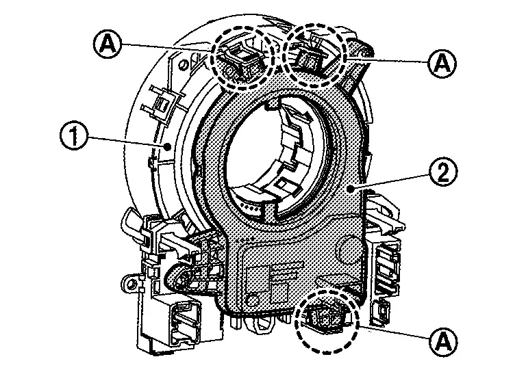
INSTALLATION

Note the following, and install in the reverse order of removal.