Component Parts

In this manual: Component Parts
How to Use This Manual — 1Precautions — 1Preparation — 1Vehicle Information — 1Basic Inspection — 1Preparation. Commercial Service Tools Or/and Repair Part — 1Description — 1Component Parts — 1System — 1Diagnosis System (vcm) — 1Ecu Diagnosis Information. Vcm — 1Ev Control System — 1Ev/hev (vcm) — 1Component Parts /circuit Diagnosis — 1Ev Control System — 1Periodic Maintenance. Ev System Warning Lamp — 1Removal and Installation. Vcm — 1Traction Motor System :: Front Traction Motor — 1Preparation — 1Description — 4Basic Inspection — 2Dtc Diagnosis — 2Component Parts /circuit Diagnosis — 1Traction Motor System :: Rear Traction Motor — 1Description — 4Basic Inspection — 2Dtc Diagnosis — 2Component Parts /circuit Diagnosis — 1Removal and Installation — 1Ev Battery System :: 66kwh Li-Ion Battery — 1Description — 4Basic Inspection — 2Dtc Diagnosis — 2Component Parts /circuit Diagnosis — 1Removal and Installation — 1Disassembly and Assembly — 2Service Data — 1Ev Battery System :: 91kwh Li-Ion Battery — 1Description — 4Basic Inspection — 2Dtc Diagnosis — 2Component Parts /circuit Diagnosis — 1Removal and Installation — 1Disassembly and Assembly — 1Service Data — 2Preparation. Vehicle Charging System — 1Vehicle Charging System :: Description — 1Component Parts — 2System — 1Diagnosis System (on-Board Charger) — 1Diagnosis System (dc/dc Converter) — 1Ecu Diagnosis Information — 1Vehicle Charging System — 1Charger/pd Module (on-Board Charger) — 1Cplc (cplc) — 1Dcdc (dc/dc Converter) — 1Component Parts/circuit Diagnosis — 1Symptom Diagnosis — 1Evse Inspection — 1Periodic Maintenance — 1Removal and Installation — 1Disassembly and Assembly — 1Preparation. High Voltage Cooling System — 1Description — 1Symptom Diagnosis. Overheating Cause Analysis — 1Periodic Maintenance — 1Coolant — 1Removal and Installation — 1Radiator — 1Service Data — 1Removal and Installation. Accelerator Control System — 1Reduction Gear: Re1f62a — 1Removal and Installation — 1Transaxle & Transmission :: Electric Shift — 1Description — 3Basic Inspection — 2Dtc Diagnosis — 2Component Parts /circuit Diagnosis — 1Removal and Installation — 1Rear Final Drive: Rn1r62a — 1Removal and Installation — 1Preparation. Front Axle System — 1Symptom Diagnosis. Noise, Vibration and Harshness (nvh) Troubleshooting — 1Periodic Maintenance — 1Removal and Installation — 1Service Data. Front Drive Shaft — 12wd — 14wd — 1Periodic Maintenance — 1Removal and Installation — 1Preparation. Front Suspension System — 1Symptom Diagnosis. Noise, Vibration and Harshness (nvh) Troubleshooting — 1Periodic Maintenance — 1Removal and Installation — 1Service Data — 1Symptom Diagnosis. Noise, Vibration and Harshness (nvh) Troubleshooting — 1Periodic Maintenance — 1Removal and Installation — 1Service Data — 1Preparation. Road Wheels & Tires System — 1Description — 1System — 1Ecu Diagnosis Information. Bcm (body Control Module) — 1Tpms — 1Dtc/circuit Diagnosis — 1Symptom Diagnosis — 1Periodic Maintenance. Road Wheels & Tires — 1Removal and Installation — 1Service Data — 1Preparation. Brake System — 1System Description — 1Component Parts — 1Ecu Diagnosis Information. Electrically-Driven Intelligent Brake Unit — 1Basic Inspection — 1Dtc/circuit Diagnosis — 1Symptom Diagnosis — 1Periodic Maintenance — 1Removal and Installation — 1Service Data — 1Preparation. Parking Brake System — 1System Description — 1Component Parts — 1System — 1Ecu Diagnosis Information. Abs Actuator and Electric Unit (control Unit) — 1Basic Inspection. Diagnosis and Repair Work Flow — 1Component Parts /circuit Diagnosis — 1Symptom Diagnosis — 1Removal and Installation — 1Brake Control System :: With Vdc — 1System Description — 3Basic Inspection — 2Dtc/circuit Diagnosis — 1Symptom Diagnosis — 2Removal and Installation — 1Brake Control System :: Automatic Brake Hold — 1System Description — 3Component Parts /circuit Diagnosis — 1Removal and Installation — 1Brake Control System :: E-Step — 1System Description — 3Removal and Installation — 1System Description — 1Ecu Diagnosis Information — 1Basic Inspection — 1Symptom Diagnosis — 1Rear Automatic Braking — 1System Description — 1Basic Inspection — 1Preparation. Steering System — 1System Description — 1Component Parts — 1Basic Inspection — 1Dtc/circuit Diagnosis — 1Symptom Diagnosis — 1Periodic Maintenance. Steering Wheel — 1Removal and Installation — 1Service Data — 1System Description — 1Component Parts — 1Steering Control System — 1Ecu Diagnosis Information. Power Steering Control Module — 1Dtc/circuit Diagnosis — 1Component Parts /circuit Diagnosis — 1Symptom Diagnosis — 1Removal and Installation. Power Steering Control Module — 1System Description — 1Removal and Installation — 1System Description — 1System — 1Basic Inspection. Diagnosis and Repair Work Flow — 1Dtc/circuit Diagnosis — 1Symptom Diagnosis — 1Component Parts — 1Basic Inspection — 1Removal and Installation — 1System Description — 1System — 1Ecu Diagnosis Information. Air Bag Diagnosis Sensor Unit — 1Basic Inspection — 1Dtc/circuit Diagnosis — 1Symptom Diagnosis — 1System Description. Description. Ventilation System — 1Removal and Installation — 1Preparation. Preparation — 1System Description — 1Basic Inspection — 1Symptom Diagnosis — 1Removal and Installation — 1Electric Compressor — 1Cooler Pipe and Hose — 1A/c Unit Assembly Cover — 1A/c Unit Assembly — 1Heater & Air Conditioning Control System :: Automatic Air Conditioning — 1System Description — 1Ecu Diagnosis Information — 1Basic Inspection — 2Dtc Diagnosis — 1Symptom Diagnosis — 1Removal and Installation — 2Preparation. Preparation — 1Symptom Diagnosis. Squeak and Rattle Trouble Diagnoses — 1Removal and Installation — 1Preparation. Instrument Panel — 1Component Parts — 1System — 1Ecu Diagnosis Information. Flexible Center Storage Control Module — 1Basic Inspection. Diagnosis and Repair Work Flow — 1Dtc/circuit Diagnosis — 1Symptom Diagnosis — 1Removal and Installation — 1Preparation. Preparation — 1Component Parts — 1System — 1Ecu Diagnosis Information. Driver Lumbar Support Control Module — 1Basic Inspection. Diagnosis and Repair Work Flow — 1Dtc/circuit Diagnosis — 1Symptom Diagnosis — 1Removal and Installation — 1System Description — 1System — 1Ecu Diagnosis Information — 1Basic Inspection — 1Dtc/circuit Diagnosis — 1Symptom Diagnosis — 1Manual Function Does Not Operate — 1Memory Function Does Not Operate — 1Removal and Installation — 1Preparation. Preparation — 1System Description — 1System (intelligent Key System) — 1Diagnosis System (bcm) — 1Ecu Diagnosis Information — 1Basic Inspection — 1Dtc/circuit Diagnosis — 1U2141-87 Can Comm Circuit — 1Power Supply and Ground Circuit — 1Symptom Diagnosis — 1Automatic Back Door Operation Does Not Operate — 1Back Door Does Not Open — 1Door Does Not Lock/unlock with Door Lock and Unlock Switch — 1Removal and Installation — 1Hood — 1Radiator Core Support — 1Charge Port Lid — 1Front Fender — 1Front Door — 1Rear Door — 1Back Door — 1Hood Lock — 1Front Door Lock — 1Rear Door Lock — 1Back Door Lock — 1Outside Key Antenna — 1System Description — 1System — 1Ecu Diagnosis Information. Inverter (front), Inverter (rear), Bcm, Intelligent Key Unit — 1Basic Inspection — 1Dtc/circuit Diagnosis — 1Symptom Diagnosis — 1Preparation — 1Symptom Diagnosis. Squeak and Rattle Trouble Diagnoses — 1Removal and Installation — 1System Description — 1Ecu Diagnosis Information — 1Basic Inspection — 1Dtc/circuit Diagnosis — 1Power Supply and Ground Circuit — 1Symptom Diagnosis — 1Front Passenger Side Power Window Does Not Operate — 1Rear Lh Side Power Window Does Not Operate — 1Rear Rh Side Power Window Does Not Operate — 1Removal and Installation. Power Window Main Switch — 1Preparation. Preparation — 1System Description — 1Ecu Diagnosis Information — 1Basic Inspection — 1Dtc/circuit Diagnosis — 1Power Supply and Ground Circuit — 1Sunroof Switch Assembly — 1Symptom Diagnosis — 1Auto Operation Does Not Operate — 1Removal and Installation — 1Preparation — 1Description — 1Symptom Diagnosis. Squeak and Rattle Trouble Diagnoses — 1Removal and Installation — 1Service Information — 6Repair Information — 1Precaution — 1Preparation — 1Removal and Installation — 1Service Data — 1Preparation. Preparation — 1Component Parts — 1System — 1Ecu Diagnosis Information — 1Wiring Diagram. Door Mirror — 1Basic Inspection. Diagnosis and Repair Work Flow — 1Dtc/circuit Diagnosis — 1Power Supply and Ground Circuit — 1Symptom Diagnosis — 1Removal and Installation — 1Exterior Lighting System :: Led Headlamp — 1System Description — 3Basic Inspection — 1Dtc/circuit Diagnosis — 1Symptom Diagnosis — 1Periodic Maintenance — 1Removal and Installation — 1System Description — 1System — 1Diagnosis System (bcm) — 1Ecu Diagnosis Information. Bcm, Intelligent Key Unit — 1Basic Inspection. Diagnosis and Repair Work Flow — 1Dtc/circuit Diagnosis — 1Symptom Diagnosis. Interior Lighting System Symptom — 1Removal and Installation — 1Service Data. Bulb Specifications — 1System Description — 1System — 1Ecu Diagnosis Information. Bcm, Ipdm E/r — 1Basic Inspection. Diagnosis and Repair Work Flow — 1Dtc/circuit Diagnosis — 1Symptom Diagnosis — 1Removal and Installation — 1System Description — 1Ecu Diagnosis Information. Bcm — 1Basic Inspection. Diagnosis and Repair Work Flow — 1Dtc/circuit Diagnosis — 1Symptom Diagnosis — 1Removal and Installation — 1Preparation. Preparation — 1Removal and Installation. Horn — 1Preparation. Commercial Service Tools Or/and Repair Part — 1System Description — 1Component Parts — 1Ecu Diagnosis Information. Approaching Vehicle Sound for Pedestrians (vsp) Control Unit — 1Approaching Vehicle Sound for Pedestrians (vsp) — 1Vsp [approaching Vehicle Sound for Pedestrians (vsp) Control Unit] — 1Approaching Vehicle Sound for Pedestrians (vsp) System — 1Removal and Installation — 1Removal and Installation — 1Wireless Charger — 1System Description — 1Basic Inspection — 1Dtc/circuit Diagnosis — 1Removal and Installation — 1Component Parts — 1System — 1Diagnosis System (bcm) — 1Ecu Diagnosis Information. Bcm — 1Basic Inspection — 1Dtc/circuit Diagnosis — 1Symptom Diagnosis — 1Removal and Installation — 1Can Fundamental — 1Description — 1Trouble Diagnosis — 1Can (controller Area Network) — 1Description — 1
5steps
~30min
2/5difficulty
Done 0 of 5
  • Vehicle Charging System
  • Charge Connector Lock Actuator
  • Charge Port
  • Charge Port Light
  • Charging Status Indicator
  • Cplc
  • Dc/dc Converter
  • Evse
  • High Voltage Junction Box
  • High Voltage Warning Label
  • Immediate Charging Switch
  • On-Board Charger

Vehicle Charging System Nissan Ariya

Component Parts Location

Combination meter Charging status indicator Li-ion battery
EVSE Charge connector lock actuator Charge port lid actuator
Charge port light Charge port CPLC
VCM On-board charger DC/DC converter
High voltage junction box Immediate charging switch
Nissan Ariya Vehicle right side Under the front floor spacer High voltage power delivery ASSY
Instrument lower panel LH

Charge Connector Lock Actuator Nissan Ariya 1st generation

Component Description

FUNCTIONS WITHIN THE SYSTEM

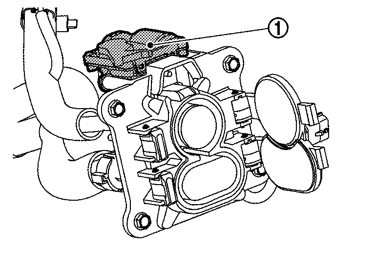
Charge connector lock actuator locks charge connector by lock pin, when charge connector is connected to normal charge port during normal charge. Refer to System Description.
INDIVIDUAL OPERATION

The charge connector is locked by inserting a lock pin of the charge connector lock actuator into the tip of normal charge connector.

Operation

Lock pin is operated to Lock/Unlock position by operation request signal from VCM.

PARTS LOCATION

Charge connector lock actuator is installed to top of charge port.

Refer to Specifications.

Charge Port Nissan Ariya 1st generation

Component Description

FUNCTIONS WITHIN THE SYSTEM

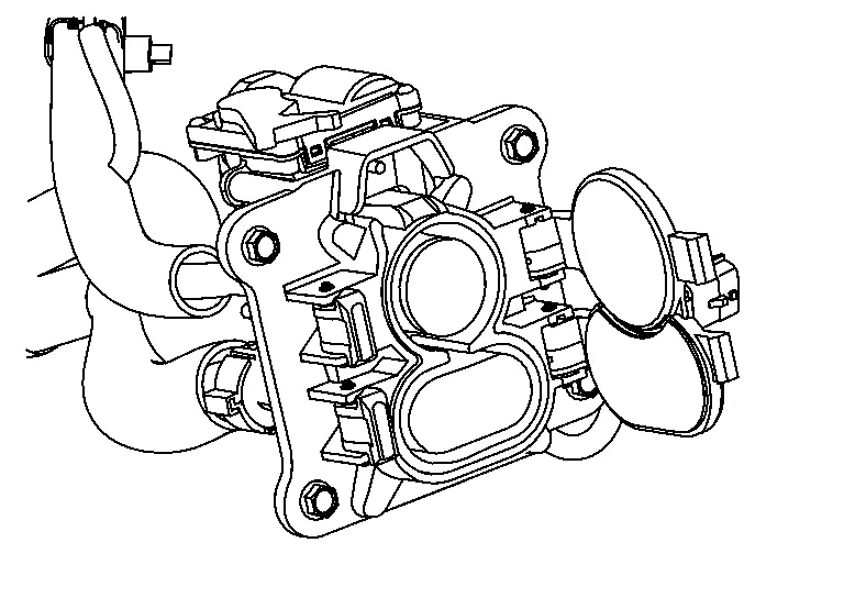
The quick charge port is installed to the side of vehicle. At normal charge, it connects EVSE (charge cable) or mode 3 cable charge connector to send high voltage current to the on-board charger. At quick charge, it connects the connector of the quick charger and send high voltage current to the high voltage battery.
INDIVIDUAL OPERATION

The charge port is installed to the side of vehicle. At normal charge, it connects EVSE (charge cable) or mode 3 cable charge connector to send high voltage current to the on-board charger. At quick charge, it connects the connector of the quick charger and send high voltage current to the high voltage battery.

Operation
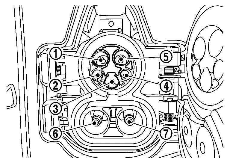
High voltage
EVSE communication
Ground
EVSE connection signal
High voltage
High voltage (Quick Charge)

Connection detection circuit is provided to detect connection (half lock) status with charge connector

PARTS LOCATION

Charge port is installed into charge port lid of side of vehicle.

Refer to Specifications.

Charge Port Light Nissan Ariya: FE0

Component Description

FUNCTIONS WITHIN THE SYSTEM

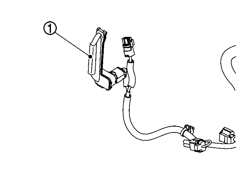
The charge port light lights up inside in charge port lid to support the charge connector connection.
INDIVIDUAL OPERATION

Charge port light :LED

Operation

Charge port light is turned ON/OFF based on signal from VCM

PARTS LOCATION

Charge port light is installed into charge port lid.

Refer to Specifications.

Charging Status Indicator Nissan Ariya 1st generation

Component Description

FUNCTIONS WITHIN THE SYSTEM

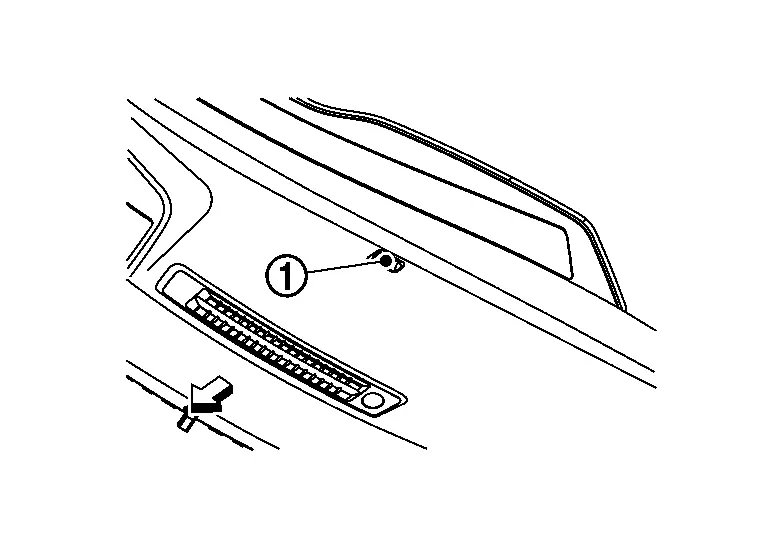
Charging status indicator changing one indicator into 3 colors to display charge status of the Li-ion battery.
: Charging status indicator
: Nissan Ariya Vehicle front

INDIVIDUAL OPERATION

Charging station communication module turns ON/OFF/ BLINK according to control signal from VCM.

Operation

Charging status indicator is operated as follows;

Indicator illuminating pattern
Nissan Ariya Vehicle conditionIndicator lampIlluminating (blinking) timeCondition
Upon connecting charge connector
Blue OFF after 3 sec. maximum
During charge
Blue Battery level: 75-100%
Battery level: 50-74%
Battery level: 25-49%
Battery level: 0-24%
Full charge completed
Blue
Receiving timer charge
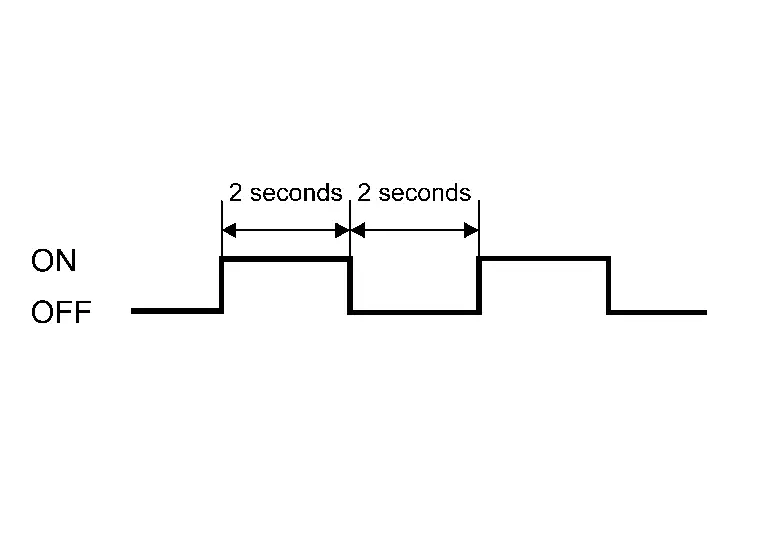
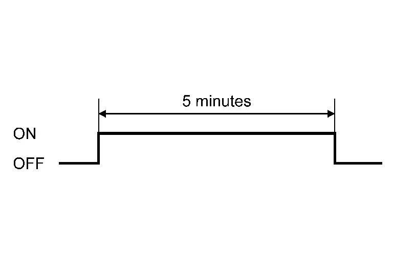
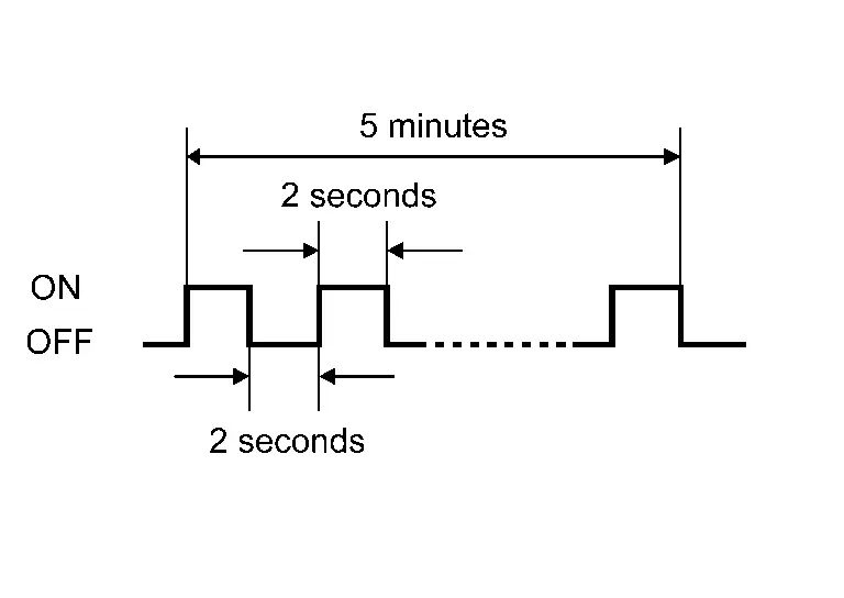
Green ON-OFF repeats for 5min.
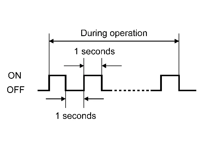
During the following conditions while operating high electric system; *12 battery automatic charge *Timer/Remote(before getting in) A/C operates *Software updates *Upon disconnecting plug from output *While V2H discharges
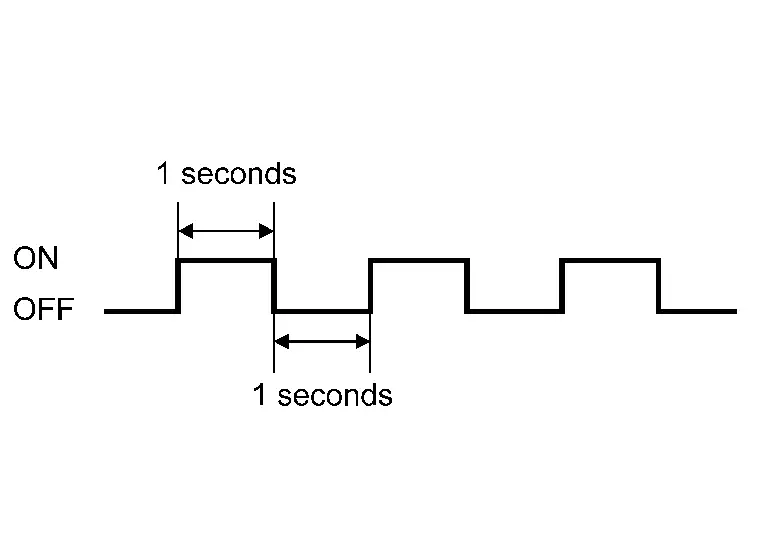
Green Blinks during operation
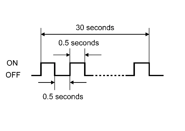
Normal charge connector warning (half lock )
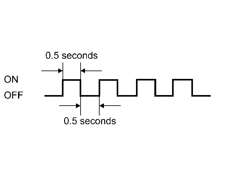
Red Blinks for 30 sec.

PARTS LOCATION

Charge status indicator is installed to upper side of instrument panel.

Refer to Specifications.

Cplc Nissan Ariya: FE0

Component Description

FUNCTIONS WITHIN THE SYSTEM

CPLC converts signals of quick charge communication between charger and vehicle.
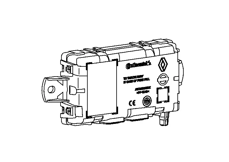
INDIVIDUAL OPERATION

CPLC is ECU that converts signals of quick charge communication between charger and vehicle during quick charge.

Operation

CPLC is ECU that converts signals of quick charge communication between charger and vehicle during quick charge via CAN communication.

PARTS LOCATION

CPLC is installed to under front floor spacer near passenger foot.

Dc/dc Converter Nissan Ariya SUV

Component Description

FUNCTIONS WITHIN THE SYSTEM

  • High DC voltage from Li-ion battery is stepped down to DC 14 V approximately to charge 12V battery.

  • Output voltage is changed by the signal from VCM to supply the optimum voltage for Nissan Ariya vehicle condition.
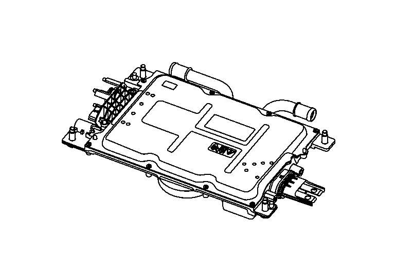
INDIVIDUAL OPERATION

DC/DC converter steps down power from Li-ion battery to optimum voltage to supply power to vehicle.

Operation

High DC voltage of Li-ion battery is stteped down to DC 14 V approximately

PARTS LOCATION

DC/DC converter is installed under high voltage supply unit in motor room.

High Voltage Junction Box Nissan Ariya 1st generation

Component Description

FUNCTIONS WITHIN THE SYSTEM

High voltage junction box distributes high voltage power supply to each component parts, and has a built-in temperature sensor to transmit signal to VCM
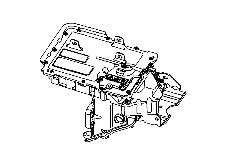
INDIVIDUAL OPERATION

High voltage junction box sends high voltage power supply from Li-ion batter to the connected high voltage component parts such as DC/DC converter, electric compressor, etc..

Operation

High voltage power supply from Li-ion battery is distributed.

PARTS LOCATION

High voltage junction box is installed to high voltage supply unit ASSY on the left side of vehicle in the motor room.

High Voltage Warning Label Nissan Ariya 2026

Component Description

PARTS LOCATION

High voltage warning label is attached to upper front of high voltage junction box.
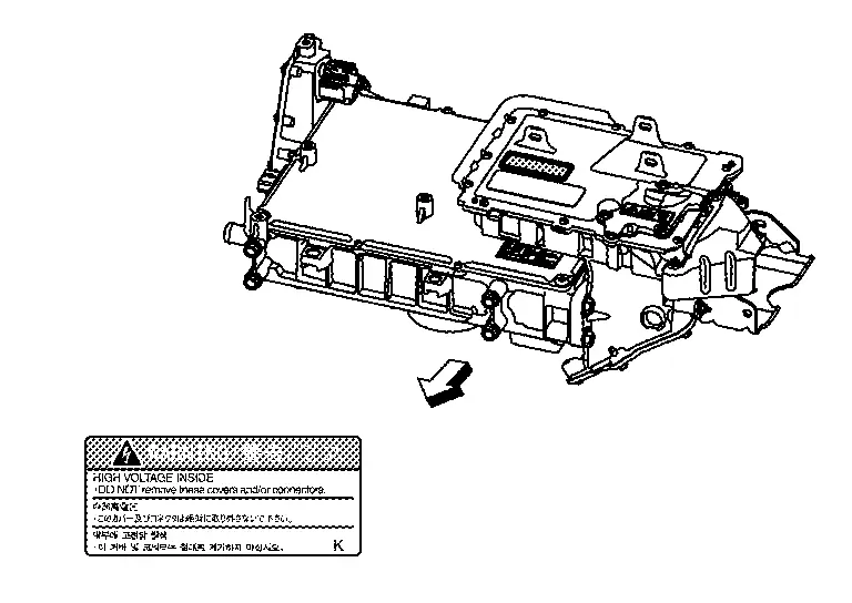
:Nissan Ariya Vehicle front

Immediate Charging Switch Nissan Ariya 2026

Component Description

FUNCTIONS WITHIN THE SYSTEM

Charge can start immediately by operating immediate charging switch when timer charge is set.

INDIVIDUAL FUNCTIONS WITHIN THE SYSTEM

The switch inputs immediate charging switch status to VCM.

INDIVIDUAL OPERATION

Momentary switch is adopted, and voltage is changed to 0 V and 5 V by turning the switch ON and OFF.

VCM reads the switch status according to potential change.

PARTS LOCATION

Immediate charging switch is installed to instrument lower panel.

Refer to Specifications.

On-Board Charger Nissan Ariya first Gen

Component Description

FUNCTIONS WITHIN THE SYSTEM

On-board charger converts external AC power supply to DC power supply (300 V- 430 V) and charges Li-ion battery.
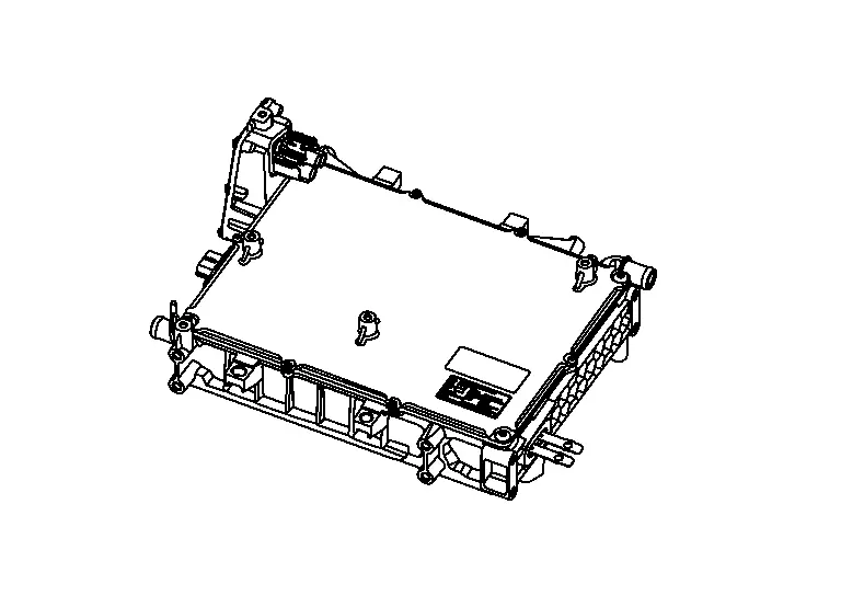
INDIVIDUAL OPERATION

PFC circuit is adopted for on-board charger to improve charge efficiency and amount of charge, and to extend life of Li-ion battery.

Operation

  1. AC power input from external power supply is rectified to DC power supply by rectifier circuit 1.

  2. Rectified DC power supply is boosted at the same time as the power factor is improved by PFC circuit.

  3. Boosted DC power supply is converted to AC power supply again by inverter.

  4. AC power supply from inverter is converted voltage by insulated transformer and rectified to high voltage DC power by rectifier circuit 2.

  5. Rectified high voltage DC power is output from output circuit.

PARTS LOCATION

On-board charger is installed above the traction motor in the motor room as high voltage supply unit assembly.

Refer to Specifications.