Ecu Diagnosis Information
- Bcm
- Intelligent Key Unit
- Automatic Back Door Control Unit
- Hands Free Sensor Control Unit
Bcm Nissan Ariya 1st generation
List of ECU Reference
| ECU | Reference |
|---|---|
| BCM | Reference Value |
| Fail-safe | |
| DTC Inspection Priority Chart | |
| DTC Index |
Intelligent Key Unit Nissan Ariya 2023
Reference Value
VALUES ON THE DIAGNOSIS TOOL
| Monitor Item | Condition | Value/Status |
|---|---|---|
| Intelligent Key unit blank status | Intelligent Key unit is registered | OFF |
| Intelligent Key unit is not registered (blank status) | ON | |
| Intelligent Key unit power supply status | Intelligent Key unit power supply normally | OFF |
Intelligent Key unit power supply malfunction |
ON | |
| Key ID1 | Which touching the one touch sensor carrying the Intelligent Key #1 | ON |
| Other than above | OFF | |
| Key ID2 | Which touching the one touch sensor carrying the Intelligent Key #2 | ON |
| Other than above | OFF | |
| Key ID3 | Which touching the one touch sensor carrying the Intelligent Key #3 | ON |
| Other than above | OFF | |
| Key ID4 | Which touching the one touch sensor carrying the Intelligent Key #4 | ON |
| Other than above | OFF | |
| Battery voltage | Power switch ON | 10 – 16 V |
| Ignition ON (IPDM E/R) | Other than power switch ON | OFF |
| Power switch ON | ON | |
| Nissan Ariya Vehicle speed (ABS) | While driving | Equivalent to speedometer reading |
| Nissan Ariya Vehicle speed (meter) | While driving | Equivalent to speedometer reading |
| Total distance | While driving | Indicates total Nissan Ariya vehicle distance |
| Keyfob button1 | Other than below | OFF |
| UNLOCK button is pressed | ON | |
| Keyfob button2 | Other than below | OFF |
| LOCK button is pressed | ON | |
| Keyfob button3 | Other than below | OFF |
| PANIC button is pressed | ON | |
| Keyfob button4 | Other than below | OFF |
| POWER BACK DOOR button is pressed | ON | |
| Back door/trunk opener switch | When back door opener switch circuit is malfunction | Malfunction |
| When back door opener switch is not pressed | OFF | |
| When back door opener switch is pressed | ON | |
| Key ID (last) | When any Intelligent Key button is pressed | 1,2,3,4 |
| Keyfob#1 cabin area | Other than below | OFF |
| When Intelligent Key #1 is in cabin area, touch the one touch sensor carrying other Intelligent Key | ON | |
| Keyfob#1 undefined area | When Intelligent Key #1 is detected by multiple inside/ outside key antenna | OFF |
| When Intelligent Key #1 is out of range of the defined Intelligent Key unit area | ON | |
| Keyfob#1 rear bumper area | Other than below | OFF |
| When Intelligent Key #1 is in rear bumper area, touch the one touch sensor carrying other Intelligent Key | ON | |
| Keyfob#2 cabin area | Other than below | OFF |
| When Intelligent Key #2 is in cabin area, touch the one touch sensor carrying other Intelligent Key | ON | |
| Keyfob#2 undefined area | When Intelligent Key #2 is detected by multiple inside/ outside key antenna | OFF |
| When Intelligent Key #2 is out of range of the defined Intelligent Key unit area | ON | |
| Keyfob#2 rear bumper area | Other than below | OFF |
| When Intelligent Key #2 is in rear bumper area, touch the one touch sensor carrying other Intelligent Key | ON | |
| Keyfob#3 cabin area | Other than below | OFF |
| When Intelligent Key #3 is in cabin area, touch the one touch sensor carrying other Intelligent Key | ON | |
| Keyfob#3 undefined area | When Intelligent Key #3 is detected by multiple inside/ outside key antenna | OFF |
| When Intelligent Key #3 is out of range of the defined Intelligent Key unit area | ON | |
| Keyfob#3 rear bumper area | Other than below | OFF |
| When Intelligent Key #3 is in rear bumper area, touch the one touch sensor carrying other Intelligent Key | ON | |
| Keyfob#4 cabin area | Other than below | OFF |
| When Intelligent Key #4 is in cabin area, touch the one touch sensor carrying other Intelligent Key | ON | |
| Keyfob#4 undefined area | When Intelligent Key #4 is detected by multiple inside/ outside key antenna | OFF |
| When Intelligent Key #4 is out of range of the defined Intelligent Key unit area | ON | |
| Keyfob#4 rear bumper area | Other than below | OFF |
| When Intelligent Key #4 is in rear bumper area, touch the one touch sensor carrying other Intelligent Key | ON | |
| Keyfob button5 | OFF | |
| Keyfob operation | Intelligent Key button is not pressed | OFF |
| UNLOCK button is pressed | Unlock | |
| LOCK button is pressed | Lock | |
| POWER BACK DOOR button is pressed | Trunk/back door | |
| PANIC | ||
| Automatic sliding door (RH) | ||
| Automatic sliding door (LH) | ||
| Light | ||
| Engine starter | ||
| Roof | ||
| Push switch | Power switch (push-switch) is pressed | ON |
| Power switch (push-switch) is not pressed | OFF | |
| Request switch (Front right) | OFF | |
| Request switch (Front left) | OFF | |
| Request switch (Back Door) | When back door request switch is not pressed | OFF |
| When back door request switch is pressed | ON | |
| Registration Key ID status | Intelligent Key is not registered | OFF |
| Intelligent Key is registered | ON | |
| Keyfob#1 outside area (LH) | When Intelligent Key #1 is out of range of outside key antenna (rear door LH) | OFF |
| When Intelligent Key #1 is in range of outside key antenna (rear door LH) | ON | |
| Keyfob#1 outside area (RH) | When Intelligent Key #1 is out of range of outside key antenna (rear door RH) | OFF |
| When Intelligent Key #1 is in range of outside key antenna (rear door RH) | ON | |
| Keyfob#2 outside area (LH) | When Intelligent Key #2 is out of range of outside key antenna (rear door LH) | OFF |
| When Intelligent Key #2 is in range of outside key antenna (rear door LH) | ON | |
| Keyfob#2 outside area (RH) | When Intelligent Key #2 is out of range of outside key antenna (rear door RH) | OFF |
| When Intelligent Key #2 is in range of outside key antenna (rear door RH) | ON | |
| Keyfob#3 outside area (LH) | When Intelligent Key #3 is out of range of outside key antenna (rear door LH) | OFF |
| When Intelligent Key #3 is in range of outside key antenna (rear door LH) | ON | |
| Keyfob#3 outside area (RH) | When Intelligent Key #3 is out of range of outside key antenna (rear door RH) | OFF |
| When Intelligent Key #3 is in range of outside key antenna (rear door RH) | ON | |
| Keyfob#4 outside area (LH) | When Intelligent Key #4 is out of range of outside key antenna (rear door LH) | OFF |
| When Intelligent Key #4 is in range of outside key antenna (rear door LH) | ON | |
| Keyfob#4 outside area (RH) | When Intelligent Key #4 is out of range of outside key antenna (rear door RH) | OFF |
| When Intelligent Key #4 is in range of outside key antenna (rear door RH) | ON | |
| Keyfob#1 battery low | Intelligent Key unit detects low battery in Intelligent Key #1 | 0 – 6 |
| Keyfob#2 battery low | Intelligent Key unit detects low battery in Intelligent Key #2 | 0 – 6 |
| Keyfob#3 battery low | Intelligent Key unit detects low battery in Intelligent Key #3 | 0 – 6 |
| Keyfob#4 battery low | Intelligent Key unit detects low battery in Intelligent Key #4 | 0 – 6 |
| Battery voltage (IPDM E/R) | Power switch ON | 10 – 18 V |
| Nissan Ariya Vehicle condition | Intelligent Key unit status is low power consumption mode (sleep mode) | Sleep |
| Intelligent Key unit status is low power consumption mode (normal mode) | Wake up | |
| Power supply position is "OFF" | OFF | |
| Power supply position is "ACC" | ACC | |
| Power supply position is "IGN ON" | IGN ON | |
| Power supply position is "Cranking" | Cranking | |
| Power supply position is "Running" | Running | |
| stop/start | ||
| Stalled | ||
| Steering lock unit power output | OFF | |
| Request switch (Rear right) | OFF | |
| Request switch (Rear left) | OFF |
TERMINAL LAYOUT

PHYSICAL VALUES
Terminal No. (Wire color) | Description | Condition | Value (Approx.) | |||
|---|---|---|---|---|---|---|
| Signal name | Input/ Output | |||||
| (+) | (-) | |||||
1 (LA/SB) |
Ground | Battery power supply | Input | — | Battery voltage | |
3 (G) |
Ground | Intelligent Key warning buzzer | Output | Intelligent Key warning buzzer | Sounding |
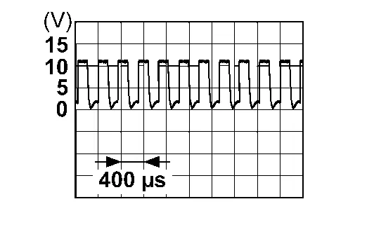 |
| Not sounding | 0 V | |||||
5 (BR) |
Ground | Back door request switch | Input | Back door request switch | ON (pressed) | 0 V |
| OFF (not pressed) | 12 V | |||||
6 (LA/L) |
Ground | CAN-H | Input/ Output | — | — | |
7 (LA/P) |
Ground | CAN-L | Input/ Output | — | — | |
8 (L) |
Ground | One touch sensor (front LH) | Input | One touch sensor (front LH) | Touched |  |
| Not touched | 12 V | |||||
9 (LA/LG) |
Ground | Power switch | Input | Power switch | Pressed | 0 V |
| Not pressed | 12 V | |||||
10 (LA/L) |
Ground | Power switch illumination power supply | Output | Power switch illumination | OFF | 0 V |
| ON | 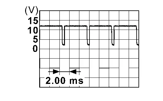 |
|||||
19 (LA/R) |
Ground | NATS antenna amp. | Input/Output |
Intelligent Key battery is removed | When a registered Intelligent Key backside is contacted to power switch | 0 V |
| Other than above |  |
|||||
| Inside key antenna (+) | Output | Power switch pressed when Intelligent Key is in the antenna detection area | 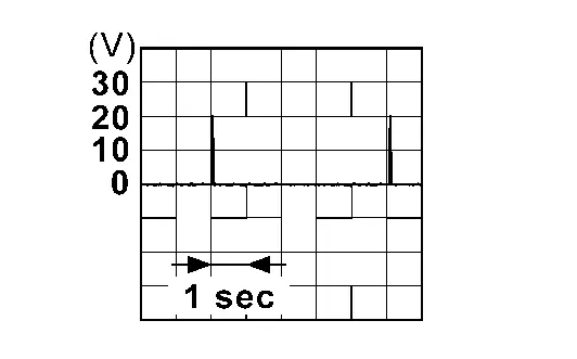 |
|||
| Power switch pressed when Intelligent Key is not in the antenna detection area | 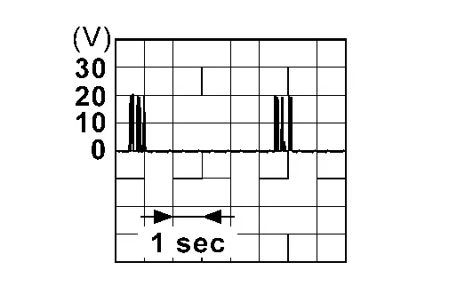 |
|||||
20 (LA/G) |
Ground | NATS antenna amp. | Input/Output | Intelligent Key battery is removed | When a registered Intelligent Key backside is contacted to power switch | 0 V |
| Other than above | 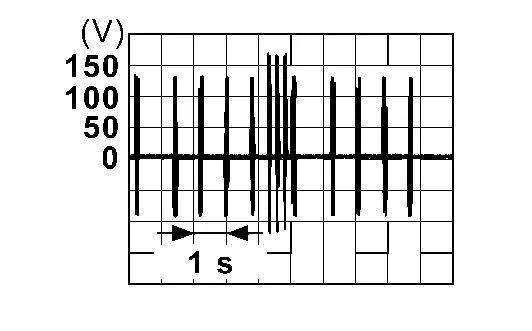 |
|||||
| Inside key antenna (-) | Output | Power switch pressed when Intelligent Key is in the antenna detection area | |
|||
| Power switch pressed when Intelligent Key is not in the antenna detection area | |
|||||
21 (W) |
Ground | One touch sensor (front RH) | Input | One touch sensor (front RH) | Touched | |
| Not touched | 12 V | |||||
22 (BR) |
Ground | One touch sensor (rear LH) | Input | One touch sensor (rear LH) | Touched | |
| Not touched | 12 V | |||||
23 (P) |
Ground | One touch sensor (rear RH) | Input | One touch sensor (rear RH) | Touched | |
| Not touched | 12 V | |||||
29 (B) |
Ground | Ground | — | — | 0 V | |
31 (SB) |
Ground | Outside key antenna (rear door RH) (-) | Output | Power switch pressed when Intelligent Key is in the antenna detection area | |
|
| Power switch pressed when Intelligent Key is not in the antenna detection area | |
|||||
32 (V) |
Ground | Outside key antenna (rear door RH) (+) | Output | Power switch pressed when Intelligent Key is in the antenna detection area | |
|
| Power switch pressed when Intelligent Key is not in the antenna detection area | |
|||||
35 (G) |
Ground | Outside key antenna (rear door LH) (-) | Output | Power switch pressed when Intelligent Key is in the antenna detection area | |
|
| Power switch pressed when Intelligent Key is not in the antenna detection area | |
|||||
36 (P) |
Ground | Outside key antenna (rear door LH) (+) | Output | Power switch pressed when Intelligent Key is in the antenna detection area | |
|
| Power switch pressed when Intelligent Key is not in the antenna detection area | |
|||||
37 (V) |
Ground | Outside key antenna (rear bumper) (-) | Output | Power switch pressed when Intelligent Key is in the antenna detection area | |
|
| Power switch pressed when Intelligent Key is not in the antenna detection area | |
|||||
38 (SB) |
Ground | Outside key antenna (rear bumper) (+) | Output | Power switch pressed when Intelligent Key is in the antenna detection area | |
|
| Power switch pressed when Intelligent Key is not in the antenna detection area | |
|||||
39 (LA/Y) |
Ground | Inside key antenna (front bumper) (-) | Output | Pressed lock button of Intelligent Key | 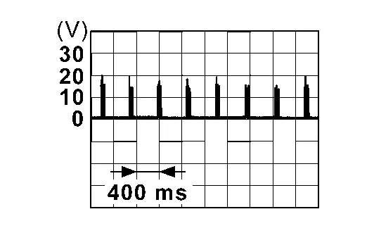 |
|
| Pressed unlock button of Intelligent Key | 0 V | |||||
40 (LA/L) |
Ground | Inside key antenna (front bumper) (+) | Output | Pressed lock button of Intelligent Key | 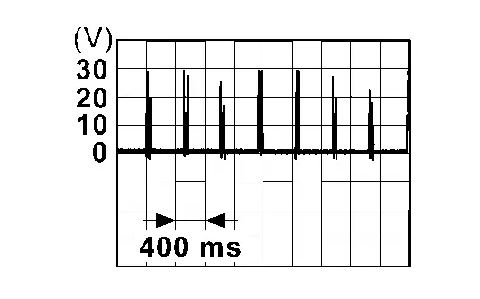 |
|
| Pressed unlock button of Intelligent Key | 0 V | |||||
Fail-safe
Refer to Fail-safe.
DTC Inspection Priority Chart
If some DTCs are displayed at the same time, perform inspections one by one based on the following priority chart.
B2001-45: Intelligent Key unit
B2002-43: Intelligent Key unit
B2010-1C: Battery voltage
B2046-42: EEPROM
B2046-46: EEPROM
B2046-55: EEPROM
U2140-87: CAN communication error (ECM)
U2141-87: CAN communication error (TCM)
U2147-87: CAN communication error (electric shift)
U2148-87: CAN communication error (brake control unit)
U214E-87: CAN communication error (combination meter)
U214F-86: CAN communication error (BCM)
U214F-87: CAN communication error (BCM)
U2150-87: CAN communication error (AIRBAG)
U2152-86: CAN communication error (ADAS control unit)
U2154-87: CAN communication error (MIU)
U215B-86: CAN communication error (IPDM E/R)
U215B-87: CAN communication error (IPDM E/R)
U216D-87: CAN communication error (TCU)
U2175-87: CAN communication error (AVM)
U218C-87: CAN communication error (gateway)
B2033-4A: Dongle not good
B2090-14: NATS antenna amplifier
B2042-4A: Electric shift authentication fail
B2043-4A: Electric shift ID discord
B2044-4A: Electric shift ID registration fail
B2045-4A: Electric shift ID discord
B2047-87: Electric shift communication fail
B2086-23: Request switch (Back door/Trunk)
B2087-08: One touch sensor (front left)
B2087-11: One touch sensor (front left)
B2087-15: One touch sensor (front left)
B2087-23: One touch sensor (front left)
B2087-24: One touch sensor (front left)
B2087-44: One touch sensor (front left)
B2088-08: One touch sensor (front right)
B2088-11: One touch sensor (front right)
B2088-15: One touch sensor (front right)
B2088-23: One touch sensor (front right)
B2088-24: One touch sensor (front right)
B2088-44: One touch sensor (front right)
B2089-08: One touch sensor (rear left)
B2089-11: One touch sensor (rear left)
B2089-15: One touch sensor (rear left)
B2089-23: One touch sensor (rear left)
B2089-24: One touch sensor (rear left)
B2089-44: One touch sensor (rear left)
B2092-08: One touch sensor (rear right)
B2092-11: One touch sensor (rear right)
B2092-15: One touch sensor (rear right)
B2092-23: One touch sensor (rear right)
B2092-24: One touch sensor (rear right)
B2092-44: One touch sensor (rear right)
B2070-68: Key registration
B203E-14: Outside antenna
B203F-14: Outside antenna
B2040-14: Outside antenna
B2041-14: Outside antenna
DTC Index
| CONSULT display | Fail-safe | Reference page |
|---|---|---|
No DTC is detected. Further testing may be required. |
— | — |
| B2001-45: Intelligent Key unit | — | DTC Description |
| B2002-43: Intelligent Key unit | — | DTC Description |
| B2010-1C: Battery voltage | — | DTC Description |
| B2033-4A: Dongle not good | — | DTC Description |
| B203E-14: Outside antenna | — | DTC Description |
| B203F-14: Outside antenna | — | DTC Description |
| B2040-14: Outside antenna | — | DTC Description |
| B2041-14: Outside antenna | — | DTC Description |
| B2042-4A: Electric shift authentication fail | × | DTC Description |
| B2043-4A: Electric shift ID discord | × | DTC Description |
| B2044-4A: Electric shift ID registration fail | × | DTC Description |
| B2045-4A: Electric shift ID discord | × | DTC Description |
| B2046-42: EEPROM | — | DTC Description |
| B2046-46: EEPROM | — | DTC Description |
| B2046-55: EEPROM | — | DTC Description |
| B2047-87: Electric shift communication fail | × | DTC Description |
| B2070-68: Key registration | — | DTC Description |
| B2086-23: Request switch (Back door/Trunk) | — | DTC Description |
| B2087-08: One touch sensor (front left) | — | DTC Description |
| B2087-11: One touch sensor (front left) | — | DTC Description |
| B2087-15: One touch sensor (front left) | — | DTC Description |
| B2087-23: One touch sensor (front left) | — | DTC Description |
| B2087-24: One touch sensor (front left) | — | DTC Description |
| B2087-44: One touch sensor (front left) | — | DTC Description |
| B2088-08: One touch sensor (front right) | — | DTC Description |
| B2088-11: One touch sensor (front right) | — | DTC Description |
| B2088-15: One touch sensor (front right) | — | DTC Description |
| B2088-23: One touch sensor (front right) | — | DTC Description |
| B2088-24: One touch sensor (front right) | — | DTC Description |
| B2088-44: One touch sensor (front right) | — | DTC Description |
| B2089-08: One touch sensor (rear left) | — | DTC Description |
| B2089-11: One touch sensor (rear left) | — | DTC Description |
| B2089-15: One touch sensor (rear left) | — | DTC Description |
| B2089-23: One touch sensor (rear left) | — | DTC Description |
| B2089-24: One touch sensor (rear left) | — | DTC Description |
| B2089-44: One touch sensor (rear left) | — | DTC Description |
| B2090-14: NATS antenna amplifier | — | DTC Description |
| B2092-08: One touch sensor (rear right) | — | DTC Description |
| B2092-11: One touch sensor (rear right) | — | DTC Description |
| B2092-15: One touch sensor (rear right) | — | DTC Description |
| B2092-23: One touch sensor (rear right) | — | DTC Description |
| B2092-24: One touch sensor (rear right) | — | DTC Description |
| B2092-44: One touch sensor (rear right) | — | DTC Description |
| U2140-87: CAN communication error (ECM) | — | DTC Description |
| U2141-87: CAN communication error (TCM) | — | DTC Description |
| U2147-87: CAN communication error (electric shift) | — | DTC Description |
| U2148-87: CAN communication error (brake control unit) | — | DTC Description |
| U214E-87: CAN communication error (combination meter) | — | DTC Description |
| U214F-86: CAN communication error (BCM) | — | DTC Description |
| U214F-87: CAN communication error (BCM) | — | DTC Description |
| U2150-87: CAN communication error (AIRBAG) | — | DTC Description |
| U2152-86: CAN communication error (ADAS control unit) | — | DTC Description |
| U2154-87: CAN communication error (MIU) | — | DTC Description |
| U215B-86: CAN communication error (IPDM E/R) | — | DTC Description |
| U215B-87: CAN communication error (IPDM E/R) | — | DTC Description |
| U216D-87: CAN communication error (TCU) | — | DTC Description |
| U2175-87: CAN communication error (AVM) | — | DTC Description |
| U218C-87: CAN communication error (gateway) | — | DTC Description |
Automatic Back Door Control Unit Nissan Ariya 2026
Reference Value
VALUES ON THE DIAGNOSIS TOOL
| Monitor Item | Condition | Value/Status | |
|---|---|---|---|
| Automatic back door status | Automatic back door system | Malfunction: All functions cannot operate | NG 1 |
| Malfunction: Only AUTO CLOSER FUNCTION can operate | NG 2 | ||
| Not used | |||
| Normal | Normal | ||
| Automatic back door position learn status | Calibration of automatic back door position information | Not complete | Yet |
| Complete | Done | ||
| Automatic back door close switch | Automatic back door close switch | Released | OFF |
| Pressed | ON | ||
| Automatic back door switch | Automatic back door switch | Released | OFF |
| Short pressed | Short | ||
| Long pressed | Long | ||
| Not used | |||
| Lock & close switch | Automatic back door lock and close switch | Released | OFF |
| Pressed | ON | ||
| Keyless signal (back door) | Intelligent Key button (back door) | Released | OFF |
| Short pressed | Short | ||
| Long pressed | Long | ||
| Not used | |||
| Automatic back door operation request (opener switch) | Back door opener switch | Not used | |
| Released | OFF | ||
| Pressed | ON | ||
| Not used | |||
| Automatic back door operation request (hands free) | Hands free sensor | Other than bellow | OFF |
| Detected | ON | ||
| Spindle sensor LH | Back door | Open | The numeral value increases |
| Close | The numeral value decreases | ||
| Spindle sensor RH | Back door | Open | The numeral value increases |
| Close | The numeral value decreases | ||
| Half latch switch | Back door | Fully closed/ half latch | OFF |
| Other than above | ON | ||
| Close switch | Back door | Other than bellow | OFF |
| Closure operation (open) | ON | ||
| Open switch | Back door | Other than bellow | OFF |
| Closure operation (close) | ON | ||
| Touch sensor LH | Touch sensor LH | Other than bellow | OFF |
| Detect obstruction | ON | ||
| Circuit open | Open | ||
| Not used | |||
| Touch sensor RH | Touch sensor RH | Other than bellow | OFF |
| Detect obstruction | ON | ||
| Circuit open | Open | ||
| Not used | |||
| Nissan Ariya Vehicle condition | Vehicle status | Sleep status | Sleep |
| Not used | |||
| AUTO ACC status (remaining time 60 seconds or less) Power switch OFF ⇒ Door open | ACC 1 | ||
AUTO ACC status (remaining time 60 seconds or more) Power switch ON ⇒ Power switch OFF |
ACC 2 | ||
| Not used | |||
| Power switch ON | IGN ON | ||
| Cranking | |||
| Nissan Ariya Vehicle set READY | Running | ||
| Restart | |||
| stop/start | |||
| Unavailable | |||
| Door lock operation | Other than bellow | OFF | |
| When door lock operation using door request switch, one touch sensor or Intelligent Key | ON | ||
| Nissan Ariya Vehicle speed | While driving | Equivalent to speedometer reading | |
| Parking brake switch | Parking brake | Off | OFF |
| On | ON | ||
| P range | Selector lever | Other than P position | OFF |
| P position | ON | ||
| Transmission type | Transmission type is displayed | AT/CVT | |
| Ignition switch | Power switch | Other than ON position | OFF |
| ON position | ON | ||
| Automatic back door control unit power supply | — | Battery voltage | |
| Sleep/wake up | Nissan Ariya Vehicle status | Sleep status | Sleep |
| Not used | |||
| Not used | |||
| Wake–up status | Wake up | ||
| Door lock interlock operate condition | Automatic back door system (automatic back door lock and close switch operation) | Other than bellow | OFF |
| Any door open | NG 1 | ||
| Intelligent Key cannot detected or Key ID unmatched | NG 2 | ||
| Normal | Normal | ||
| Diagnosis mask status | Sleep | Status 1 | |
| Auto ACC | Status 2 | ||
| Power switch ON and battery voltage 10 V or less | Status 3 | ||
| Power switch ON and battery voltage 10 V or more | Status 4 | ||
| Receives invalid CAN signal | Status 5 | ||
| Not used | |||
| Not used | |||
| Unavailable | |||
| Meter setting 1 (automatic back door) | Power back door setting | Other than bellow | Not ope |
| OFF | OFF | ||
| ON | ON | ||
| Reset | Reset | ||
| Sleep condition | Not used | ||
| Automatic back door system is operate | NG | ||
| Automatic back door system is not operate | OK | ||
| Not used | |||
| Meter setting 2(automatic back door) | Power back door setting | OFF | OFF |
| ON | ON | ||
| Automatic back door operation status | Automatic back door | Other than bellow | OFF |
| Open operation | Open | ||
| Close operation | Close | ||
| Lock and close operation | Doorlock | ||
| Automatic back door operation permission | Automatic back door system operating condition | Operation not permitted | NG |
| Activation permission | OK | ||
| When low battery voltage | Stop | ||
| Not used | |||
| Nissan Ariya Vehicle speed diagnosis 1 | When the received vehicle speed signal is normal | OK | |
| When the received Nissan Ariya vehicle speed signal is abnormal | NG | ||
| Vehicle speed diagnosis 2 | When the received Nissan Ariya vehicle speed signal is normal | OK | |
| When the received Nissan Ariya vehicle speed signal is abnormal | NG | ||
| Open switch error count | Displays the number of count up of the open switch malfunction. | 0 – 3 | |
| Close switch error count | Displays the number of count up of the close switch malfunction. | 0 – 3 | |
| Voice recognition function | ON | ||
| Automatic back door operation request (Voice recognition function) | OFF | ||
| Automatic back door operation permission (Voice recognition function) | OK | ||
| Automatic back door status (Voice recognition function) | Inactivate | ||
| Automatic back door operation status (Voice recognition function) | Inactivate | ||
TERMINAL LAYOUT
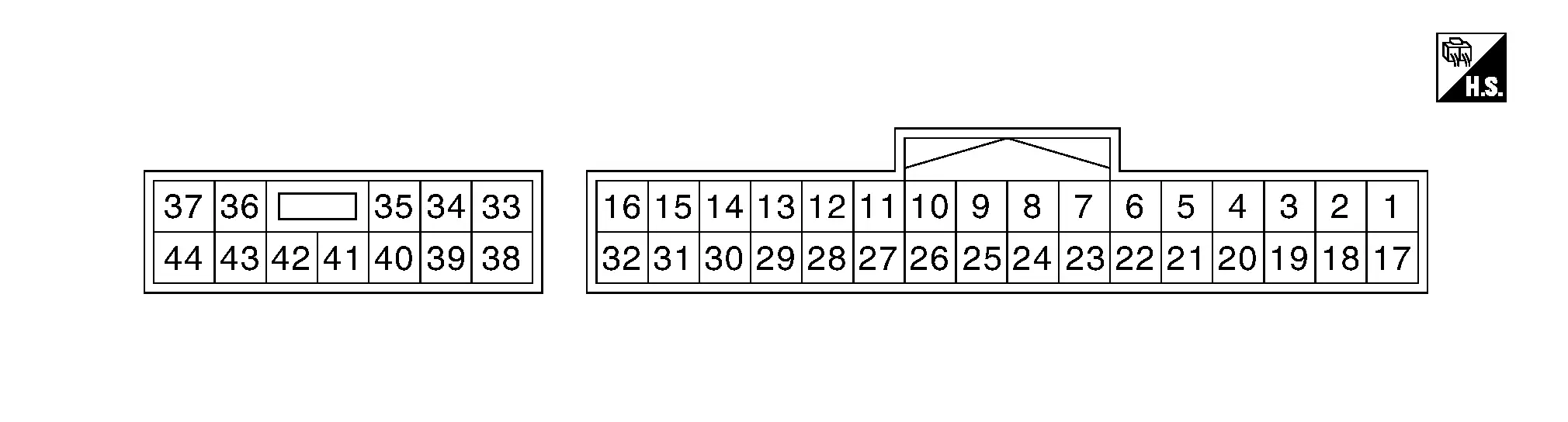
PHYSICAL VALUES
Terminal No. (Wire color) | Description | Condition | Voltage (Approx.) | |||
|---|---|---|---|---|---|---|
| (+) | (–) | Signal name | Input/Output | |||
3 (W) |
Ground | Automatic back door close switch | Input | Automatic back door close switch | Pressed | 0 - 1 V |
| Released | 9 - 16 V | |||||
4 (BG) |
Ground | Automatic back door switch | Input | Automatic back door switch | Pressed | 0 - 1 V |
| Released | 9 - 16 V | |||||
6 (GR) |
Ground | Ground | — | — | 0 - 1 V | |
9 (BR) |
Ground | Close switch signal | Input | Back door closure motor | Open operation | 0 - 1 V |
| Other than above | 9 - 16 V | |||||
10 (SB) |
Ground | Half latch switch signal | Input | Back door | Other than bellow | 0 - 1 V |
| Fully closed/half latch | 9 - 16 V | |||||
11 (V) |
Ground | Open switch signal | Input | Back door closure motor | Close operation | 0 - 1 V |
| Other than above | 9 - 16 V | |||||
12 (LG) |
Ground | Touch sensor LH signal | Input | Touch sensor LH | Detect obstruction | 0.2 - 3 V |
| Other than above | 3.4 - 6.5 V | |||||
13 (P) |
Ground | Touch sensor RH signal | Input | Touch sensor RH | Detect obstruction | 0.2 - 3 V |
| Other than above | 3.4 - 6.5 V | |||||
14 (L) |
Ground | Touch sensor ground | Input | — | 0 - 1 V | |
15 (Y) |
Ground | Automatic back door warning buzzer | Output | Automatic back door warning buzzer | Sounding (auto open/close operation) | 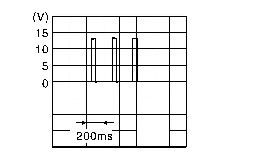 |
| Not sounding | 0 - 1 V | |||||
16 (LA/R) |
Ground | CAN - L | Input/Output | — | — | |
18 (LA/BR) |
Ground | Encoder RH B signal | Input | Back door | Moving (auto) |  |
| When stopped | 0 - 1 V or 9 - 16 V | |||||
19 (LA/Y) |
Ground | Encoder RH A signal | Input | Back door | Moving (auto) | |
| When stopped | 0 - 1 V or 9 - 16 V | |||||
20 (LA/R) |
Ground | Encoder RH power supply | Output | — | 9 - 16 V | |
21 (Y) |
Ground | Automatic back door lock and close switch | Input | Automatic back door lock and close switch | Pressed | 0 - 1 V |
| Released | 9 - 16 V | |||||
28 (LA/G) |
Ground | Encoder ground | — | — | 0 - 1 V | |
29 (LA/Y) |
Ground | Encoder LH B signal | Input | Back door | Moving (auto) | |
| When stopped | 0 - 1 V or 9 - 16 V | |||||
30 (LA/R) |
Ground | Encoder LH A signal | Input | Back door | Moving (auto) | |
| When stopped | 0 - 1 V or 9 - 16 V | |||||
31 (LA/B) |
Ground | Encoder LH power supply | Output | — | 9 - 16 V | |
32 (LA/L) |
Ground | CAN - H | Input/Output | — | — | |
33 (LA/L) |
Ground | Back door closure motor (open) | Output | Back door | Open operation | 9 - 16 V |
| Other than above | 0 - 1 V | |||||
34 (LA/W) |
Ground | Back door closure motor (close) | Output | Back door | Close operation | 9 - 16 V |
| Other than above | 0 - 1 V | |||||
35 (BR) |
Ground | Spindle motor RH (open) | Output | Back door | Auto open operation | 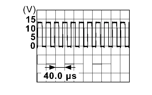 |
| Auto close operation | 0 - 1 V | |||||
37 (BR) |
Ground | Power supply (BAT) | Input | — | Battery voltage | |
38 (BR) |
Ground | Spindle motor LH (open) | Output | Back door | Auto open operation | |
| Auto close operation | 0 - 1 V | |||||
39 (G) |
Ground | Spindle motor LH (close) | Output | Back door | Auto close operation | |
| Auto open operation | 0 - 1 V | |||||
40 (G) |
Ground | Spindle motor RH (close) | Output | Back door | Auto close operation | |
| Auto open operation | 0 - 1 V | |||||
42 (B) |
Ground | Ground | — | — | 0 - 1 V | |
44 (B) |
Ground | Ground (noise shield) | — | — | 0 - 1 V | |
Fail-safe
Refer to Fail-safe.
DTC Inspection Priority Chart
If some DTCs are displayed at the same time, perform inspections one by one based on the following priority chart.
B2428–44: Automatic back door control unit
B2428–45: Automatic back door control unit
B2428–46: Automatic back door control unit
B2428–49: Automatic back door control unit
B2428–52: Automatic back door control unit
B2428–54: Automatic back door control unit
U0075–00: Control module communication Bus C Off
U2141–87: CAN communication error (TCM)
U2148–87: CAN communication error (brake control unit)
U214E–87: CAN communication error (combination meter)
U214F–87: CAN communication error (BCM)
U215B–87: CAN communication error (IPDM E/R)
B2409–12: Half latch switch
B2409–14: Half latch switch
B2416–15: Touch sensor circuit RH open
B2417–15: Touch sensor circuit LH open
B2419–12: Open switch
B2419–14: Open switch
B2420–12: Close switch
B2420–14: Close switch
B2422–78: Back door position abnormal
B2422–79: Back door position abnormal
B2426–11: Spindle sensor LH
B2426–12: Spindle sensor LH
B2426–13: Spindle sensor LH
B2426–25: Spindle sensor LH
B2427–11: Spindle sensor RH
B2427–12: Spindle sensor RH
B2427–13: Spindle sensor RH
B2427–25: Spindle sensor RH
B242A–11: Closure motor
B242A–12: Closure motor
B242A–13: Closure motor
B242A–19: Closure motor
B242A–98: Closure motor
B242F–11: Automatic back door warning buzzer
B242F–12: Automatic back door warning buzzer
B242F–13: Automatic back door warning buzzer
B242F–19: Automatic back door warning buzzer
B2436–11: Spindle motor LH
B2436–12: Spindle motor LH
B2436–13: Spindle motor LH
B2436–19: Spindle motor LH
B2436–98: Spindle motor LH
B2437–11: Spindle motor RH
B2437–12: Spindle motor RH
B2437–13: Spindle motor RH
B2437–19: Spindle motor RH
B2437–98: Spindle motor RH
DTC Index
| CONSULT display | Fail-safe | Reference page |
|---|---|---|
| B2409-12: Half latch switch | × | DTC Description |
| B2409-14: Half latch switch | × | DTC Description |
| B2416-15: Touch sensor circuit RH open | × | DTC Description |
| B2417-15: Touch sensor circuit LH open | × | DTC Description |
| B2419-12: Open switch | × | DTC Description |
| B2419-14: Open switch | × | DTC Description |
| B2420-12: Close switch | × | DTC Description |
| B2420-14: Close switch | × | DTC Description |
| B2422-78: Back door position abnormal | × | DTC Description |
| B2422-79: Back door position abnormal | × | DTC Description |
| B2426-11: Spindle sensor LH | × | DTC Description |
| B2426-12: Spindle sensor LH | × | DTC Description |
| B2426-13: Spindle sensor LH | × | DTC Description |
| B2426-25: Spindle sensor LH | × | DTC Description |
| B2427-11: Spindle sensor RH | × | DTC Description |
| B2427-12: Spindle sensor RH | × | DTC Description |
| B2427-13: Spindle sensor RH | × | DTC Description |
| B2427-25: Spindle sensor RH | × | DTC Description |
| B2428-44: Automatic back door control unit | × | DTC Description |
| B2428-45: Automatic back door control unit | × | DTC Description |
| B2428-46: Automatic back door control unit | × | DTC Description |
| B2428-49: Automatic back door control unit | × | DTC Description |
| B2428-52: Automatic back door control unit | × | DTC Description |
| B2428-54: Automatic back door control unit | × | DTC Description |
| B242A-11: Closure motor | × | DTC Description |
| B242A-12: Closure motor | × | DTC Description |
| B242A-13: Closure motor | × | DTC Description |
| B242A-19: Closure motor | × | DTC Description |
| B242A-98: Closure motor | × | DTC Description |
| B242F-11: Automatic back door warning buzzer | — | DTC Description |
| B242F-12: Automatic back door warning buzzer | — | DTC Description |
| B242F-13: Automatic back door warning buzzer | — | DTC Description |
| B242F-19: Automatic back door warning buzzer | — | DTC Description |
| B2436-11: Spindle motor LH | × | DTC Description |
| B2436-12: Spindle motor LH | × | DTC Description |
| B2436-13: Spindle motor LH | × | DTC Description |
| B2436-19: Spindle motor LH | × | DTC Description |
| B2436-98: Spindle motor LH | × | DTC Description |
| B2437-11: Spindle motor RH | × | DTC Description |
| B2437-12: Spindle motor RH | × | DTC Description |
| B2437-13: Spindle motor RH | × | DTC Description |
| B2437-19: Spindle motor RH | × | DTC Description |
| B2437-98: Spindle motor RH | × | DTC Description |
| U0075–00: Control module communication Bus C Off | × | DTC Description |
| U2118–87: CAN communication error (Intelligent Key) | × | DTC Description |
| U2141–87: CAN communication error (TCM) | × | DTC Description |
| U2148–87: CAN communication error (brake control unit) | × | DTC Description |
| U214E–87: CAN communication error (combination meter) | × | DTC Description |
| U214F–87: CAN communication error (BCM) | × | DTC Description |
| U215B–87: CAN communication error (IPDM E/R) | × | DTC Description |
Hands Free Sensor Control Unit Nissan Ariya 2023
Reference Value
TERMINAL LAYOUT

PHYSICAL VALUES
Terminal No. (Wire color) | Description | Condition | Voltage (Approx.) | |||
|---|---|---|---|---|---|---|
| (+) | (–) | Signal name | Input/Output | |||
1 (L) |
Ground | Serial communication | Input/Output | Power switch ON | 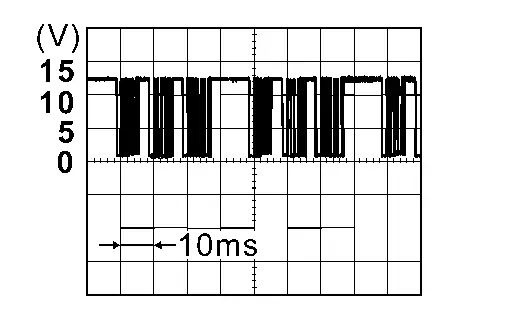 |
|
2 (Y) |
Ground | Power supply (BAT) | Input | — | 8 – 16 V | |
3 (B) |
Ground | Ground | — | — | 0 V | |
5 (-) |
Ground | Hands free sensor (upper side) output signal | Output | — | — | |
6 (-) |
Ground | Hands free sensor (upper side) input signal | Input | — | — | |
7 (-) |
Ground | Hands free sensor (lower side) output signal | Output | — | — | |
8 (-) |
Ground | Hands free sensor (lower side) input signal | Input | — | — | |