Removal and Installation
- Inverter (rear)
- Rear Traction Motor
Inverter (rear) Nissan Ariya 2023
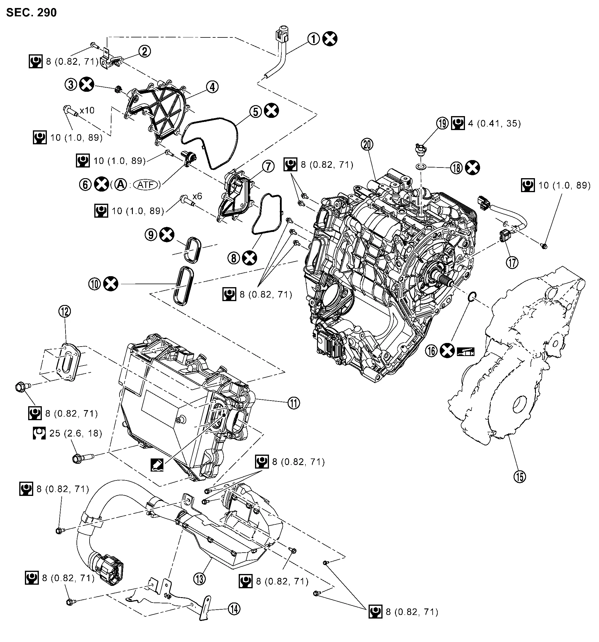
Exploded View
 |
Air breather hose |  |
Bracket |  |
Breather |
 |
Excitation cover |  |
Gasket |  |
Rear traction motor stator temperature sensor joint connector |
 |
3-phase bus bar cover |  |
Gasket |  |
Seal |
 |
Seal |  |
Inverter (rear) |  |
High voltage harness cover |
 |
High voltage harness |  |
Bracket |  |
Rear final drive assembly |
 |
O-ring |  |
Resolver harness |  |
Gasket |
 |
Plug |  |
Rear traction motor assembly | ||
 |
O-ring | ||||
 : N·m (kg-m, in-lb) |
|||||
 : N·m (kg-m, ft-lb) |
|||||
 : Always replace after every disassembly. |
|||||
 : Apply ATF (Genuine NISSAN Matic S). |
|||||
 : Apply lithium-based grease including molybdenum disulphide. |
|||||
 : Apply Genuine Silicone RTV or equivalent. Refer to HOW TO USE THIS MANUAL : Recommended Chemical Products and Sealants. |
|||||
Removal and Installation
DANGER: Since hybrid vehicles and electric vehicles contain a high voltage battery, there is the risk of electric shock, electric leakage, or similar accidents if the high voltage component and Nissan Ariya vehicle are handled incorrectly. Be sure to follow the correct work procedures when performing inspection and maintenance.
REMOVAL
Disconnect high voltage circuit. Refer to HOW TO DISCONNECT HIGH VOLTAGE : Precautions.
Check voltage in high voltage circuit. Refer to CHECK VOLTAGE IN HIGH VOLTAGE CIRCUIT : Precautions.
Remove rear suspension member assembly together with rear final drive assembly and rear traction motor with inverter (rear) from Nissan Ariya vehicle. Refer to REAR SUSPENSION MEMBER : Removal & Installation.
Remove rear final drive assembly, rear traction motor and inverter (rear) as a set from rear suspension member assembly, after removing high voltage harness and water hoses. Refer to Removal and Installation.
Remove air breather hose .
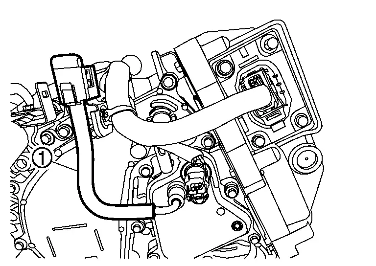
Disconnect harness connector from rear traction motor stator temperature sensor joint connector .
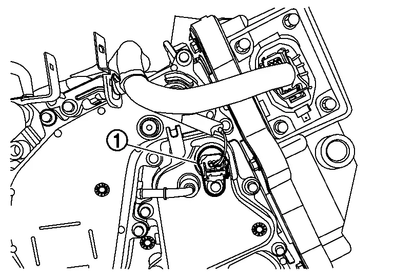
Disconnect harness connector (low voltage connector) for inverter (rear).
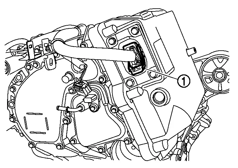
Remove each harness and each bracket.
Remove excitation cover .


Remove gasket from excitation cover.

Remove excitation bus bar terminal fixing bolts.
Remove 3-phase bus bar cover .

Disconnect harness connector from rear traction motor stator temperature sensor joint connector.

Remove gasket from 3-phase bus bar cover.
Remove 3-phase bus bar terminal fixing bolts.

Remove rear motor mounting insulator assembly (front side) . Refer to Removal and Installation.
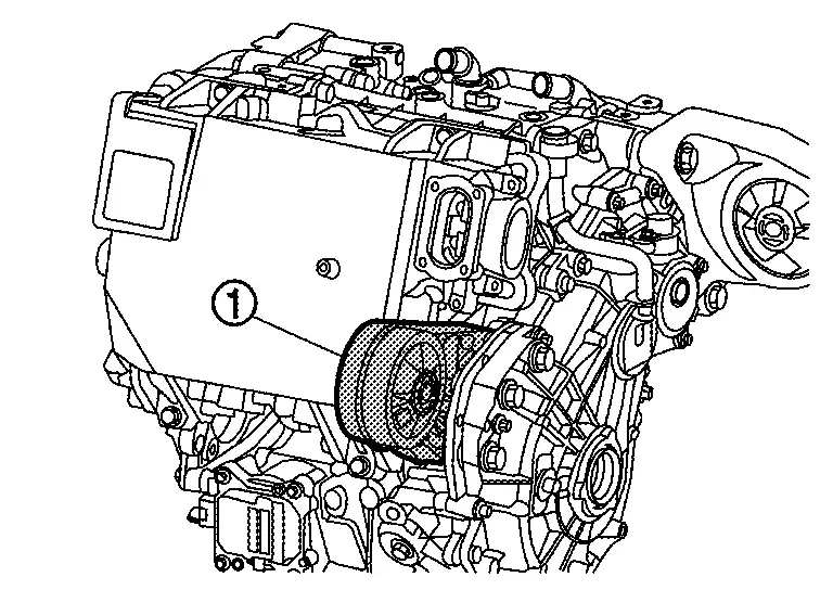
Remove inverter (rear) after removing mounting bolts.

Remove the seal on the excitation bus bar opening and the seal on the 3-phase bus bar opening.
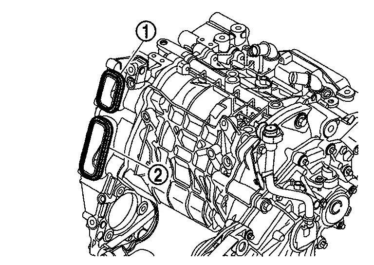
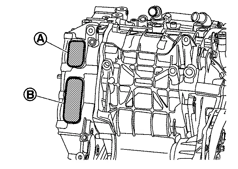
INSTALLATION
Note the following, and install in the reverse order of removal.
For each tightening torque, refer to Exploded View.
When the inverter (rear) is installed, never bend the 3-phase bus bar and the excitation bus bar or give impact.
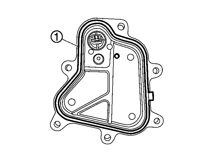
When installing gasket
to 3-phase bus bar cover, set the tab in the position as shown in the figure.
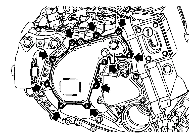
When installing 3-phase bus bar cover
, tighten the mounting bolts to the specified torque in the order shown in the figure after temporarily tightening each bolt.
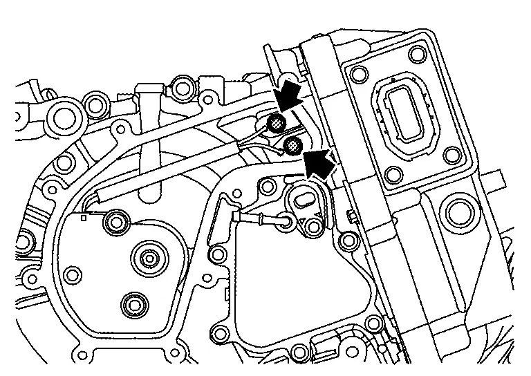
When installing the excitation wiring harness terminals onto the excitation bus bar, install the red harness terminal (Ex +)
onto the lower excitation bus bar, and the blue harness terminal (Ex –)  onto the upper excitation bus bar.
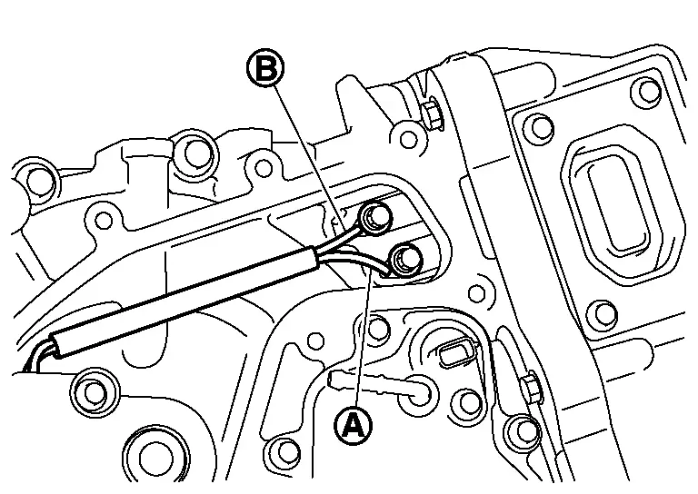
When installing gasket
to excitation cover, set the tab in the position as shown in the figure.
When installing excitation cover
, tighten the mounting bolts to the specified torque in the order shown in the figure after temporarily tightening each bolt.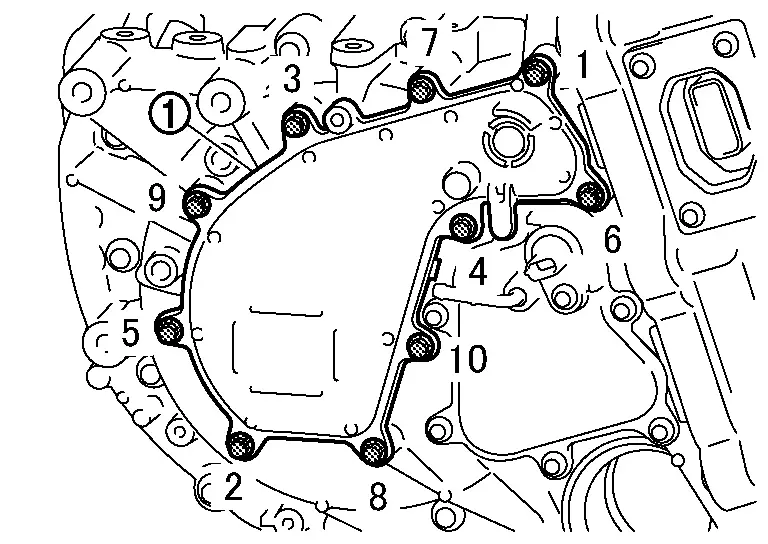
Replace rear traction motor stator temperature sensor joint connector, if rear traction motor stator temperature sensor joint connector is removed from 3-phase bus bar cover.
Replace air breather hose, if air breather hose is removed from 3-phase bus bar cover.
Replace breather, if breather is removed from excitation cover.
After all the installation is completed, perform inspection after installation. Refer to Inspection.
When the inverter (rear) is replaced, perform adjustment after installation. Refer to Adjustment.
Inspection
INSPECTION AFTER INSTALLATION
After installing the inverter (rear) to the vehicle, perform the following equipotential inspection and confirm that it is less than the standard value.
Between inverter (rear) and other high voltage system
Between inverter (rear) and Nissan Ariya vehicle body (bolt of body ground)
Standard : Less than 0.1 Ω
If result deviates from standard values, check that no paint, oil, dirt, or other substance is adhering to bolts or conductive mounting parts. If any such substance is adhering, clean the surrounding area and remove the substance.
Adjustment
ADJUSTMENT AFTER INSTALLATION
When the inverter (rear) is replaced, perform required procedure. Refer to Work Procedure.
Rear Traction Motor Nissan Ariya
Exploded View
INVERTER (REAR) AND REAR TRACTION MOTOR
|
Air breather hose | |
Bracket | |
Breather |
|
Excitation cover | |
Gasket | |
Rear traction motor stator temperature sensor joint connector |
|
3-phase bus bar cover | |
Gasket | |
Seal |
|
Seal | |
Inverter (rear) | |
High voltage harness cover |
|
High voltage harness | |
Bracket | |
Rear final drive assembly |
|
O-ring | |
Resolver harness | |
Gasket |
|
Plug | |
Rear traction motor assembly | ||
|
O-ring | ||||
| : N·m (kg-m, in-lb) |
|||||
| : N·m (kg-m, ft-lb) |
|||||
| : Always replace after every disassembly. |
|||||
| : Apply ATF (Genuine NISSAN Matic S). |
|||||
| : Apply lithium-based grease including molybdenum disulphide. |
|||||
| : Apply Genuine Silicone RTV or equivalent. Refer to HOW TO USE THIS MANUAL : Recommended Chemical Products and Sealants. |
|||||
REAR TRACTION MOTOR MOUNTING
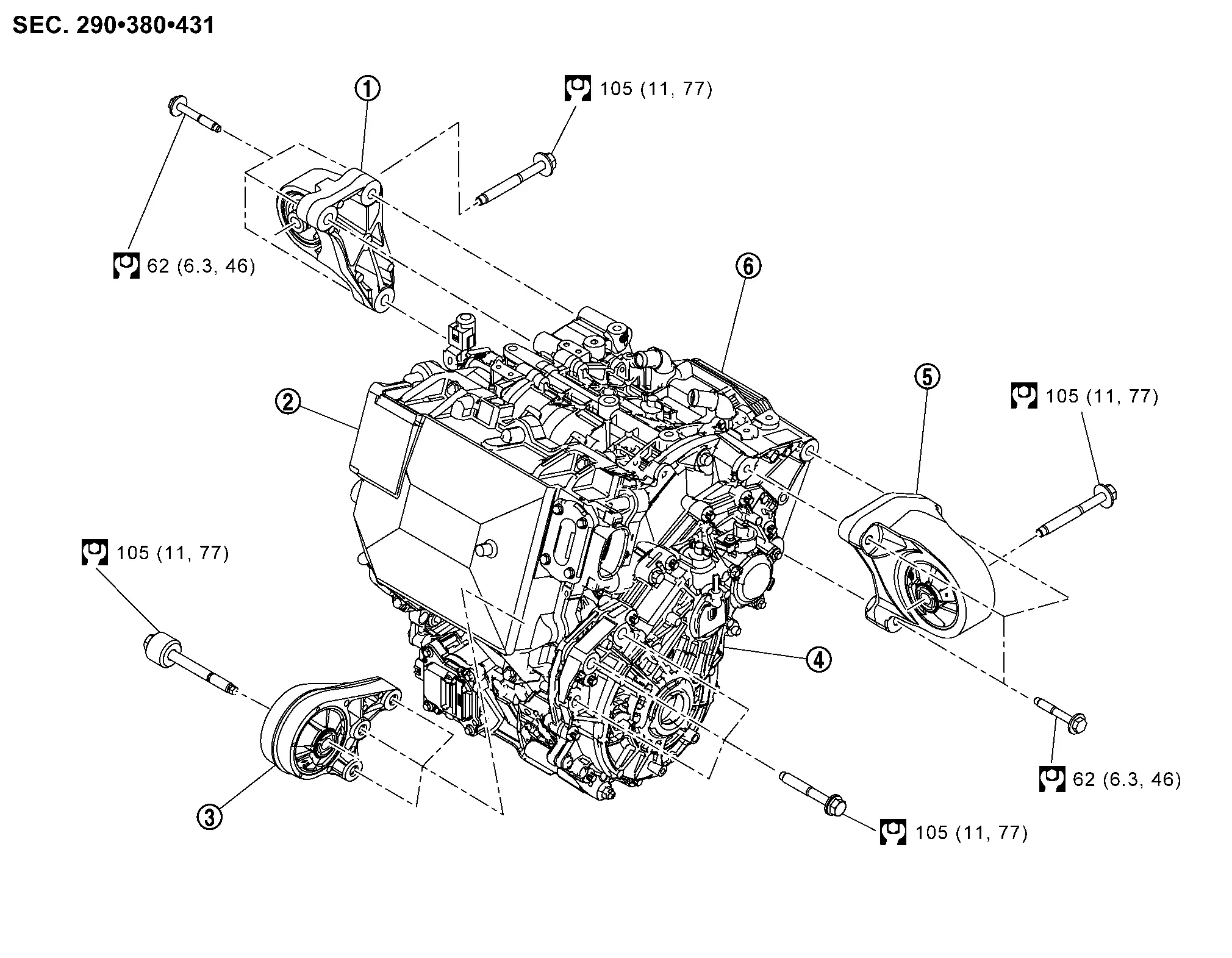
|
Rear motor mounting insulator assembly (right side) | |
Inverter (rear) | |
Rear motor mounting insulator assembly (front side) |
|
Rear final drive assembly | |
Rear motor mounting insulator assembly (left side) | |
Rear traction motor assembly |
| : N·m (kg-m, ft-lb) |
|||||
Removal and Installation
DANGER:Since hybrid vehicles and electric vehicles contain a high voltage battery, there is the risk of electric shock, electric leakage, or similar accidents if the high voltage component and Nissan Ariya vehicle are handled incorrectly. Be sure to follow the correct work procedures when performing inspection and maintenance.
REMOVAL
Disconnect high voltage circuit. Refer to HOW TO DISCONNECT HIGH VOLTAGE : Precautions.
Check voltage in high voltage circuit. Refer to CHECK VOLTAGE IN HIGH VOLTAGE CIRCUIT : Precautions.
Remove rear suspension member assembly together with rear final drive assembly and rear traction motor with inverter (rear) from Nissan Ariya vehicle. Refer to REAR SUSPENSION MEMBER : Removal & Installation.
Remove high voltage harness cover after removing mounting bolts.
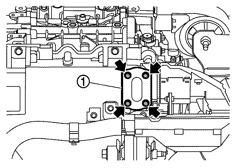
Remove high voltage harness terminal fixing bolts.
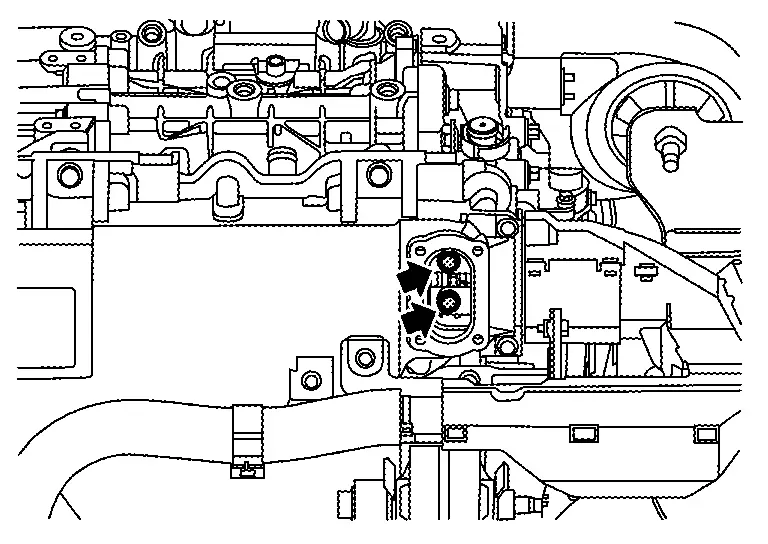
Remove high voltage harness and bracket from inverter (rear) after removing mounting bolts.
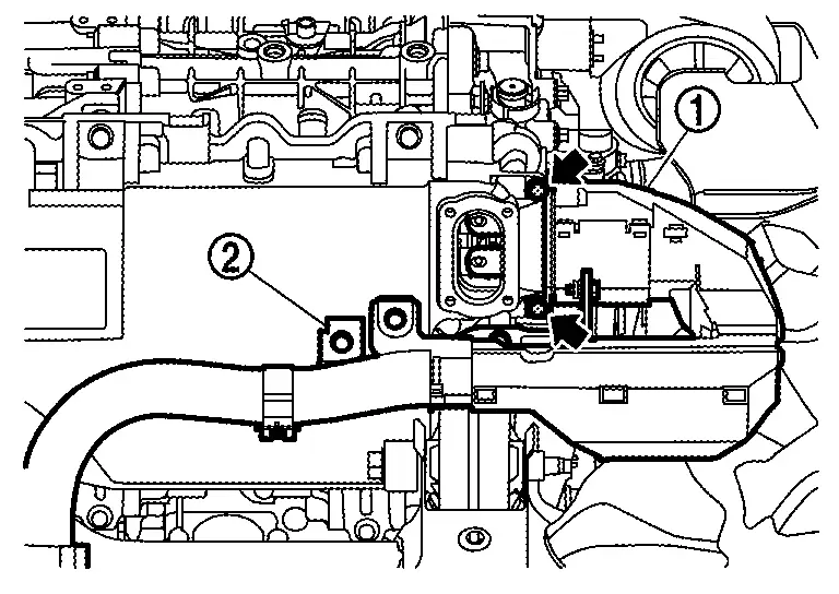
Remove water hoses .
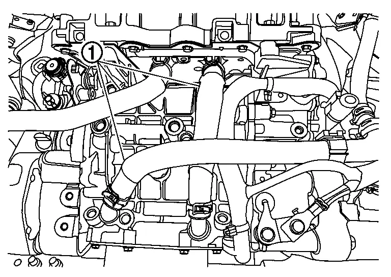
Remove harness and/or cable to ground (earth).
Attach sling belts to inverter (rear), rear traction motor and rear final drive assembly, and prepare to separate them from the rear suspension member assembly.
Remove the fixing bolts between rear suspension member and rear motor mounting insulator assembly (left side, right side, and front side).

Use a hoist to lift up the inverter (rear), the rear traction motor, and the rear final drive assembly as a set, and remove them from the rear suspension member assembly.

Slowly lower the inverter (rear), the rear traction motor, and the rear final drive assembly together, then remove the sling belts.
Remove inverter (rear) and rear final drive assembly from rear traction motor.
Rear final drive assembly: Refer to REAR FINAL DRIVE ASSEMBLY : Unit Removal & Installation.
Inverter (rear): Refer to Removal and Installation.
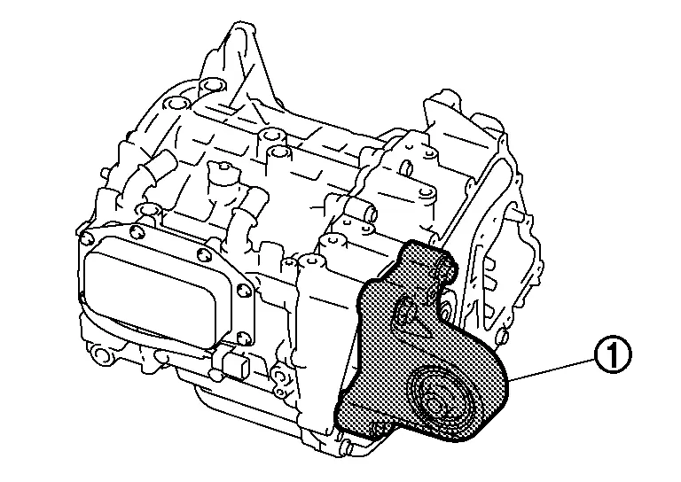
Remove rear motor mounting insulator assembly (right side) .
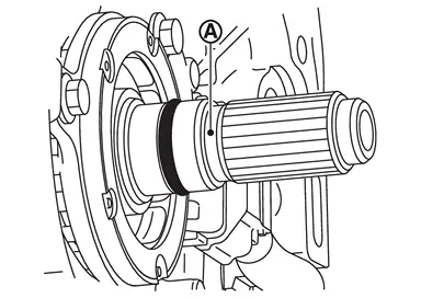
Remove O-ring from rear traction motor shaft.

INSTALLATION
Note the following, and install in the reverse order of removal.
For each tightening torque, refer to Exploded View.
When removing rear final drive assembly from rear traction motor, replace O-ring of rear traction motor shaft. Also when installing, apply lithium-based grease including molybdenum disulphide to the O-ring.
When installing rear final drive assembly
to rear traction motor , align markings on rear final drive input shaft and rear traction motor shaft.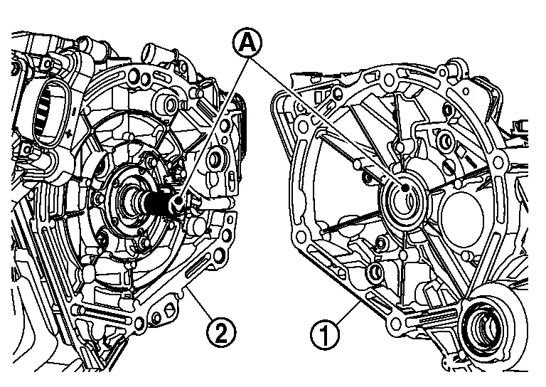
When installing rear motor mounting insulator assembly (right side)
to rear traction motor assembly, tighten the mounting bolts to the specified torque in the order shown in the figure after temporarily tightening mounting bolt .
When installing rear motor mounting insulator assembly (left side)
to rear final drive assembly, tighten the mounting bolts to the specified torque in the order shown in the figure after temporarily tightening mounting bolt .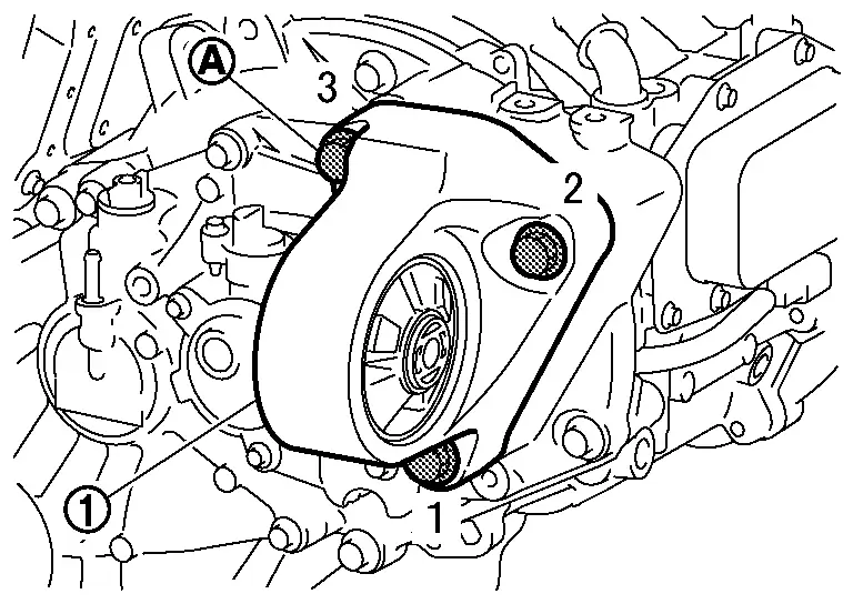
When installing rear motor mounting insulator assembly (front side)
to rear final drive assembly, tighten the mounting bolts to the specified torque in the order shown in the figure after temporarily tightening mounting bolt .
When installing rear motor mounting insulator assembly (left side, right side, and front side) to rear suspension member, according to the following procedure.
Temporarily tighten the fixing bolt between rear suspension member and rear motor mounting insulator assembly (front side).
Temporarily tighten the fixing bolts with rear suspension member in the order from rear motor mounting insulator assembly (right side) to rear motor mounting insulator assembly (left side).
Tighten the fixing bolt between rear suspension member and rear motor mounting insulator assembly (front side) to the specified torque.
Tighten the fixing bolts with rear suspension member in the order from rear motor mounting insulator assembly (right side) to rear motor mounting insulator assembly (left side) to the specified torque.
When no external force is applied, check that there is no abnormal sagging or twisting of the mounts.
After installing rear motor mounting insulator assembly (left side, right side, and front side) to rear suspension member, check that each clearance (A, B, and C) is the following dimension.
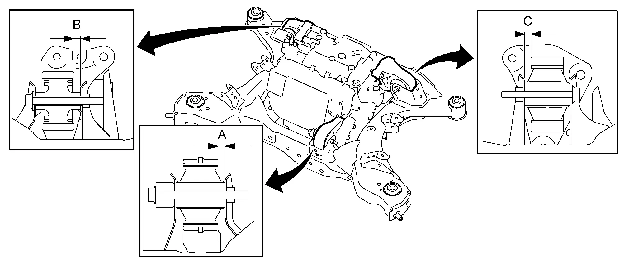
Reference value A : 10.2±1.5 mm (0.402±0.059 in) B : 11.2±1.5 mm (0.441±0.059 in) C : 10.2±1.5 mm (0.402±0.059 in)
When installing high voltage harness cover, apply liquid gasket to mating surface on inverter (rear).
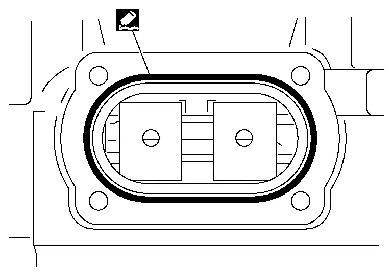
For applying liquid gasket, refer to Exploded View.
After all the installation is completed, perform inspection after installation. Refer to Inspection.
When the rear traction motor is replaced, perform adjustment after installation. Refer to Adjustment.
Inspection
INSPECTION AFTER INSTALLATION
After installing the rear traction motor to the vehicle, perform the following equipotential inspection and confirm that it is less than the standard value.
Between rear traction motor and other high voltage system
Between rear traction motor (aluminum area) and Nissan Ariya vehicle body (bolt of body ground)
Standard : Less than 0.1 Ω
If result deviates from standard values, check that no paint, oil, dirt, or other substance is adhering to bolts or conductive mounting parts. If any such substance is adhering, clean the surrounding area and remove the substance.
Adjustment
ADJUSTMENT AFTER INSTALLATION
When the rear traction motor is replaced, it is necessary to write the resolver offset value and rotor resistance value into the inverter (rear). Refer to Work Procedure.