Ev Battery System
- Diagnosis and Repair Work Flow
- Service When Replacing Li-Ion Battery Parts
- Additional Service When Replacing Li-Ion Battery Controller
- Additional Service When Replacing Module
- Module Charge Balance
Diagnosis and Repair Work Flow Nissan Ariya
Work Flow
DETAILED FLOW
GET INFORMATION FOR SYMPTOM
Get detailed information from the customer about the symptom (the condition and the environment when the incident/malfunction occurred) using the “Diagnostic Work Sheet”. Refer to Diagnostic Work Sheet.)
>>GO TO 2.
CHECK DTC AND FREEZE FRAME DATA
Perform self-diagnosis for "HIGH VOLTAGE BATTERY" and "HIGH VOLTAGE BATTERY 2" by connecting CONCULT.
If DTC is displayed, perform the following work.
Store DTC and freeze frame data.
Investigate the relationship between the cause specified by DTC and the malfunction information from customer.
Are any DTCs detected?
YES>>GO TO 4.
NO>>GO TO 3.
CONFIRM THE SYMPTOM
Try to confirm the symptom described by the customer on the car. Also study if it is fail-safe related symptoms. Refer to Fail-safe. "Diagnosis Work Sheet" is useful to verify the incident. Verify relation between the symptom and the condition when the symptom is detected.
Are any described symptoms occurred?
>>GO TO 5.
NO>>Perform DTC diagnosis simulation test. Refer to Intermittent Incident.
PERFORM DTC CONFIRMATION PROCEDURE
Perform DTC CONFIRMATION PROCEDURE for the displayed DTC, and then check that DTC is detected again.
When multi DTCs are detected, determine diagnosis order by referring to "DTC Inspection Priority Chart".
Is DTC detected?
>>GO TO 5.
NO>>Perform DTC diagnosis simulation test. Refer to Intermittent Incident.
DETECT MALFUNCTIONING PART BY DIAGNOSIS PROCEDURE
Inspect according to Diagnosis Procedure of the system.
>>GO TO 6.
REPAIR OR REPLACE THE MALFUNCTIONING PART
Repair or replace the malfunctioning part.
Reconnect parts or connectors disconnected during Diagnosis Procedure again after repair and replacement.
Check DTC. If DTC is displayed, erase it?
>>GO TO 7.
FINAL CHECK
Check result of repair and replacement work, and perform DTC CONFIRMATION PROCEDURE or Component.
Function Check again, and check that the symptom is not detected the other malfunction is not occurred.
>>Before delivery of the Nissan Ariya vehicle to the customer, always erase DTC
Diagnostic Work Sheet
DESCRIPTION
There are many operating conditions that lead to the malfunction of EV battery system. A good grasp of such conditions can make troubleshooting faster and more accurate.
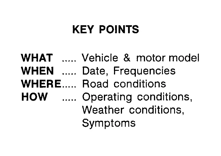
In general, each customer feels differently about symptoms. It is important to fully understand the symptoms or conditions of customer complaint.
Utilize the diagnostic worksheet in order to organize all the information for troubleshooting.
WORKSHEET SAMPLE
| Question Sheet | |||||||
|---|---|---|---|---|---|---|---|
Customer name MR/MS |
Incident Date | VIN | |||||
| Model & Year | In Service Date | ||||||
| Trans. | Mileage | km/mile | |||||
| Symptoms | □ Does not switch to READY | □ EV system warning lamp is on | □ Power limitation indicator lamp is on | ||||
| □ Water leak* | □ Noise* | □ Vibration* | □ Shock* | □ Gear noise* | |||
| □ Unable to drive* | □ Poor acceleration* | □ Poor torque* | □ Radio noise* | ||||
| □ Does not charge | □ Other* | *: If applied, enter in detail | |||||
| Detailed symptom | |||||||
| Onomatopoeia | |||||||
| Frequency | □ All the time | □ Once | □ Sometimes ( times a day) | □ Others | |||
| Charging condition | □ Full | □ Medium | □ Low | ||||
| Weather conditions | □ Not affected | ||||||
| Weather | □ Fine | □ Cloudy | □ Raining | □ Snowing | □ Others ( ) | ||
| Temp. | □ Hot | □ Warm | □ Cool | □ Cold | □ Temp. [Approx. °C ( °F)] | ||
| Humidity | □ High | □ Middle | □ Low | □ Humidity (Approx. %) | |||
| Road conditions | □ Not affected | □ In town | □ Freeway | □ Off road (Up / Down) | □ Rough road | ||
| □ Flat road | □ While turning (Right / Left) | □ Bump | |||||
| □ Others | |||||||
| Shift position | □ Not affected | ||||||
| □ P position | □ R position | □ N position | □ D position | □ ECO mode | |||
| Driving conditions | □ Not affected | ||||||
| □ Power switch ON → OFF | □ Power switch OFF → ON | □ READY (stopping Nissan Ariya vehicle) | |||||
| □ While cruising | □ While decelerating | □ Just before stopping | □ Just after stopping | □ D position (stopping Nissan Ariya vehicle) | |||
| □ While recharging | □ Other | ||||||
| □ Nissan Ariya Vehicle speed [ km/h ( MPH)] | □ Accelerator pedal ( / 8) | ||||||
| □ Battery level (Low / Middle / High) | |||||||
| Moments when symptom disappears | □ Disappears while driving | □ Disappears when stopped | □ Disappears with shift operation | ||||
| □ Disappears when power switch is pushed OFF | □ Disappears when battery charge is stopped | □ Does not disappear | |||||
| □ Others | |||||||
| Others | |||||||
Service When Replacing Li-Ion Battery Parts Nissan Ariya 2026
Work Item List
When replacing Li-ion battery assembly or parts in Li-ion battery, refer to the following table. The numbers included in the table represent the work sequence.
| Supplementary work | Replacing parts | Reference | |||||
|---|---|---|---|---|---|---|---|
| Li-ion battery assembly (With LBC) | LBC | Some of modules | Battery junction box | ||||
| LBC | Before replacing parts | Save battery information | 1 | Refer to Work Procedure. | |||
| After replacing parts | LBC programming | 1 | Refer to Work Procedure. | ||||
| Write battery information | 2 | Refer to Work Procedure. | |||||
| Module | Before replacing parts | Adjust module voltage | 1 | Refer to Work Procedure. | |||
Additional Service When Replacing Li-Ion Battery Controller Nissan Ariya SUV
Description
When replacing Li-ion battery controller (LBC), the following procedures must be performed.
Work Procedure
Work before replacement
The following procedure is performed before removing battery pack from vehicle.
SAVE THE LBC INTERNAL INFORMATION
 With CONSULT
Perform saving Nissan Ariya vehicle internal information according to "Replace ECU" in CONSULT Operation Manual.
>>Replace Li-ion battery controller. Refer to Removal & Installation.
Work after replacement
Vehicle specification needs to be written with CONSULT because it is not written after replacing the Li-ion battery controller (LBC).
CONSULT connects to network and then it downloads the configuration data from the server. Then CONSULT writes the Nissan Ariya vehicle specification to the Li-ion battery controller (LBC).
WRITING VEHICLE SPECIFICATION
With CONSULT
Perform writing Nissan Ariya vehicle specification to Li-ion battery controller (LBC) according to "Replace ECU" in CONSULT Operation Manual.
>>GO TO 2.
CHECK DTC
Press and hold the power switch for at least 2 seconds to turn OFF high voltage system and check that charge indicator is OFF.
After turning OFF high voltage system, open driver's door, get out the car, close driver's door, and wait at least 5 minutes.
Power switch ON.
Check DTC. If DTC is detected, erase DTC.
WORK END
Additional Service When Replacing Module Nissan Ariya first Gen
Description
When replacing some of modules, the following procedure must be performed. For replacing all of modules, this procedure is not required. (For details, refer to Work Procedure.)
Work Procedure
CHECK MAXIMUM CELL VOLTAGE
With CONSULT
Power switch ON.
Select “Data Monitor” of “HIGH VOLTAGE BATTERY”.
Record “Maximum cell voltage”.
GO TO 2.
REMOVAL OF MODULE
Remove module.
Refer to Disassembly & Assembly.
Refer to Disassembly & Assembly.
GO TO 3.
ADJUSTMENT OF MODULE VOLTAGE
Adjust the voltage of module requiring replacement. Refer to Work Procedure.
>>GO TO 4.
INSTALLATION OF MODULE
Install new module.
Refer to Disassembly & Assembly.
Refer to Disassembly & Assembly.
WORK END
Module Charge Balance Nissan Ariya
Description
If a malfunction (e.g. abnormal voltage) occurs in a Li-ion battery cell, the module which includes the malfunctioning cell must be replaced. When replacing a module with a new one, its voltage is required to be adjusted to the adjusting voltage calculated from the Maximum cell voltage of normal cells.
To prevent the damage to the module balancer, follow the instructions.
Be sure to choose the monitoring cable which adapted to a module type.
Because the shape of the module connector is same, the monitoring cable can be connected to all module type.
If an incompatible monitoring cable is connected, the module balancer may be damaged.
Do not remove the module gauge from a monitoring cable. The module gauge (colored acrylic board) is distinguished from a monitoring cable with the same color by each module type.
For details, refer to Work Procedure.
Work Procedure
CHECK ADJUSTMENT VOLTAGE VALUE
Check the recorded “Maximum cell voltage”.
Calculate the adjustment value as follows from "Maximum cell voltage".
ModuleType Adjustment voltage value 2P9S (2 Parallel 9 Series) : Maximum cell voltage× 9 2P6S (2 Parallel 6 Series) : Maximum cell voltage× 6 Example: 3.925 V (Maximum cell voltage) × 9= 35.325 V (Adjustment voltage value)
GO TO 2
VOLTAGE ADJUSTMENT WITH MODULE CHARGE BALANCER
Set the new module
 to the module balancer [KV9911-8000 (J-52665)]
 and fix with the module fixation band
 .
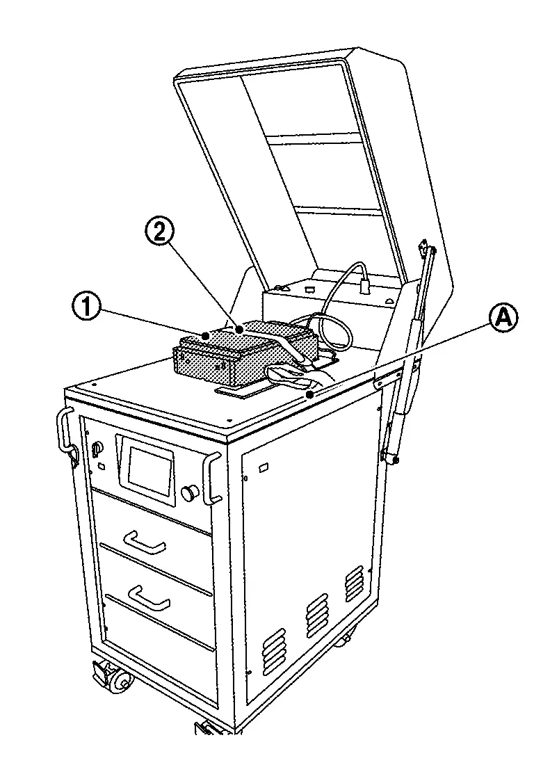
Choose the monitoring cable and connect to the module.
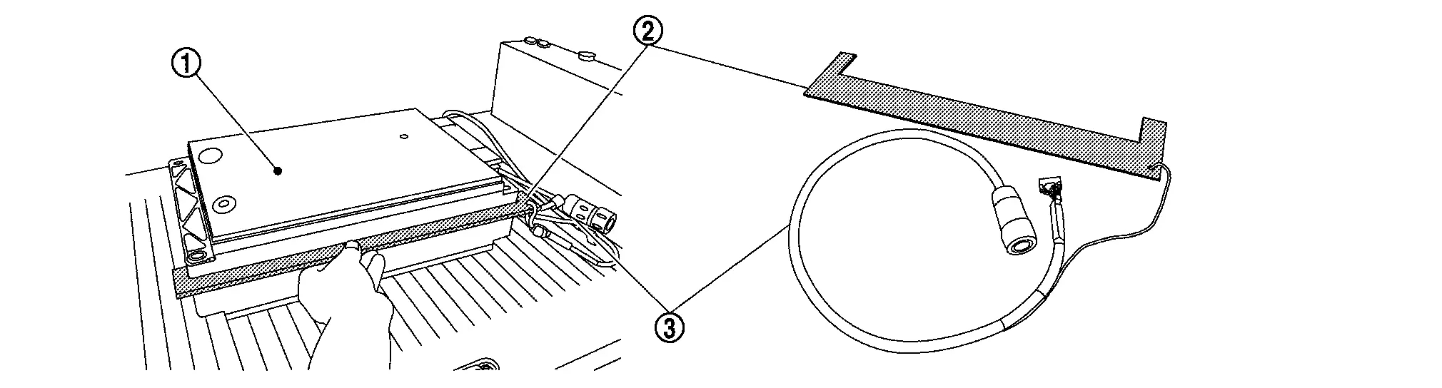 :
Module :Module gauge  :
Monitoring cable ModuleType Monitoring cable No. [Module gauge color] 2P9S (2 Parallel 9 Series) : KV9911-8200 (J-53352) [Blue] 2P6S (2 Parallel 6 Series) : KV9911-8100 (J-53351) [Light gray] Connect the monitoring cable to the module balancer.
Connect the voltage adjustment power cable (+) terminal
and the voltage adjustment power cable (-) to the module.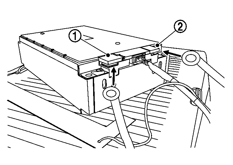
Input “adjustment voltage value” on the module balancer.
ModuleType Adjustment voltage value 2P9S (2 Parallel 9 Series) : Maximum cell voltage× 9 2P6S (2 Parallel 6 Series) : Maximum cell voltage× 6 Example: 3.925 V (Maximum cell voltage) × 9= 35.325 V (Adjustment voltage value)
Start voltage adjustment according to indication of the module balancer.
After module voltage adjustment completion, GO TO 3
CHECK MODULE VOLTAGE
Remove the module from the module charge balancer.
Using a circuit tester, check that the module voltage is within the specified range.
Standard : Adjustment voltage value ± 10 mV
GO TO 4
CHECK CELL VOLTAGE
With CONSULT
After adjusting the voltage, install the module to the Nissan Ariya vehicle.
Select “Data Monitor” of “HIGH VOLTAGE BATTERY”.
Check “Cell voltage” of install module.
Check that the difference from the “Maximum cell voltage” confirmed in Step1 is within the specified range.
Standard : Maximum cell voltage ± 33 mV
WORK END