Basic Inspection

Front Traction Motor System

In this manual: Basic Inspection
How to Use This Manual — 1Precautions — 1Preparation — 1Vehicle Information — 1Basic Inspection — 1Preparation. Commercial Service Tools Or/and Repair Part — 1Description — 1Component Parts — 1System — 1Diagnosis System (vcm) — 1Ecu Diagnosis Information. Vcm — 1Ev Control System — 1Ev/hev (vcm) — 1Component Parts /circuit Diagnosis — 1Ev Control System — 1Periodic Maintenance. Ev System Warning Lamp — 1Removal and Installation. Vcm — 1Traction Motor System :: Front Traction Motor — 1Preparation — 1Description — 4Basic Inspection — 2Dtc Diagnosis — 2Component Parts /circuit Diagnosis — 1Traction Motor System :: Rear Traction Motor — 1Description — 4Basic Inspection — 2Dtc Diagnosis — 2Component Parts /circuit Diagnosis — 1Removal and Installation — 1Ev Battery System :: 66kwh Li-Ion Battery — 1Description — 4Basic Inspection — 2Dtc Diagnosis — 2Component Parts /circuit Diagnosis — 1Removal and Installation — 1Disassembly and Assembly — 2Service Data — 1Ev Battery System :: 91kwh Li-Ion Battery — 1Description — 4Basic Inspection — 2Dtc Diagnosis — 2Component Parts /circuit Diagnosis — 1Removal and Installation — 1Disassembly and Assembly — 1Service Data — 2Preparation. Vehicle Charging System — 1Vehicle Charging System :: Description — 1Component Parts — 2System — 1Diagnosis System (on-Board Charger) — 1Diagnosis System (dc/dc Converter) — 1Ecu Diagnosis Information — 1Vehicle Charging System — 1Charger/pd Module (on-Board Charger) — 1Cplc (cplc) — 1Dcdc (dc/dc Converter) — 1Component Parts/circuit Diagnosis — 1Symptom Diagnosis — 1Evse Inspection — 1Periodic Maintenance — 1Removal and Installation — 1Disassembly and Assembly — 1Preparation. High Voltage Cooling System — 1Description — 1Symptom Diagnosis. Overheating Cause Analysis — 1Periodic Maintenance — 1Coolant — 1Removal and Installation — 1Radiator — 1Service Data — 1Removal and Installation. Accelerator Control System — 1Reduction Gear: Re1f62a — 1Removal and Installation — 1Transaxle & Transmission :: Electric Shift — 1Description — 3Basic Inspection — 2Dtc Diagnosis — 2Component Parts /circuit Diagnosis — 1Removal and Installation — 1Rear Final Drive: Rn1r62a — 1Removal and Installation — 1Preparation. Front Axle System — 1Symptom Diagnosis. Noise, Vibration and Harshness (nvh) Troubleshooting — 1Periodic Maintenance — 1Removal and Installation — 1Service Data. Front Drive Shaft — 12wd — 14wd — 1Periodic Maintenance — 1Removal and Installation — 1Preparation. Front Suspension System — 1Symptom Diagnosis. Noise, Vibration and Harshness (nvh) Troubleshooting — 1Periodic Maintenance — 1Removal and Installation — 1Service Data — 1Symptom Diagnosis. Noise, Vibration and Harshness (nvh) Troubleshooting — 1Periodic Maintenance — 1Removal and Installation — 1Service Data — 1Preparation. Road Wheels & Tires System — 1Description — 1System — 1Ecu Diagnosis Information. Bcm (body Control Module) — 1Tpms — 1Dtc/circuit Diagnosis — 1Symptom Diagnosis — 1Periodic Maintenance. Road Wheels & Tires — 1Removal and Installation — 1Service Data — 1Preparation. Brake System — 1System Description — 1Component Parts — 1Ecu Diagnosis Information. Electrically-Driven Intelligent Brake Unit — 1Basic Inspection — 1Dtc/circuit Diagnosis — 1Symptom Diagnosis — 1Periodic Maintenance — 1Removal and Installation — 1Service Data — 1Preparation. Parking Brake System — 1System Description — 1Component Parts — 1System — 1Ecu Diagnosis Information. Abs Actuator and Electric Unit (control Unit) — 1Basic Inspection. Diagnosis and Repair Work Flow — 1Component Parts /circuit Diagnosis — 1Symptom Diagnosis — 1Removal and Installation — 1Brake Control System :: With Vdc — 1System Description — 3Basic Inspection — 2Dtc/circuit Diagnosis — 1Symptom Diagnosis — 2Removal and Installation — 1Brake Control System :: Automatic Brake Hold — 1System Description — 3Component Parts /circuit Diagnosis — 1Removal and Installation — 1Brake Control System :: E-Step — 1System Description — 3Removal and Installation — 1System Description — 1Ecu Diagnosis Information — 1Basic Inspection — 1Symptom Diagnosis — 1Rear Automatic Braking — 1System Description — 1Basic Inspection — 1Preparation. Steering System — 1System Description — 1Component Parts — 1Basic Inspection — 1Dtc/circuit Diagnosis — 1Symptom Diagnosis — 1Periodic Maintenance. Steering Wheel — 1Removal and Installation — 1Service Data — 1System Description — 1Component Parts — 1Steering Control System — 1Ecu Diagnosis Information. Power Steering Control Module — 1Dtc/circuit Diagnosis — 1Component Parts /circuit Diagnosis — 1Symptom Diagnosis — 1Removal and Installation. Power Steering Control Module — 1System Description — 1Removal and Installation — 1System Description — 1System — 1Basic Inspection. Diagnosis and Repair Work Flow — 1Dtc/circuit Diagnosis — 1Symptom Diagnosis — 1Component Parts — 1Basic Inspection — 1Removal and Installation — 1System Description — 1System — 1Ecu Diagnosis Information. Air Bag Diagnosis Sensor Unit — 1Basic Inspection — 1Dtc/circuit Diagnosis — 1Symptom Diagnosis — 1System Description. Description. Ventilation System — 1Removal and Installation — 1Preparation. Preparation — 1System Description — 1Basic Inspection — 1Symptom Diagnosis — 1Removal and Installation — 1Electric Compressor — 1Cooler Pipe and Hose — 1A/c Unit Assembly Cover — 1A/c Unit Assembly — 1Heater & Air Conditioning Control System :: Automatic Air Conditioning — 1System Description — 1Ecu Diagnosis Information — 1Basic Inspection — 2Dtc Diagnosis — 1Symptom Diagnosis — 1Removal and Installation — 2Preparation. Preparation — 1Symptom Diagnosis. Squeak and Rattle Trouble Diagnoses — 1Removal and Installation — 1Preparation. Instrument Panel — 1Component Parts — 1System — 1Ecu Diagnosis Information. Flexible Center Storage Control Module — 1Basic Inspection. Diagnosis and Repair Work Flow — 1Dtc/circuit Diagnosis — 1Symptom Diagnosis — 1Removal and Installation — 1Preparation. Preparation — 1Component Parts — 1System — 1Ecu Diagnosis Information. Driver Lumbar Support Control Module — 1Basic Inspection. Diagnosis and Repair Work Flow — 1Dtc/circuit Diagnosis — 1Symptom Diagnosis — 1Removal and Installation — 1System Description — 1System — 1Ecu Diagnosis Information — 1Basic Inspection — 1Dtc/circuit Diagnosis — 1Symptom Diagnosis — 1Manual Function Does Not Operate — 1Memory Function Does Not Operate — 1Removal and Installation — 1Preparation. Preparation — 1System Description — 1System (intelligent Key System) — 1Diagnosis System (bcm) — 1Ecu Diagnosis Information — 1Basic Inspection — 1Dtc/circuit Diagnosis — 1U2141-87 Can Comm Circuit — 1Power Supply and Ground Circuit — 1Symptom Diagnosis — 1Automatic Back Door Operation Does Not Operate — 1Back Door Does Not Open — 1Door Does Not Lock/unlock with Door Lock and Unlock Switch — 1Removal and Installation — 1Hood — 1Radiator Core Support — 1Charge Port Lid — 1Front Fender — 1Front Door — 1Rear Door — 1Back Door — 1Hood Lock — 1Front Door Lock — 1Rear Door Lock — 1Back Door Lock — 1Outside Key Antenna — 1System Description — 1System — 1Ecu Diagnosis Information. Inverter (front), Inverter (rear), Bcm, Intelligent Key Unit — 1Basic Inspection — 1Dtc/circuit Diagnosis — 1Symptom Diagnosis — 1Preparation — 1Symptom Diagnosis. Squeak and Rattle Trouble Diagnoses — 1Removal and Installation — 1System Description — 1Ecu Diagnosis Information — 1Basic Inspection — 1Dtc/circuit Diagnosis — 1Power Supply and Ground Circuit — 1Symptom Diagnosis — 1Front Passenger Side Power Window Does Not Operate — 1Rear Lh Side Power Window Does Not Operate — 1Rear Rh Side Power Window Does Not Operate — 1Removal and Installation. Power Window Main Switch — 1Preparation. Preparation — 1System Description — 1Ecu Diagnosis Information — 1Basic Inspection — 1Dtc/circuit Diagnosis — 1Power Supply and Ground Circuit — 1Sunroof Switch Assembly — 1Symptom Diagnosis — 1Auto Operation Does Not Operate — 1Removal and Installation — 1Preparation — 1Description — 1Symptom Diagnosis. Squeak and Rattle Trouble Diagnoses — 1Removal and Installation — 1Service Information — 6Repair Information — 1Precaution — 1Preparation — 1Removal and Installation — 1Service Data — 1Preparation. Preparation — 1Component Parts — 1System — 1Ecu Diagnosis Information — 1Wiring Diagram. Door Mirror — 1Basic Inspection. Diagnosis and Repair Work Flow — 1Dtc/circuit Diagnosis — 1Power Supply and Ground Circuit — 1Symptom Diagnosis — 1Removal and Installation — 1Exterior Lighting System :: Led Headlamp — 1System Description — 3Basic Inspection — 1Dtc/circuit Diagnosis — 1Symptom Diagnosis — 1Periodic Maintenance — 1Removal and Installation — 1System Description — 1System — 1Diagnosis System (bcm) — 1Ecu Diagnosis Information. Bcm, Intelligent Key Unit — 1Basic Inspection. Diagnosis and Repair Work Flow — 1Dtc/circuit Diagnosis — 1Symptom Diagnosis. Interior Lighting System Symptom — 1Removal and Installation — 1Service Data. Bulb Specifications — 1System Description — 1System — 1Ecu Diagnosis Information. Bcm, Ipdm E/r — 1Basic Inspection. Diagnosis and Repair Work Flow — 1Dtc/circuit Diagnosis — 1Symptom Diagnosis — 1Removal and Installation — 1System Description — 1Ecu Diagnosis Information. Bcm — 1Basic Inspection. Diagnosis and Repair Work Flow — 1Dtc/circuit Diagnosis — 1Symptom Diagnosis — 1Removal and Installation — 1Preparation. Preparation — 1Removal and Installation. Horn — 1Preparation. Commercial Service Tools Or/and Repair Part — 1System Description — 1Component Parts — 1Ecu Diagnosis Information. Approaching Vehicle Sound for Pedestrians (vsp) Control Unit — 1Approaching Vehicle Sound for Pedestrians (vsp) — 1Vsp [approaching Vehicle Sound for Pedestrians (vsp) Control Unit] — 1Approaching Vehicle Sound for Pedestrians (vsp) System — 1Removal and Installation — 1Removal and Installation — 1Wireless Charger — 1System Description — 1Basic Inspection — 1Dtc/circuit Diagnosis — 1Removal and Installation — 1Component Parts — 1System — 1Diagnosis System (bcm) — 1Ecu Diagnosis Information. Bcm — 1Basic Inspection — 1Dtc/circuit Diagnosis — 1Symptom Diagnosis — 1Removal and Installation — 1Can Fundamental — 1Description — 1Trouble Diagnosis — 1Can (controller Area Network) — 1Description — 1
25steps
~150min
5/5difficulty
Done 0 of 25
  • Diagnosis and Repair Work Flow
  • Additional Service When Replacing Inverter (front)
  • Writing Resolver Offset Value and Rotor Resistance Value

Diagnosis and Repair Work Flow Nissan Ariya 2026

Diagnostic Work Sheet

DESCRIPTION

By understanding those conditions properly, a quick and exact diagnosis can be achieved.

In general, customers have their own criteria for a problem. Therefore, it is important to understand the symptom and status well enough by asking the customer about the concerns carefully. In order to systemize all the information for the diagnosis, prepare the question sheet referring to the question points.

WORKSHEET SAMPLE

Question Sheet

Customer name

MR/MS

Motor No. Inverter No.
Incident Date VIN
Model & Year In Service Date
Trans. Mileage km/mile
Symptoms □ Does not to READY □ EV system warning lamp is on □ Power limitation indicator lamp is on
□ Water leak* □ Noise* □ Vibration* □ Shock* □ Gear noise*
□ Non driving* □ Poor acceleration* □ Poor torque* □ Radio noise*
□ Does not charge □ Other* *: If applied, enter in detail
Detailed symptom
Onomatopoeia
Frequency □ All the time □ Once □ Sometimes ( times a day) □ Other
Weather conditions □ Not affected
Weather □ Fine □ Clouding □ Raining □ Snowing □ Other ( )
Temp. □ Hot □ Warm □ Cool □ Cold □ Temp. [Approx. °C ( °F)]
Humidity □ High □ Middle □ Low □ Humidity (Approx. %)
Road conditions □ Not affected □ In town □ Freeway □ Off road (Up / Down) □ Deplorable road
□ Flat road □ While turning (Right / Left) □ Bump
□ Other
Shift position □ Not affected
□ P position □ R position □ N position □ D position □ B position
□ ECO mode
Driving conditions □ Not affected
□ Power switch ON → OFF □ Power switch OFF → ON □ READY (stop the Nissan Ariya vehicle)
□ While cruising □ While decelerating □ Just before stopping □ Just after stopping □ D position (stop the Nissan Ariya vehicle)
□ While recharging □ Other
□ Nissan Ariya Vehicle speed [ km/h ( MPH)] □ Accelerator pedal ( / 8)
□ Battery level (Low / Middle / High)
Moments when malfunction disappears □ Disappears while driving □ Disappears when stopped □ Disappears with select operation
□ Disappears when power switch is pushed OFF □ Disappears when battery charge is stopped □ Does not disappear
□ Other
Other

Work Flow

OBTAIN INFORMATION ABOUT SYMPTOM

Refer to Diagnostic Work Sheet and interview the customer to obtain the malfunction information (conditions and environment when the malfunction occurred) as much as possible when the customer brings in the Nissan Ariya vehicle. Refer to Diagnostic Work Sheet.

>>

GO TO 2.

CHECK DTC IN INVERTER (FRONT)

  1. Before checking the malfunction, check whether any DTC exists.

  2. If DTC exists, perform the following operations.

    • Record the DTC and freeze frame data. (Print out the data using CONSULT and affix them to the Work Order Sheet.)

    • Erase DTCs.

    • Check the relationship between the cause that is clarified with DTC and the malfunction information described by the customer.

Do malfunction information and DTC exist?

Malfunction information and DTC exists. >>

GO TO 3.

Malfunction information exists, but no DTC. >>

GO TO 4.

No malfunction information, but DTC exists. >>

GO TO 5.

REPRODUCE MALFUNCTION SYMPTOM

Check any malfunction described by a customer, except those with DTC on the Nissan Ariya vehicle.

Also investigate whether the symptom is a fail-safe or normal operation. Refer to Fail-safe.

When a malfunction symptom is reproduced, the question sheet is effective. Refer to Diagnostic Work Sheet.

Verify the relationship between the symptom and the conditions in which the malfunction described by the customer occurs.

>>

GO TO 5.

REPRODUCE MALFUNCTION SYMPTOM

Check the malfunction described by the customer on the Nissan Ariya vehicle.

Also investigate whether the symptom is a normal operation. Refer to Protection Function.

When a malfunction symptom is reproduced, the question sheet is effective. Refer to Diagnostic Work Sheet.

Verify the relationship between the symptom and the conditions in which the malfunction described by the customer occurs.

>>

GO TO 7.

PERFORM “DTC CONFIRMATION PROCEDURE”

Perform “DTC CONFIRMATION PROCEDURE” of the appropriate DTC to check if DTC is detected again.

Refer to DTC Inspection Priority Chart when multiple DTCs are detected, and then determine the order for performing the diagnosis. Refer to DTC Inspection Priority Chart.

Is any DTC detected?

YES>>

GO TO 6.

NO>>

Check according to Intermittent Incident. Refer to Intermittent Incident.

REPAIR OR REPLACE THE MALFUNCTIONING PARTS

Repair or replace the detected malfunctioning parts.

Reconnect parts or connector after repairing or replacing, and then erase DTC if necessary.

>>

GO TO 7.

FINAL CHECK

Perform “DTC CONFIRMATION PROCEDURE” again to make sure that the repair is correctly performed.

Check that malfunctions are not reproduced when obtaining the malfunction information from the customer, referring to the symptom inspection result in step 3 or 4.

Is DTC or malfunction symptom reproduced?

YES>>

GO TO 2.

NO>>

Before delivering the Nissan Ariya vehicle to the customer, make sure that DTC is erased.

Additional Service When Replacing Inverter (front) Nissan Ariya first Gen

Description

After the inverter (front) are replaced, the following operations need to be conducted. Refer to Work Procedure.

  • Performing recommunication with the intelligent key unit

  • Writing resolver offset value and rotor resistance value

Work Procedure

PERFORMING RECOMMUNICATION WITH THE INTELLIGENT KEY UNIT

Perform recommunication with the intelligent key unit. Refer to Work Procedure.

>>

GO TO 2.

WRITING RESOLVER OFFSET VALUE AND ROTOR RESISTANCE VALUE

Writing resolver offset value and rotor resistance value. Refer to Work Procedure.

>>

WORK END

Writing Resolver Offset Value and Rotor Resistance Value Nissan Ariya first Gen

Description

When one of the following operations is conducted, resolver offset value and rotor resistance value for the front traction motor need to be written into the inverter (front). (For details, refer to Work Procedure.)

  • Replacement of the front traction motor

  • Replacement of the inverter (front)

  • Replacement of the front traction motor and inverter (front)

MARKING POSITION OF THE FRONT TRACTION MOTOR RESOLVER OFFSET VALUE AND ROTOR RESISTANCE VALUE
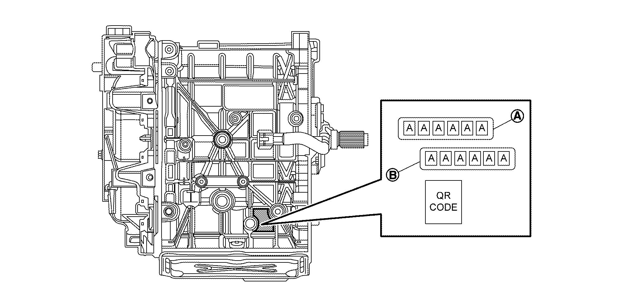
Resolver offset value Rotor resistance value

Work Procedure

CHECK BEFORE WRITING THE OFFSET VALUE AND THE ROTOR RESISTANCE VALUE FOR FRONT TRACTION MOTOR

Check the parts that were replaced.

Which parts were replaced?

Front traction motor>>

GO TO 2.

Inverter (front)>>

GO TO 3.

Front traction motor and inverter (front)>>

GO TO 3.

WRITING THE OFFSET VALUE AND THE ROTOR RESISTANCE VALUE FOR FRONT TRACTION MOTOR

With CONSULT

  1. Power switch ON.

  2. Select "Work support" under "MOTOR CONTROL".

  3. Select "Writing Resolver Offset Value and Rotor Resistance Value".

  4. Enter the resolver offset value and rotor resistance value that are printed on the front traction motor into the "Write value of resolver offset value and rotor resistance value" field.

  5. Touch "Write".

Is "Writing is complete." displayed?

YES>>
  1. Power switch OFF.

  2. Power switch ON and wait at least 2 seconds.

  3. Check that the value input in "Writing Resolver Offset Value and Rotor Resistance Value" has been applied.

  4. Power switch OFF and finish the task.

NO>>

Perform Step 2 again.

WRITING THE OFFSET VALUE AND THE ROTOR RESISTANCE VALUE FOR FRONT TRACTION MOTOR

With CONSULT

  1. Power switch ON.

  2. Select "Work support" under "MOTOR CONTROL".

  3. Select "Writing Resolver Offset Value and Rotor Resistance Value".

  4. Enter the resolver offset value and rotor resistance value that are printed on the front traction motor into the "Write value of resolver offset value and rotor resistance value" field.

  5. Touch "Write".

Is "Writing is complete." displayed?

YES>>

GO TO 4.

NO>>

Perform Step 3 again.

WORK AFTER WRITING THE OFFSET VALUE AND THE ROTOR RESISTANCE VALUE FOR FRONT TRACTION MOTOR

With CONSULT

  1. Power switch OFF.

  2. Power switch ON and wait at least 2 seconds.

  3. Check that the EV system warning lamp turns OFF.

  4. Select "Work support" under "MOTOR CONTROL".

  5. Select "Writing Resolver Offset Value and Rotor Resistance Value".

  6. Check that "Current resolver offset value and rotor resistance value" has changed to the value that was input.

  7. Select "Self Diagnostic Result" under "MOTOR CONTROL".

  8. Clear DTC "P3081-44" and "P3082-44".

  9. Power switch OFF.

>>

WORK END