Basic Inspection

Heater & Air Conditioning Control System

In this manual: Basic Inspection
How to Use This Manual — 1Precautions — 1Preparation — 1Vehicle Information — 1Basic Inspection — 1Preparation. Commercial Service Tools Or/and Repair Part — 1Description — 1Component Parts — 1System — 1Diagnosis System (vcm) — 1Ecu Diagnosis Information. Vcm — 1Ev Control System — 1Ev/hev (vcm) — 1Component Parts /circuit Diagnosis — 1Ev Control System — 1Periodic Maintenance. Ev System Warning Lamp — 1Removal and Installation. Vcm — 1Traction Motor System :: Front Traction Motor — 1Preparation — 1Description — 4Basic Inspection — 2Dtc Diagnosis — 2Component Parts /circuit Diagnosis — 1Traction Motor System :: Rear Traction Motor — 1Description — 4Basic Inspection — 2Dtc Diagnosis — 2Component Parts /circuit Diagnosis — 1Removal and Installation — 1Ev Battery System :: 66kwh Li-Ion Battery — 1Description — 4Basic Inspection — 2Dtc Diagnosis — 2Component Parts /circuit Diagnosis — 1Removal and Installation — 1Disassembly and Assembly — 2Service Data — 1Ev Battery System :: 91kwh Li-Ion Battery — 1Description — 4Basic Inspection — 2Dtc Diagnosis — 2Component Parts /circuit Diagnosis — 1Removal and Installation — 1Disassembly and Assembly — 1Service Data — 2Preparation. Vehicle Charging System — 1Vehicle Charging System :: Description — 1Component Parts — 2System — 1Diagnosis System (on-Board Charger) — 1Diagnosis System (dc/dc Converter) — 1Ecu Diagnosis Information — 1Vehicle Charging System — 1Charger/pd Module (on-Board Charger) — 1Cplc (cplc) — 1Dcdc (dc/dc Converter) — 1Component Parts/circuit Diagnosis — 1Symptom Diagnosis — 1Evse Inspection — 1Periodic Maintenance — 1Removal and Installation — 1Disassembly and Assembly — 1Preparation. High Voltage Cooling System — 1Description — 1Symptom Diagnosis. Overheating Cause Analysis — 1Periodic Maintenance — 1Coolant — 1Removal and Installation — 1Radiator — 1Service Data — 1Removal and Installation. Accelerator Control System — 1Reduction Gear: Re1f62a — 1Removal and Installation — 1Transaxle & Transmission :: Electric Shift — 1Description — 3Basic Inspection — 2Dtc Diagnosis — 2Component Parts /circuit Diagnosis — 1Removal and Installation — 1Rear Final Drive: Rn1r62a — 1Removal and Installation — 1Preparation. Front Axle System — 1Symptom Diagnosis. Noise, Vibration and Harshness (nvh) Troubleshooting — 1Periodic Maintenance — 1Removal and Installation — 1Service Data. Front Drive Shaft — 12wd — 14wd — 1Periodic Maintenance — 1Removal and Installation — 1Preparation. Front Suspension System — 1Symptom Diagnosis. Noise, Vibration and Harshness (nvh) Troubleshooting — 1Periodic Maintenance — 1Removal and Installation — 1Service Data — 1Symptom Diagnosis. Noise, Vibration and Harshness (nvh) Troubleshooting — 1Periodic Maintenance — 1Removal and Installation — 1Service Data — 1Preparation. Road Wheels & Tires System — 1Description — 1System — 1Ecu Diagnosis Information. Bcm (body Control Module) — 1Tpms — 1Dtc/circuit Diagnosis — 1Symptom Diagnosis — 1Periodic Maintenance. Road Wheels & Tires — 1Removal and Installation — 1Service Data — 1Preparation. Brake System — 1System Description — 1Component Parts — 1Ecu Diagnosis Information. Electrically-Driven Intelligent Brake Unit — 1Basic Inspection — 1Dtc/circuit Diagnosis — 1Symptom Diagnosis — 1Periodic Maintenance — 1Removal and Installation — 1Service Data — 1Preparation. Parking Brake System — 1System Description — 1Component Parts — 1System — 1Ecu Diagnosis Information. Abs Actuator and Electric Unit (control Unit) — 1Basic Inspection. Diagnosis and Repair Work Flow — 1Component Parts /circuit Diagnosis — 1Symptom Diagnosis — 1Removal and Installation — 1Brake Control System :: With Vdc — 1System Description — 3Basic Inspection — 2Dtc/circuit Diagnosis — 1Symptom Diagnosis — 2Removal and Installation — 1Brake Control System :: Automatic Brake Hold — 1System Description — 3Component Parts /circuit Diagnosis — 1Removal and Installation — 1Brake Control System :: E-Step — 1System Description — 3Removal and Installation — 1System Description — 1Ecu Diagnosis Information — 1Basic Inspection — 1Symptom Diagnosis — 1Rear Automatic Braking — 1System Description — 1Basic Inspection — 1Preparation. Steering System — 1System Description — 1Component Parts — 1Basic Inspection — 1Dtc/circuit Diagnosis — 1Symptom Diagnosis — 1Periodic Maintenance. Steering Wheel — 1Removal and Installation — 1Service Data — 1System Description — 1Component Parts — 1Steering Control System — 1Ecu Diagnosis Information. Power Steering Control Module — 1Dtc/circuit Diagnosis — 1Component Parts /circuit Diagnosis — 1Symptom Diagnosis — 1Removal and Installation. Power Steering Control Module — 1System Description — 1Removal and Installation — 1System Description — 1System — 1Basic Inspection. Diagnosis and Repair Work Flow — 1Dtc/circuit Diagnosis — 1Symptom Diagnosis — 1Component Parts — 1Basic Inspection — 1Removal and Installation — 1System Description — 1System — 1Ecu Diagnosis Information. Air Bag Diagnosis Sensor Unit — 1Basic Inspection — 1Dtc/circuit Diagnosis — 1Symptom Diagnosis — 1System Description. Description. Ventilation System — 1Removal and Installation — 1Preparation. Preparation — 1System Description — 1Basic Inspection — 1Symptom Diagnosis — 1Removal and Installation — 1Electric Compressor — 1Cooler Pipe and Hose — 1A/c Unit Assembly Cover — 1A/c Unit Assembly — 1Heater & Air Conditioning Control System :: Automatic Air Conditioning — 1System Description — 1Ecu Diagnosis Information — 1Basic Inspection — 2Dtc Diagnosis — 1Symptom Diagnosis — 1Removal and Installation — 2Preparation. Preparation — 1Symptom Diagnosis. Squeak and Rattle Trouble Diagnoses — 1Removal and Installation — 1Preparation. Instrument Panel — 1Component Parts — 1System — 1Ecu Diagnosis Information. Flexible Center Storage Control Module — 1Basic Inspection. Diagnosis and Repair Work Flow — 1Dtc/circuit Diagnosis — 1Symptom Diagnosis — 1Removal and Installation — 1Preparation. Preparation — 1Component Parts — 1System — 1Ecu Diagnosis Information. Driver Lumbar Support Control Module — 1Basic Inspection. Diagnosis and Repair Work Flow — 1Dtc/circuit Diagnosis — 1Symptom Diagnosis — 1Removal and Installation — 1System Description — 1System — 1Ecu Diagnosis Information — 1Basic Inspection — 1Dtc/circuit Diagnosis — 1Symptom Diagnosis — 1Manual Function Does Not Operate — 1Memory Function Does Not Operate — 1Removal and Installation — 1Preparation. Preparation — 1System Description — 1System (intelligent Key System) — 1Diagnosis System (bcm) — 1Ecu Diagnosis Information — 1Basic Inspection — 1Dtc/circuit Diagnosis — 1U2141-87 Can Comm Circuit — 1Power Supply and Ground Circuit — 1Symptom Diagnosis — 1Automatic Back Door Operation Does Not Operate — 1Back Door Does Not Open — 1Door Does Not Lock/unlock with Door Lock and Unlock Switch — 1Removal and Installation — 1Hood — 1Radiator Core Support — 1Charge Port Lid — 1Front Fender — 1Front Door — 1Rear Door — 1Back Door — 1Hood Lock — 1Front Door Lock — 1Rear Door Lock — 1Back Door Lock — 1Outside Key Antenna — 1System Description — 1System — 1Ecu Diagnosis Information. Inverter (front), Inverter (rear), Bcm, Intelligent Key Unit — 1Basic Inspection — 1Dtc/circuit Diagnosis — 1Symptom Diagnosis — 1Preparation — 1Symptom Diagnosis. Squeak and Rattle Trouble Diagnoses — 1Removal and Installation — 1System Description — 1Ecu Diagnosis Information — 1Basic Inspection — 1Dtc/circuit Diagnosis — 1Power Supply and Ground Circuit — 1Symptom Diagnosis — 1Front Passenger Side Power Window Does Not Operate — 1Rear Lh Side Power Window Does Not Operate — 1Rear Rh Side Power Window Does Not Operate — 1Removal and Installation. Power Window Main Switch — 1Preparation. Preparation — 1System Description — 1Ecu Diagnosis Information — 1Basic Inspection — 1Dtc/circuit Diagnosis — 1Power Supply and Ground Circuit — 1Sunroof Switch Assembly — 1Symptom Diagnosis — 1Auto Operation Does Not Operate — 1Removal and Installation — 1Preparation — 1Description — 1Symptom Diagnosis. Squeak and Rattle Trouble Diagnoses — 1Removal and Installation — 1Service Information — 6Repair Information — 1Precaution — 1Preparation — 1Removal and Installation — 1Service Data — 1Preparation. Preparation — 1Component Parts — 1System — 1Ecu Diagnosis Information — 1Wiring Diagram. Door Mirror — 1Basic Inspection. Diagnosis and Repair Work Flow — 1Dtc/circuit Diagnosis — 1Power Supply and Ground Circuit — 1Symptom Diagnosis — 1Removal and Installation — 1Exterior Lighting System :: Led Headlamp — 1System Description — 3Basic Inspection — 1Dtc/circuit Diagnosis — 1Symptom Diagnosis — 1Periodic Maintenance — 1Removal and Installation — 1System Description — 1System — 1Diagnosis System (bcm) — 1Ecu Diagnosis Information. Bcm, Intelligent Key Unit — 1Basic Inspection. Diagnosis and Repair Work Flow — 1Dtc/circuit Diagnosis — 1Symptom Diagnosis. Interior Lighting System Symptom — 1Removal and Installation — 1Service Data. Bulb Specifications — 1System Description — 1System — 1Ecu Diagnosis Information. Bcm, Ipdm E/r — 1Basic Inspection. Diagnosis and Repair Work Flow — 1Dtc/circuit Diagnosis — 1Symptom Diagnosis — 1Removal and Installation — 1System Description — 1Ecu Diagnosis Information. Bcm — 1Basic Inspection. Diagnosis and Repair Work Flow — 1Dtc/circuit Diagnosis — 1Symptom Diagnosis — 1Removal and Installation — 1Preparation. Preparation — 1Removal and Installation. Horn — 1Preparation. Commercial Service Tools Or/and Repair Part — 1System Description — 1Component Parts — 1Ecu Diagnosis Information. Approaching Vehicle Sound for Pedestrians (vsp) Control Unit — 1Approaching Vehicle Sound for Pedestrians (vsp) — 1Vsp [approaching Vehicle Sound for Pedestrians (vsp) Control Unit] — 1Approaching Vehicle Sound for Pedestrians (vsp) System — 1Removal and Installation — 1Removal and Installation — 1Wireless Charger — 1System Description — 1Basic Inspection — 1Dtc/circuit Diagnosis — 1Removal and Installation — 1Component Parts — 1System — 1Diagnosis System (bcm) — 1Ecu Diagnosis Information. Bcm — 1Basic Inspection — 1Dtc/circuit Diagnosis — 1Symptom Diagnosis — 1Removal and Installation — 1Can Fundamental — 1Description — 1Trouble Diagnosis — 1Can (controller Area Network) — 1Description — 1
48steps
~288min
5/5difficulty
Done 0 of 48
  • Diagnosis and Repair Work Flow
  • Electric Expansion Initialize
  • Operation Inspection (automatic Air Conditioning System)
  • Additional Service When Replacing A/c Auto Amp.
  • Configuration (a/c Auto Amp.)

Diagnosis and Repair Work Flow Nissan Ariya 1st generation

Work Flow

OVERALL SEQUENCE
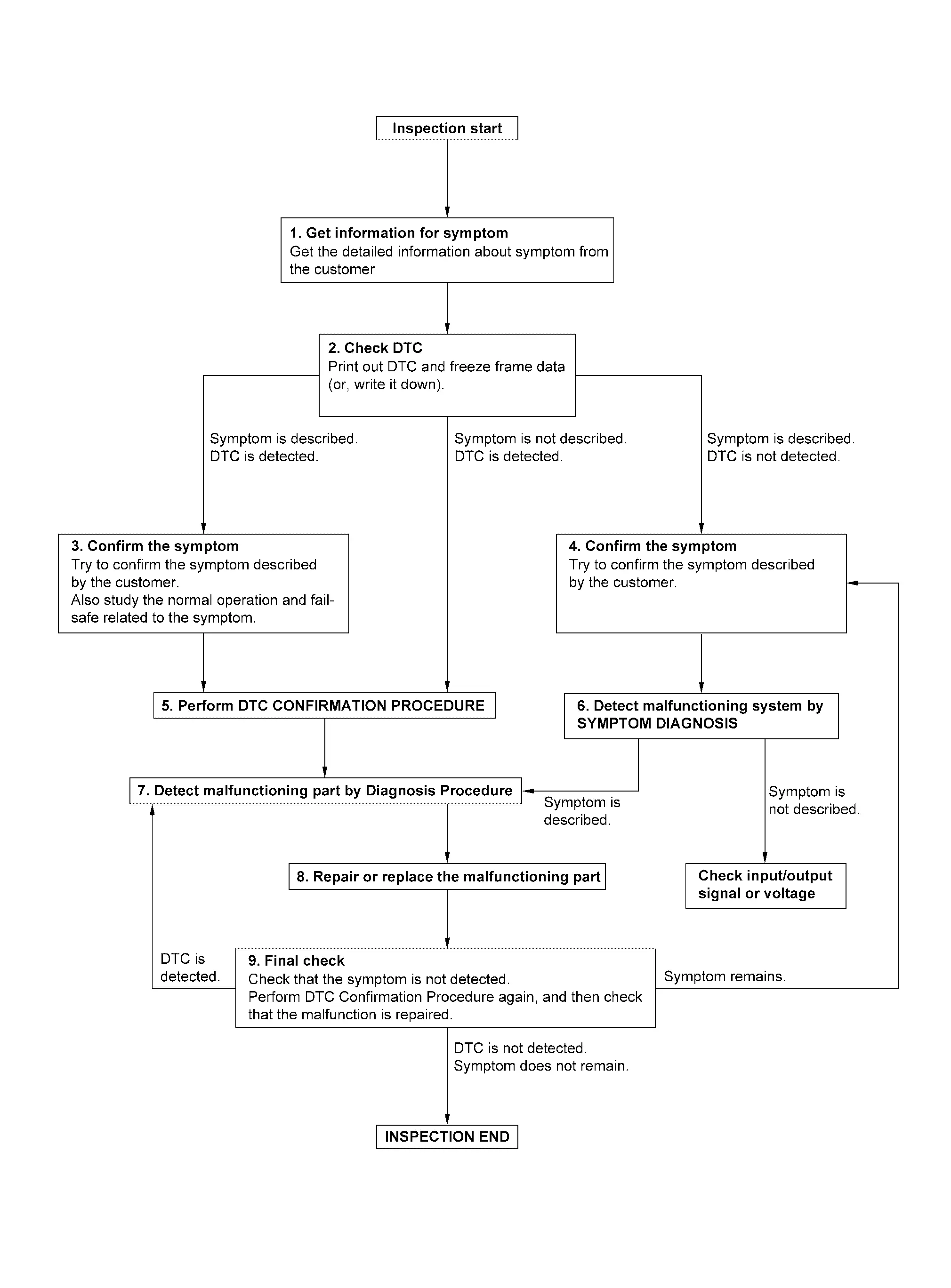
DETAILED FLOW

GET INFORMATION FOR SYMPTOM

  1. Get detailed information from the customer about the symptom (the condition and the environment when the incident/malfunction occurs).

  2. Check operation condition of the function that is malfunctioning.

>>

GO TO 2.

CHECK DTC

  1. Check DTC.

  2. Perform the following procedure if DTC is detected.

    • Record DTC and freeze frame data (Print them out using CONSULT.)

    • Erase DTC.

    • Study the relationship between the cause detected by DTC and the symptom described by the customer.

Are any symptoms described and any DTC detected?

Symptom is described, DTC is detected>>

GO TO 3.

Symptom is described, DTC is not detected>>

GO TO 4.

Symptom is not described, DTC is detected>>

GO TO 5.

CONFIRM THE SYMPTOM

Try to confirm the symptom described by the customer.

Also study the normal operation and fail-safe related to the symptom.

Verify relation between the symptom and the condition when the symptom is detected.

>>

GO TO 5.

CONFIRM THE SYMPTOM

Try to confirm the symptom described by the customer.

Verify relation between the symptom and the condition when the symptom is detected.

>>

GO TO 6.

PERFORM DTC CONFIRMATION PROCEDURE

Perform DTC CONFIRMATION PROCEDURE for the detected DTC, and then check that DTC is detected again. At this time, always connect CONSULT to the Nissan Ariya vehicle, and check self diagnostic results in real time.

If two or more DTCs are detected, refer to DTC INSPECTION PRIORITY CHART, and determine trouble diagnosis order.

Is DTC detected?

YES>>

GO TO 7.

NO>>

Check according to Intermittent Incident. Refer to Intermittent Incident.

DETECT MALFUNCTIONING SYSTEM BY SYMPTOM DIAGNOSIS

Detect malfunctioning system according to SYMPTOM DIAGNOSIS based on the confirmed symptom in step 4, and determine the trouble diagnosis order based on possible causes and symptom.

Is the symptom described?

YES>>

GO TO 7.

NO>>

Monitor input data from related sensors or check voltage of related module terminals using CONSULT.

DETECT MALFUNCTIONING PART BY DIAGNOSIS PROCEDURE

Inspect according to Diagnosis Procedure of the system.

Is malfunctioning part detected?

YES>>

GO TO 8.

NO>>

Check according to Intermittent Incident. Refer to Intermittent Incident.

REPAIR OR REPLACE THE MALFUNCTIONING PART

  1. Repair or replace the malfunctioning part.

  2. Reconnect parts or connectors disconnected during Diagnosis Procedure again after repair and replacement.

  3. Check DTC. If DTC is detected, erase it.

>>

GO TO 9.

FINAL CHECK

When DTC is detected in step 2, perform DTC CONFIRMATION PROCEDURE again, and then check that the malfunction is repaired securely.

When symptom is described by the customer, refer to confirmed symptom in step 3 or 4, and check that the symptom is not detected.

Is DTC detected and does symptom remain?

YES-1>>

DTC is detected: GO TO 7.

YES-2>>

Symptom remains: GO TO 4.

NO>>

Before returning the Nissan Ariya vehicle to the customer, always erase DTC.

Electric Expansion Initialize Nissan Ariya SUV

Work Procedure

If electric expansion valve (cooler), electric expansion valve (heater) or expansion valve (battery chiller) is removed, it is necessary to perform electric expansion initialize using CONSULT.

PERFORM ELECTRIC EXPANSION INITIALIZE

With CONSULT

  1. Power switch ON.

  2. Select “Electric expansion initialize” in “Active Test” mode of “HEAT PUMP CONTROL” using CONSULT.

  3. Touch “START” and wait for a few seconds.

  4. Check that "electric expansion initialize" of "Data Monitor" of "HEAT PUMP CONTROL" is displayed as "Done".

>>

INSPECTION END

Operation Inspection (automatic Air Conditioning System) Nissan Ariya

Work Procedure

DESCRIPTION

The purpose of the operation inspection is to check that the individual system operates normally.

OPERATION INSPECTION

CHECK MEMORY FUNCTION

  1. Set the vehicle to READY.

  2. Activate air conditioning.

  3. Set temperature to "HI" by operating temperature control switch (driver side).

  4. Touch ON·OFF switch.

  5. Power switch OFF.

  6. Power switch ON.

  7. Touch AUTO switch.

  8. Check that the set temperature "HI" is maintained.

Is the inspection result normal?

YES>>

GO TO 2.

NO>>

GO TO 10.

CHECK FAN SPEED

  1. Set the Nissan Ariya vehicle to READY.

  2. Operate fan switch and check that fan speed changes.

  3. Check operation for all fan speeds.

Is the inspection result normal?

YES>>

GO TO 3.

NO>>

GO TO 10.

CHECK AIR OUTLET

  1. Operate fan switch to set the fan speed to maximum speed.

  2. Operate MODE switch and DEF switch.

  3. Check that air outlets change according to each indicated air outlet by placing a hand in front of the outlets. Refer to System Description.

Is the inspection result normal?

YES>>

GO TO 4.

NO>>

GO TO 10.

CHECK AIR INLET

  1. Touch intake switch to set the air inlet to recirculation. The intake switch indicator color turns orange.

  2. Listen to intake sound and confirm air inlets change.

  3. Touch intake switch again to set the air inlet to fresh air intake. The intake switch indicator color turns white.

  4. Listen to intake sound and confirm air inlets change.

Is the inspection result normal?

YES>>

GO TO 5.

NO>>

GO TO 10.

CHECK ELECTRIC COMPRESSOR

  1. Touch A/C switch. The A/C switch indicator color turns orange.

  2. Check by sound that the electric compressor operates.

  3. Touch A/C switch again. The A/C switch indicator color turns white.

  4. Check that compressor stops.

Is the inspection result normal?

YES>>

GO TO 6.

NO>>

GO TO 10.

CHECK DISCHARGE AIR TEMPERATURE

  1. Operate temperature control switch (driver side).

  2. Check that discharge air temperature (driver side) changes.

  3. Operate temperature control switch (passenger side).

  4. Check that discharge air temperature (passenger side) changes.

  5. Touch SYNC switch. SYNC switch indicator color turns orange.

  6. Check that air temperature setting (driver side/passenger side) is unified to the driver side temperature setting.

Is the inspection result normal?

YES>>

GO TO 7.

NO>>

GO TO 10.

CHECK WITH TEMPERATURE SETTING LOWERED

  1. Operate electric compressor.

  2. Operate temperature control switch (driver side) to lower the set temperature to "LO".

  3. Check that cool air blows from the air outlets.

Is the inspection result normal?

YES>>

GO TO 8.

NO>>

GO TO 10.

CHECK TEMPERATURE INCREASE

  1. Operate temperature control switch (driver side) to raise the set temperature to "HI".

  2. Check that warm air blows from the air outlets.

Is the inspection result normal?

YES>>

GO TO 9.

NO>>

GO TO 10.

CHECK AUTO MODE

  1. Touch AUTO switch and check that AUTO indicator color turns orange.

  2. Operate temperature control switch (driver side) to check that fan speed or air outlet changes (the air outlet or fan speed varies depending on the ambient temperature, in-Nissan Ariya vehicle temperature, set temperature, and etc.).

Is the inspection result normal?

YES>>

GO TO 10.

NO>>

GO TO 11.

CHECK SELF-DIAGNOSIS WITH CONSULT

  1. Perform self-diagnosis with CONSULT.

  2. Check that any DTC is detected.

Is any DTC detected?

YES>>

Perform the appropriate diagnosis. Refer to DTC Index.

NO>>

GO TO 11.

CHECK FAIL-SAFE ACTIVATION

Check that symptom is applied to the fail-safe activation. Refer to Fail-safe.

>>

Perform the appropriate diagnosis. Refer to Symptom Table.

Additional Service When Replacing A/c Auto Amp. Nissan Ariya 2026

Work Procedure

After replaced A/C auto amp. it is necessary to perform control unit configuration with CONSULT.

AFTER REPLACEMENT

REPLACE A/C AUTO AMP.

Replace A/C auto amp. Refer to Removal & Installation.

>>

GO TO 2.

WRITING Nissan Ariya Vehicle SPECIFICATION

Perform configuration (A/C auto amp.). Refer to Work Procedure.

>>

WORK END

Configuration (a/c Auto Amp.) Nissan Ariya first Gen

Work Procedure

Vehicle specification needs to be written with CONSULT because it is not written after replacing the A/C auto amp.

CONSULT connects to network and then it downloads the configuration data from the server. Then CONSULT writes the Nissan Ariya vehicle specification to the A/C auto amp.

WRITING VEHICLE SPECIFICATION

With CONSULT

Perform writing Nissan Ariya vehicle specification to A/C auto amp. according to "Replace ECU" in “CONSULT Operation Manual”.

>>

WORK END