System Description

System

In this manual: System Description
How to Use This Manual — 1Precautions — 1Preparation — 1Vehicle Information — 1Basic Inspection — 1Preparation. Commercial Service Tools Or/and Repair Part — 1Description — 1Component Parts — 1System — 1Diagnosis System (vcm) — 1Ecu Diagnosis Information. Vcm — 1Ev Control System — 1Ev/hev (vcm) — 1Component Parts /circuit Diagnosis — 1Ev Control System — 1Periodic Maintenance. Ev System Warning Lamp — 1Removal and Installation. Vcm — 1Traction Motor System :: Front Traction Motor — 1Preparation — 1Description — 4Basic Inspection — 2Dtc Diagnosis — 2Component Parts /circuit Diagnosis — 1Traction Motor System :: Rear Traction Motor — 1Description — 4Basic Inspection — 2Dtc Diagnosis — 2Component Parts /circuit Diagnosis — 1Removal and Installation — 1Ev Battery System :: 66kwh Li-Ion Battery — 1Description — 4Basic Inspection — 2Dtc Diagnosis — 2Component Parts /circuit Diagnosis — 1Removal and Installation — 1Disassembly and Assembly — 2Service Data — 1Ev Battery System :: 91kwh Li-Ion Battery — 1Description — 4Basic Inspection — 2Dtc Diagnosis — 2Component Parts /circuit Diagnosis — 1Removal and Installation — 1Disassembly and Assembly — 1Service Data — 2Preparation. Vehicle Charging System — 1Vehicle Charging System :: Description — 1Component Parts — 2System — 1Diagnosis System (on-Board Charger) — 1Diagnosis System (dc/dc Converter) — 1Ecu Diagnosis Information — 1Vehicle Charging System — 1Charger/pd Module (on-Board Charger) — 1Cplc (cplc) — 1Dcdc (dc/dc Converter) — 1Component Parts/circuit Diagnosis — 1Symptom Diagnosis — 1Evse Inspection — 1Periodic Maintenance — 1Removal and Installation — 1Disassembly and Assembly — 1Preparation. High Voltage Cooling System — 1Description — 1Symptom Diagnosis. Overheating Cause Analysis — 1Periodic Maintenance — 1Coolant — 1Removal and Installation — 1Radiator — 1Service Data — 1Removal and Installation. Accelerator Control System — 1Reduction Gear: Re1f62a — 1Removal and Installation — 1Transaxle & Transmission :: Electric Shift — 1Description — 3Basic Inspection — 2Dtc Diagnosis — 2Component Parts /circuit Diagnosis — 1Removal and Installation — 1Rear Final Drive: Rn1r62a — 1Removal and Installation — 1Preparation. Front Axle System — 1Symptom Diagnosis. Noise, Vibration and Harshness (nvh) Troubleshooting — 1Periodic Maintenance — 1Removal and Installation — 1Service Data. Front Drive Shaft — 12wd — 14wd — 1Periodic Maintenance — 1Removal and Installation — 1Preparation. Front Suspension System — 1Symptom Diagnosis. Noise, Vibration and Harshness (nvh) Troubleshooting — 1Periodic Maintenance — 1Removal and Installation — 1Service Data — 1Symptom Diagnosis. Noise, Vibration and Harshness (nvh) Troubleshooting — 1Periodic Maintenance — 1Removal and Installation — 1Service Data — 1Preparation. Road Wheels & Tires System — 1Description — 1System — 1Ecu Diagnosis Information. Bcm (body Control Module) — 1Tpms — 1Dtc/circuit Diagnosis — 1Symptom Diagnosis — 1Periodic Maintenance. Road Wheels & Tires — 1Removal and Installation — 1Service Data — 1Preparation. Brake System — 1System Description — 1Component Parts — 1Ecu Diagnosis Information. Electrically-Driven Intelligent Brake Unit — 1Basic Inspection — 1Dtc/circuit Diagnosis — 1Symptom Diagnosis — 1Periodic Maintenance — 1Removal and Installation — 1Service Data — 1Preparation. Parking Brake System — 1System Description — 1Component Parts — 1System — 1Ecu Diagnosis Information. Abs Actuator and Electric Unit (control Unit) — 1Basic Inspection. Diagnosis and Repair Work Flow — 1Component Parts /circuit Diagnosis — 1Symptom Diagnosis — 1Removal and Installation — 1Brake Control System :: With Vdc — 1System Description — 3Basic Inspection — 2Dtc/circuit Diagnosis — 1Symptom Diagnosis — 2Removal and Installation — 1Brake Control System :: Automatic Brake Hold — 1System Description — 3Component Parts /circuit Diagnosis — 1Removal and Installation — 1Brake Control System :: E-Step — 1System Description — 3Removal and Installation — 1System Description — 1Ecu Diagnosis Information — 1Basic Inspection — 1Symptom Diagnosis — 1Rear Automatic Braking — 1System Description — 1Basic Inspection — 1Preparation. Steering System — 1System Description — 1Component Parts — 1Basic Inspection — 1Dtc/circuit Diagnosis — 1Symptom Diagnosis — 1Periodic Maintenance. Steering Wheel — 1Removal and Installation — 1Service Data — 1System Description — 1Component Parts — 1Steering Control System — 1Ecu Diagnosis Information. Power Steering Control Module — 1Dtc/circuit Diagnosis — 1Component Parts /circuit Diagnosis — 1Symptom Diagnosis — 1Removal and Installation. Power Steering Control Module — 1System Description — 1Removal and Installation — 1System Description — 1System — 1Basic Inspection. Diagnosis and Repair Work Flow — 1Dtc/circuit Diagnosis — 1Symptom Diagnosis — 1Component Parts — 1Basic Inspection — 1Removal and Installation — 1System Description — 1System — 1Ecu Diagnosis Information. Air Bag Diagnosis Sensor Unit — 1Basic Inspection — 1Dtc/circuit Diagnosis — 1Symptom Diagnosis — 1System Description. Description. Ventilation System — 1Removal and Installation — 1Preparation. Preparation — 1System Description — 1Basic Inspection — 1Symptom Diagnosis — 1Removal and Installation — 1Electric Compressor — 1Cooler Pipe and Hose — 1A/c Unit Assembly Cover — 1A/c Unit Assembly — 1Heater & Air Conditioning Control System :: Automatic Air Conditioning — 1System Description — 1Ecu Diagnosis Information — 1Basic Inspection — 2Dtc Diagnosis — 1Symptom Diagnosis — 1Removal and Installation — 2Preparation. Preparation — 1Symptom Diagnosis. Squeak and Rattle Trouble Diagnoses — 1Removal and Installation — 1Preparation. Instrument Panel — 1Component Parts — 1System — 1Ecu Diagnosis Information. Flexible Center Storage Control Module — 1Basic Inspection. Diagnosis and Repair Work Flow — 1Dtc/circuit Diagnosis — 1Symptom Diagnosis — 1Removal and Installation — 1Preparation. Preparation — 1Component Parts — 1System — 1Ecu Diagnosis Information. Driver Lumbar Support Control Module — 1Basic Inspection. Diagnosis and Repair Work Flow — 1Dtc/circuit Diagnosis — 1Symptom Diagnosis — 1Removal and Installation — 1System Description — 1System — 1Ecu Diagnosis Information — 1Basic Inspection — 1Dtc/circuit Diagnosis — 1Symptom Diagnosis — 1Manual Function Does Not Operate — 1Memory Function Does Not Operate — 1Removal and Installation — 1Preparation. Preparation — 1System Description — 1System (intelligent Key System) — 1Diagnosis System (bcm) — 1Ecu Diagnosis Information — 1Basic Inspection — 1Dtc/circuit Diagnosis — 1U2141-87 Can Comm Circuit — 1Power Supply and Ground Circuit — 1Symptom Diagnosis — 1Automatic Back Door Operation Does Not Operate — 1Back Door Does Not Open — 1Door Does Not Lock/unlock with Door Lock and Unlock Switch — 1Removal and Installation — 1Hood — 1Radiator Core Support — 1Charge Port Lid — 1Front Fender — 1Front Door — 1Rear Door — 1Back Door — 1Hood Lock — 1Front Door Lock — 1Rear Door Lock — 1Back Door Lock — 1Outside Key Antenna — 1System Description — 1System — 1Ecu Diagnosis Information. Inverter (front), Inverter (rear), Bcm, Intelligent Key Unit — 1Basic Inspection — 1Dtc/circuit Diagnosis — 1Symptom Diagnosis — 1Preparation — 1Symptom Diagnosis. Squeak and Rattle Trouble Diagnoses — 1Removal and Installation — 1System Description — 1Ecu Diagnosis Information — 1Basic Inspection — 1Dtc/circuit Diagnosis — 1Power Supply and Ground Circuit — 1Symptom Diagnosis — 1Front Passenger Side Power Window Does Not Operate — 1Rear Lh Side Power Window Does Not Operate — 1Rear Rh Side Power Window Does Not Operate — 1Removal and Installation. Power Window Main Switch — 1Preparation. Preparation — 1System Description — 1Ecu Diagnosis Information — 1Basic Inspection — 1Dtc/circuit Diagnosis — 1Power Supply and Ground Circuit — 1Sunroof Switch Assembly — 1Symptom Diagnosis — 1Auto Operation Does Not Operate — 1Removal and Installation — 1Preparation — 1Description — 1Symptom Diagnosis. Squeak and Rattle Trouble Diagnoses — 1Removal and Installation — 1Service Information — 6Repair Information — 1Precaution — 1Preparation — 1Removal and Installation — 1Service Data — 1Preparation. Preparation — 1Component Parts — 1System — 1Ecu Diagnosis Information — 1Wiring Diagram. Door Mirror — 1Basic Inspection. Diagnosis and Repair Work Flow — 1Dtc/circuit Diagnosis — 1Power Supply and Ground Circuit — 1Symptom Diagnosis — 1Removal and Installation — 1Exterior Lighting System :: Led Headlamp — 1System Description — 3Basic Inspection — 1Dtc/circuit Diagnosis — 1Symptom Diagnosis — 1Periodic Maintenance — 1Removal and Installation — 1System Description — 1System — 1Diagnosis System (bcm) — 1Ecu Diagnosis Information. Bcm, Intelligent Key Unit — 1Basic Inspection. Diagnosis and Repair Work Flow — 1Dtc/circuit Diagnosis — 1Symptom Diagnosis. Interior Lighting System Symptom — 1Removal and Installation — 1Service Data. Bulb Specifications — 1System Description — 1System — 1Ecu Diagnosis Information. Bcm, Ipdm E/r — 1Basic Inspection. Diagnosis and Repair Work Flow — 1Dtc/circuit Diagnosis — 1Symptom Diagnosis — 1Removal and Installation — 1System Description — 1Ecu Diagnosis Information. Bcm — 1Basic Inspection. Diagnosis and Repair Work Flow — 1Dtc/circuit Diagnosis — 1Symptom Diagnosis — 1Removal and Installation — 1Preparation. Preparation — 1Removal and Installation. Horn — 1Preparation. Commercial Service Tools Or/and Repair Part — 1System Description — 1Component Parts — 1Ecu Diagnosis Information. Approaching Vehicle Sound for Pedestrians (vsp) Control Unit — 1Approaching Vehicle Sound for Pedestrians (vsp) — 1Vsp [approaching Vehicle Sound for Pedestrians (vsp) Control Unit] — 1Approaching Vehicle Sound for Pedestrians (vsp) System — 1Removal and Installation — 1Removal and Installation — 1Wireless Charger — 1System Description — 1Basic Inspection — 1Dtc/circuit Diagnosis — 1Removal and Installation — 1Component Parts — 1System — 1Diagnosis System (bcm) — 1Ecu Diagnosis Information. Bcm — 1Basic Inspection — 1Dtc/circuit Diagnosis — 1Symptom Diagnosis — 1Removal and Installation — 1Can Fundamental — 1Description — 1Trouble Diagnosis — 1Can (controller Area Network) — 1Description — 1
~7min read
  • Automatic Brake Hold
  • Chassis Control Warning (automatic Brake Hold)

Automatic Brake Hold Nissan Ariya 2026

System Description

  • Automatic brake hold function is used for holding the brakes automatically when the vehicle is stopped by a brake operation.

  • Automatic brake hold function is used to reduce continuous brake pedal operations by the driver.

  • Automatic brake hold function is controlled by chassis control module.

  • Chassis control module receives information required for controlling via CAN communication and from each switch to control automatic brake hold function.

SYSTEM DIAGRAM
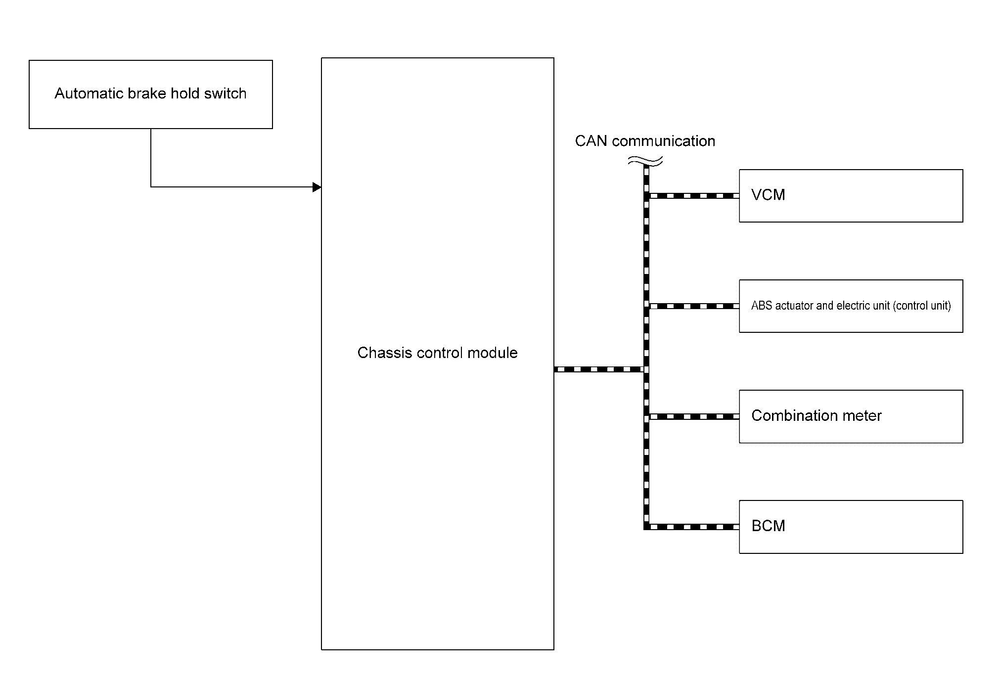
ComponentSignal description
VCM

Mainly transmits the following signals to chassis control module via CAN communication.

  • Accelerator pedal position signal

  • Traction motor torque signal

  • Shift position signal

ABS actuator and electric unit (control unit)

Mainly transmits the following signals to chassis control module via CAN communication.

  • Brake hold status signal

  • Brake fluid pressure signal

  • Front LH wheel speed signal

  • Front RH wheel speed signal

  • Rear LH wheel speed signal

  • Rear RH wheel speed signal

  • VDC malfunction signal

  • Decel G sensor signal

  • Electric parking brake malfunction signal

  • Electric parking brake operation signal (switch)

  • Electric parking brake status signal

Combination meter

Mainly receives the following signals from chassis control module via CAN communication.

  • Automatic brake hold indicator lamp signal

  • Meter display signal

BCM

Mainly transmits the following signals to chassis control module via CAN communication.

  • Brake pedal status signal

  • Seat belt buckle switch (driver side) signal

OPERATION

Automatic Brake Hold Function ON (Operation Permitted)

If automatic brake hold switch is pressed when Automatic brake hold function is OFF, automatic brake hold function turns ON. In addition, automatic brake hold switch indicator illuminates.

Automatic Brake Hold Function OFF (Operation Not Permitted)

If automatic brake hold switch is pressed when automatic brake hold function is ON, automatic brake hold function turns OFF. In addition, automatic brake hold switch indicator turns OFF. [If automatic brake hold indicator lamp (white or green) is ON, it turns OFF.]

Standby

When all of the following conditions are satisfied, automatic brake hold function enters in the standby state, and automatic brake hold indicator lamp (white) illuminates.

  • Seat belt (driver side) is fastened

  • Electric parking brake is released

  • Shift position is not in the P

  • Automatic brake hold switch is ON

Operation

If all of the following conditions are satisfied in the standby state, automatic brake hold function operates, and the color of automatic brake hold indicator lamp changes from white to green. In addition, automatic brake hold display appears.

  • Vehicle speed: 0 km/h

  • Brake pedal is depressed

  • Automatic brake hold function is in the standby state [automatic brake hold switch indicator and automatic brake hold indicator lamp (white) are illuminated]

  • Not on a steep slope

  • Seat belt (driver side) is fastened

  • Electric parking brake is released

  • Shift position is not in the P

Release (Starting Vehicle)

If the following condition is satisfied while automatic brake hold function is being applied, automatic brake hold function is released. (The color of automatic brake hold indicator lamp changes from green to white.)

  • The vehicle is started.

Release (Automatic Brake Hold Switch)

If the following condition is satisfied while automatic brake hold function is being applied, automatic brake hold function is released. (Automatic brake hold indicator lamp turns OFF.)

  • Operate automatic brake hold switch while depressing brake pedal.

Release (Changing to Electric Parking Brake)

If any of the following conditions are met while automatic brake hold function is being applied, electric parking brake is operated automatically, and automatic brake hold function is released. (Automatic brake hold indicator lamp turns OFF.)

  • Operation of Automatic brake hold function is continued for approximately 3 minutes

  • Shift position is in the P

  • The electric parking brake is applied manually

  • Seat belt (driver side) is unfastened

  • Door (driver side) is opened

  • Power switch OFF

  • A malfunction is detected in automatic brake hold function

Parking

  • If shift position is in the P while automatic brake hold function is being applied, automatic brake hold function is released. (Automatic brake hold indicator lamp turns OFF.)

  • If electric parking brake is applied while automatic brake hold function is being applied, automatic brake hold function is released. (Automatic brake hold indicator lamp turns OFF.)

Timing Chart

  • The vehicle is started while automatic brake hold function is being applied
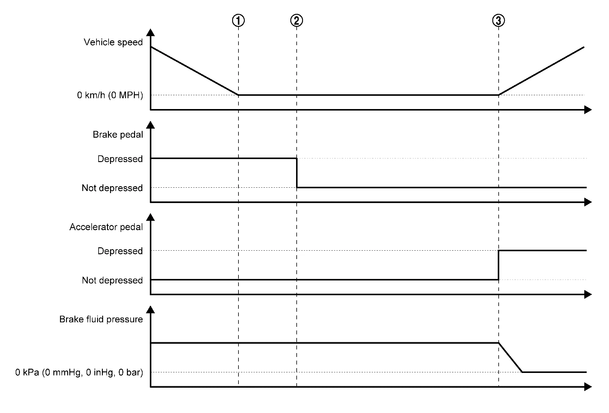
    When the Nissan Ariya vehicle is stopped by a brake operation by the driver, maintaining of brake fluid pressure is started.
    Automatic brake hold function is applied (this function holds brake fluid pressure even after the driver has released brake pedal).
    When the driver performs starting operation, automatic brake hold function is released (brake fluid pressure is decreased).
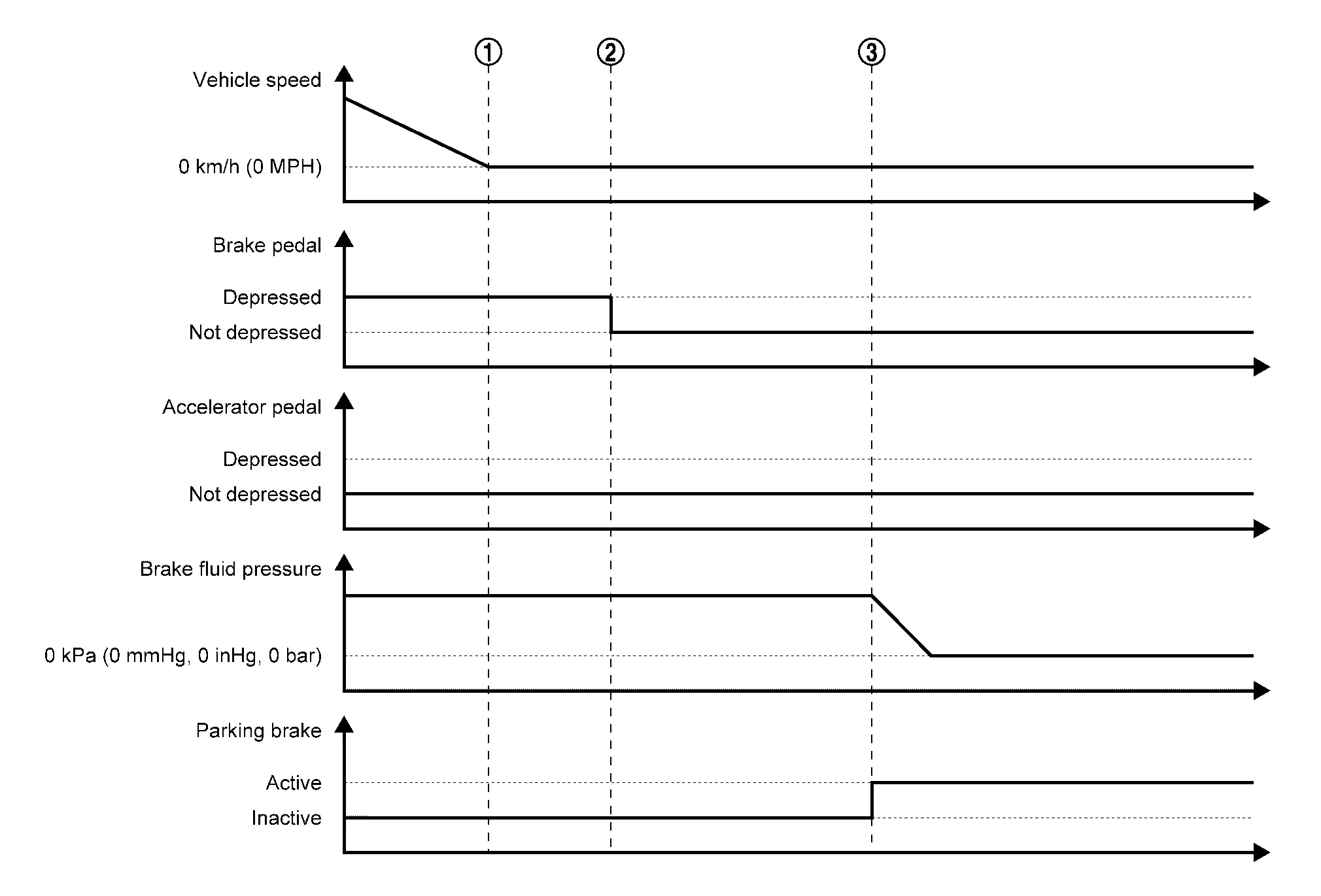
  • Changing the Nissan Ariya vehicle holding method to electric parking brake while automatic brake hold function is being applied

    When the Nissan Ariya vehicle is stopped by a brake operation by the driver, maintaining of the brake fluid pressure is started.
    Automatic brake hold function is applied (this function holds brake fluid pressure even after the driver has released brake pedal).
    If the conditions for changing to electric parking brake are satisfied while automatic brake hold function is being applied, the method of holding the Nissan Ariya vehicle stopped is automatically changed to electric parking brake.

Circuit Diagram

Refer to Circuit Diagram.

Fail-safe

Refer to Fail-safe.

Warning / Indicator / Chime List

NameDesignLayout/Function
Automatic brake hold indicator lamp For layout: Refer to Design.
For function: Refer to Automatic Brake Hold Indicator Lamp.

Chassis Control Warning (automatic Brake Hold) Nissan Ariya

System Description

DESIGN/PURPOSE

Notifies the driver when the vehicle is moved or may start moving while automatic brake hold function is being applied.

DesignWarning messageDescription
—

Press brake

pedal to

prevent rolling
When the Nissan Ariya vehicle moves or possibly moves while automatic brake hold function activates.

Caution Steep

slope
When the automatic brake hold function activates on the steep slope.

Steep Slope

Apply foot

brake
When the brake pedal is not depressed while the automatic brake hold function activates on the steep slope for 3 minutes approximately.

Press brake to

operate switch
  • When the automatic brake hold switch is pushed without depressing brake pedal while the automatic brake hold function activates.

  • When Automatic brake hold function cannot be released even if the accelerator pedal is depressed on steep slope.

SYNCHRONIZATION WITH WARNING CHIME

Warning message—

Press brake

pedal to

prevent rolling
Applicable

Caution Steep

slope
NO

Steep Slope

Apply foot

brake
NO

Press brake to

operate switch
NO

SYNCHRONIZATION WITH MASTER WARNING LAMP

Warning message—

Press brake

pedal to

prevent rolling
Applicable

Caution Steep

slope
NO

Steep Slope

Apply foot

brake
NO

Press brake to

operate switch
NO

Refer to Master Warning Lamp.

SYSTEM DIAGRAM
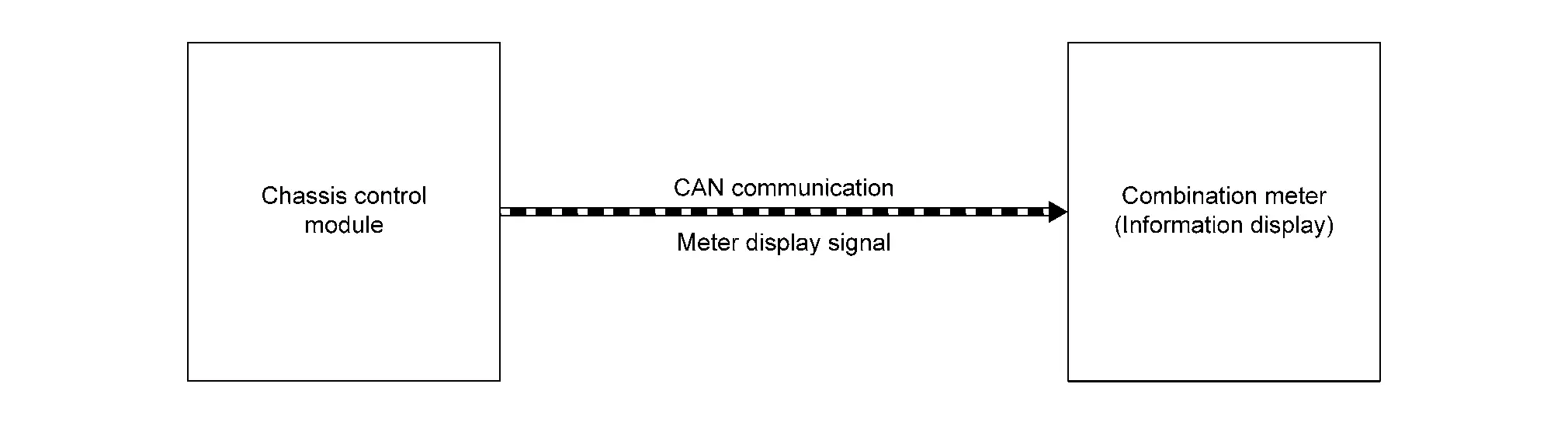
When all of the following conditions are satisfied.

  • Automatic brake hold function applied

  • Vehicle is moved; vehicle may start moving; or a malfunction is detected in automatic brake hold function (chassis control module). Refer to DTC Index.