System Description

System

In this manual: System Description
How to Use This Manual — 1Precautions — 1Preparation — 1Vehicle Information — 1Basic Inspection — 1Preparation. Commercial Service Tools Or/and Repair Part — 1Description — 1Component Parts — 1System — 1Diagnosis System (vcm) — 1Ecu Diagnosis Information. Vcm — 1Ev Control System — 1Ev/hev (vcm) — 1Component Parts /circuit Diagnosis — 1Ev Control System — 1Periodic Maintenance. Ev System Warning Lamp — 1Removal and Installation. Vcm — 1Traction Motor System :: Front Traction Motor — 1Preparation — 1Description — 4Basic Inspection — 2Dtc Diagnosis — 2Component Parts /circuit Diagnosis — 1Traction Motor System :: Rear Traction Motor — 1Description — 4Basic Inspection — 2Dtc Diagnosis — 2Component Parts /circuit Diagnosis — 1Removal and Installation — 1Ev Battery System :: 66kwh Li-Ion Battery — 1Description — 4Basic Inspection — 2Dtc Diagnosis — 2Component Parts /circuit Diagnosis — 1Removal and Installation — 1Disassembly and Assembly — 2Service Data — 1Ev Battery System :: 91kwh Li-Ion Battery — 1Description — 4Basic Inspection — 2Dtc Diagnosis — 2Component Parts /circuit Diagnosis — 1Removal and Installation — 1Disassembly and Assembly — 1Service Data — 2Preparation. Vehicle Charging System — 1Vehicle Charging System :: Description — 1Component Parts — 2System — 1Diagnosis System (on-Board Charger) — 1Diagnosis System (dc/dc Converter) — 1Ecu Diagnosis Information — 1Vehicle Charging System — 1Charger/pd Module (on-Board Charger) — 1Cplc (cplc) — 1Dcdc (dc/dc Converter) — 1Component Parts/circuit Diagnosis — 1Symptom Diagnosis — 1Evse Inspection — 1Periodic Maintenance — 1Removal and Installation — 1Disassembly and Assembly — 1Preparation. High Voltage Cooling System — 1Description — 1Symptom Diagnosis. Overheating Cause Analysis — 1Periodic Maintenance — 1Coolant — 1Removal and Installation — 1Radiator — 1Service Data — 1Removal and Installation. Accelerator Control System — 1Reduction Gear: Re1f62a — 1Removal and Installation — 1Transaxle & Transmission :: Electric Shift — 1Description — 3Basic Inspection — 2Dtc Diagnosis — 2Component Parts /circuit Diagnosis — 1Removal and Installation — 1Rear Final Drive: Rn1r62a — 1Removal and Installation — 1Preparation. Front Axle System — 1Symptom Diagnosis. Noise, Vibration and Harshness (nvh) Troubleshooting — 1Periodic Maintenance — 1Removal and Installation — 1Service Data. Front Drive Shaft — 12wd — 14wd — 1Periodic Maintenance — 1Removal and Installation — 1Preparation. Front Suspension System — 1Symptom Diagnosis. Noise, Vibration and Harshness (nvh) Troubleshooting — 1Periodic Maintenance — 1Removal and Installation — 1Service Data — 1Symptom Diagnosis. Noise, Vibration and Harshness (nvh) Troubleshooting — 1Periodic Maintenance — 1Removal and Installation — 1Service Data — 1Preparation. Road Wheels & Tires System — 1Description — 1System — 1Ecu Diagnosis Information. Bcm (body Control Module) — 1Tpms — 1Dtc/circuit Diagnosis — 1Symptom Diagnosis — 1Periodic Maintenance. Road Wheels & Tires — 1Removal and Installation — 1Service Data — 1Preparation. Brake System — 1System Description — 1Component Parts — 1Ecu Diagnosis Information. Electrically-Driven Intelligent Brake Unit — 1Basic Inspection — 1Dtc/circuit Diagnosis — 1Symptom Diagnosis — 1Periodic Maintenance — 1Removal and Installation — 1Service Data — 1Preparation. Parking Brake System — 1System Description — 1Component Parts — 1System — 1Ecu Diagnosis Information. Abs Actuator and Electric Unit (control Unit) — 1Basic Inspection. Diagnosis and Repair Work Flow — 1Component Parts /circuit Diagnosis — 1Symptom Diagnosis — 1Removal and Installation — 1Brake Control System :: With Vdc — 1System Description — 3Basic Inspection — 2Dtc/circuit Diagnosis — 1Symptom Diagnosis — 2Removal and Installation — 1Brake Control System :: Automatic Brake Hold — 1System Description — 3Component Parts /circuit Diagnosis — 1Removal and Installation — 1Brake Control System :: E-Step — 1System Description — 3Removal and Installation — 1System Description — 1Ecu Diagnosis Information — 1Basic Inspection — 1Symptom Diagnosis — 1Rear Automatic Braking — 1System Description — 1Basic Inspection — 1Preparation. Steering System — 1System Description — 1Component Parts — 1Basic Inspection — 1Dtc/circuit Diagnosis — 1Symptom Diagnosis — 1Periodic Maintenance. Steering Wheel — 1Removal and Installation — 1Service Data — 1System Description — 1Component Parts — 1Steering Control System — 1Ecu Diagnosis Information. Power Steering Control Module — 1Dtc/circuit Diagnosis — 1Component Parts /circuit Diagnosis — 1Symptom Diagnosis — 1Removal and Installation. Power Steering Control Module — 1System Description — 1Removal and Installation — 1System Description — 1System — 1Basic Inspection. Diagnosis and Repair Work Flow — 1Dtc/circuit Diagnosis — 1Symptom Diagnosis — 1Component Parts — 1Basic Inspection — 1Removal and Installation — 1System Description — 1System — 1Ecu Diagnosis Information. Air Bag Diagnosis Sensor Unit — 1Basic Inspection — 1Dtc/circuit Diagnosis — 1Symptom Diagnosis — 1System Description. Description. Ventilation System — 1Removal and Installation — 1Preparation. Preparation — 1System Description — 1Basic Inspection — 1Symptom Diagnosis — 1Removal and Installation — 1Electric Compressor — 1Cooler Pipe and Hose — 1A/c Unit Assembly Cover — 1A/c Unit Assembly — 1Heater & Air Conditioning Control System :: Automatic Air Conditioning — 1System Description — 1Ecu Diagnosis Information — 1Basic Inspection — 2Dtc Diagnosis — 1Symptom Diagnosis — 1Removal and Installation — 2Preparation. Preparation — 1Symptom Diagnosis. Squeak and Rattle Trouble Diagnoses — 1Removal and Installation — 1Preparation. Instrument Panel — 1Component Parts — 1System — 1Ecu Diagnosis Information. Flexible Center Storage Control Module — 1Basic Inspection. Diagnosis and Repair Work Flow — 1Dtc/circuit Diagnosis — 1Symptom Diagnosis — 1Removal and Installation — 1Preparation. Preparation — 1Component Parts — 1System — 1Ecu Diagnosis Information. Driver Lumbar Support Control Module — 1Basic Inspection. Diagnosis and Repair Work Flow — 1Dtc/circuit Diagnosis — 1Symptom Diagnosis — 1Removal and Installation — 1System Description — 1System — 1Ecu Diagnosis Information — 1Basic Inspection — 1Dtc/circuit Diagnosis — 1Symptom Diagnosis — 1Manual Function Does Not Operate — 1Memory Function Does Not Operate — 1Removal and Installation — 1Preparation. Preparation — 1System Description — 1System (intelligent Key System) — 1Diagnosis System (bcm) — 1Ecu Diagnosis Information — 1Basic Inspection — 1Dtc/circuit Diagnosis — 1U2141-87 Can Comm Circuit — 1Power Supply and Ground Circuit — 1Symptom Diagnosis — 1Automatic Back Door Operation Does Not Operate — 1Back Door Does Not Open — 1Door Does Not Lock/unlock with Door Lock and Unlock Switch — 1Removal and Installation — 1Hood — 1Radiator Core Support — 1Charge Port Lid — 1Front Fender — 1Front Door — 1Rear Door — 1Back Door — 1Hood Lock — 1Front Door Lock — 1Rear Door Lock — 1Back Door Lock — 1Outside Key Antenna — 1System Description — 1System — 1Ecu Diagnosis Information. Inverter (front), Inverter (rear), Bcm, Intelligent Key Unit — 1Basic Inspection — 1Dtc/circuit Diagnosis — 1Symptom Diagnosis — 1Preparation — 1Symptom Diagnosis. Squeak and Rattle Trouble Diagnoses — 1Removal and Installation — 1System Description — 1Ecu Diagnosis Information — 1Basic Inspection — 1Dtc/circuit Diagnosis — 1Power Supply and Ground Circuit — 1Symptom Diagnosis — 1Front Passenger Side Power Window Does Not Operate — 1Rear Lh Side Power Window Does Not Operate — 1Rear Rh Side Power Window Does Not Operate — 1Removal and Installation. Power Window Main Switch — 1Preparation. Preparation — 1System Description — 1Ecu Diagnosis Information — 1Basic Inspection — 1Dtc/circuit Diagnosis — 1Power Supply and Ground Circuit — 1Sunroof Switch Assembly — 1Symptom Diagnosis — 1Auto Operation Does Not Operate — 1Removal and Installation — 1Preparation — 1Description — 1Symptom Diagnosis. Squeak and Rattle Trouble Diagnoses — 1Removal and Installation — 1Service Information — 6Repair Information — 1Precaution — 1Preparation — 1Removal and Installation — 1Service Data — 1Preparation. Preparation — 1Component Parts — 1System — 1Ecu Diagnosis Information — 1Wiring Diagram. Door Mirror — 1Basic Inspection. Diagnosis and Repair Work Flow — 1Dtc/circuit Diagnosis — 1Power Supply and Ground Circuit — 1Symptom Diagnosis — 1Removal and Installation — 1Exterior Lighting System :: Led Headlamp — 1System Description — 3Basic Inspection — 1Dtc/circuit Diagnosis — 1Symptom Diagnosis — 1Periodic Maintenance — 1Removal and Installation — 1System Description — 1System — 1Diagnosis System (bcm) — 1Ecu Diagnosis Information. Bcm, Intelligent Key Unit — 1Basic Inspection. Diagnosis and Repair Work Flow — 1Dtc/circuit Diagnosis — 1Symptom Diagnosis. Interior Lighting System Symptom — 1Removal and Installation — 1Service Data. Bulb Specifications — 1System Description — 1System — 1Ecu Diagnosis Information. Bcm, Ipdm E/r — 1Basic Inspection. Diagnosis and Repair Work Flow — 1Dtc/circuit Diagnosis — 1Symptom Diagnosis — 1Removal and Installation — 1System Description — 1Ecu Diagnosis Information. Bcm — 1Basic Inspection. Diagnosis and Repair Work Flow — 1Dtc/circuit Diagnosis — 1Symptom Diagnosis — 1Removal and Installation — 1Preparation. Preparation — 1Removal and Installation. Horn — 1Preparation. Commercial Service Tools Or/and Repair Part — 1System Description — 1Component Parts — 1Ecu Diagnosis Information. Approaching Vehicle Sound for Pedestrians (vsp) Control Unit — 1Approaching Vehicle Sound for Pedestrians (vsp) — 1Vsp [approaching Vehicle Sound for Pedestrians (vsp) Control Unit] — 1Approaching Vehicle Sound for Pedestrians (vsp) System — 1Removal and Installation — 1Removal and Installation — 1Wireless Charger — 1System Description — 1Basic Inspection — 1Dtc/circuit Diagnosis — 1Removal and Installation — 1Component Parts — 1System — 1Diagnosis System (bcm) — 1Ecu Diagnosis Information. Bcm — 1Basic Inspection — 1Dtc/circuit Diagnosis — 1Symptom Diagnosis — 1Removal and Installation — 1Can Fundamental — 1Description — 1Trouble Diagnosis — 1Can (controller Area Network) — 1Description — 1
~7min read
  • E-Step
  • E-Step Display
  • E-Step Warning

E-Step Nissan Ariya 1st generation

System Description

  • The e-Step function enables the driver to slow the vehicle, by operating only the accelerator pedal.
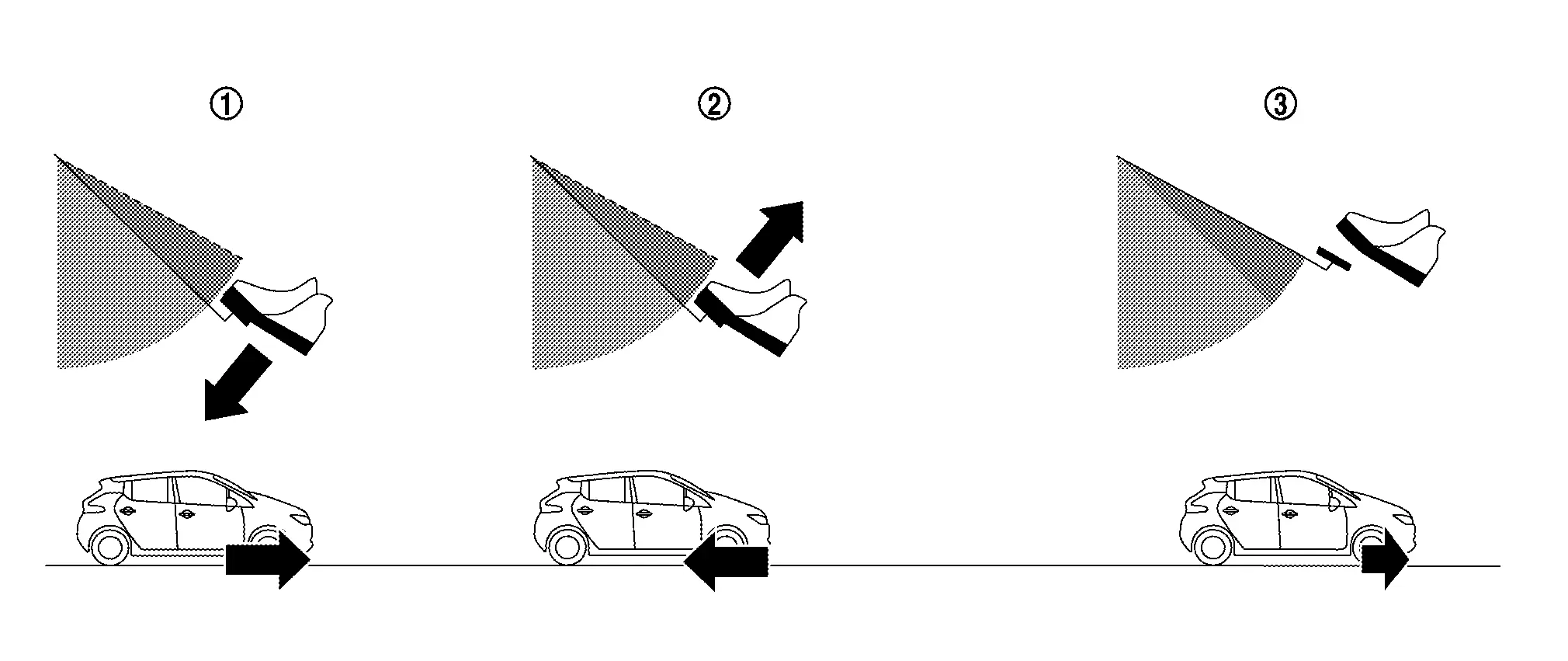
    Acceleration
    Deceleration
    Extremely low speed (creep)
  • When the e-Step function is ON, the regenerative brake is enhanced and the driver can adjust the Nissan Ariya vehicle speed by only depressing or returning the accelerator pedal.

  • e-Step function is controlled by receiving input signal from chassis control module, VCM and electrically-driven intelligent brake unit via CAN communication and each related switches.

SYSTEM DIAGRAM
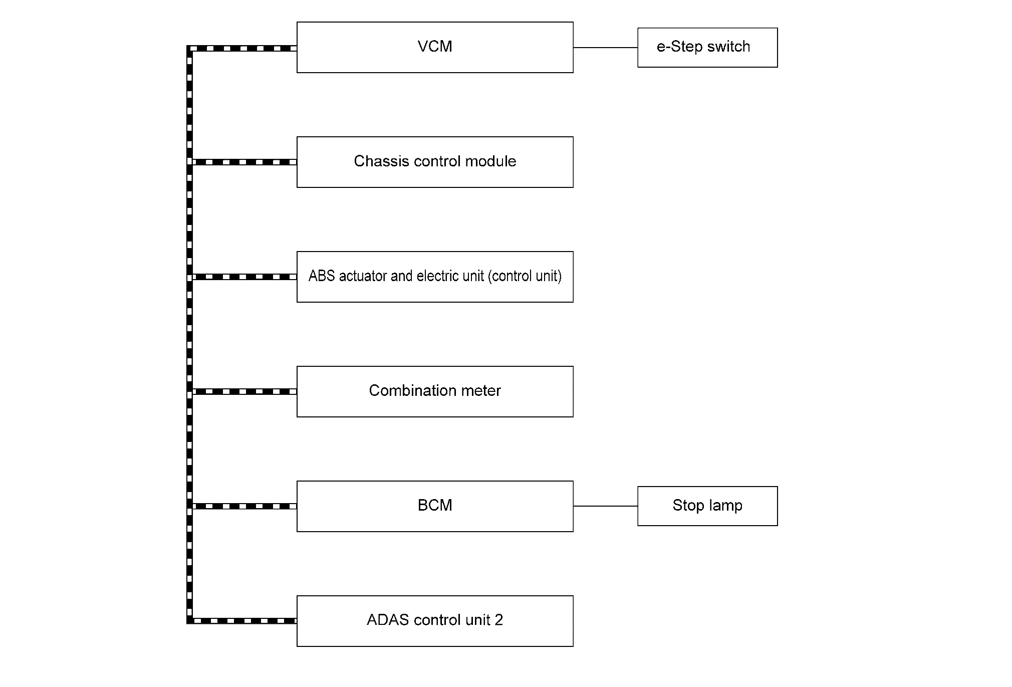
ComponentSignal description
VCM

Mainly transmits the following signals to chassis control module via CAN communication.

  • Request drive torque signal

  • e-Step status signal

  • VCM malfunction signal

  • Shift position signal

  • Motor speed signal

  • Estimate slop signal

  • Accelerator pedal position signal

  • Estimate drive torque signal

  • Coast deceleration torque signal

  • Traction motor torque signal

Mainly receives the following signals from ABS actuator and electric unit (control unit) via CAN communication.

  • Brake torque signal

Mainly receives the following signals from chassis control module via CAN communication.

  • Chassis control module malfunction signal

  • Slop estimate permission signal

  • Coast limit torque signal

Mainly receives the following signals from ADAS control unit 2 via CAN communication.

  • Intelligent cruise control signal

  • ProPILOT status signal

ABS actuator and electric unit (control unit)

Mainly transmits the following signals to chassis control module via CAN communication.

  • ABS operation signal

  • ABS malfunction signal

  • VDC operation signal

  • VDC malfunction signal

  • Steering angle sensor signal

  • Front LH wheel speed signal

  • Front RH wheel speed signal

  • Rear LH wheel speed signal

  • Rear RH wheel speed signal

  • Deceleration control permission status signal

  • Target brake force signal

Mainly receives the following signals from chassis control module via CAN communication.

  • Stop lamp ON request signal

Mainly transmits the following signals to VCM via CAN communication.

  • Electric parking brake operation status signal

  • Regenerative request torque signal

Mainly receives the following signals from VCM via CAN communication.

  • Coast deceleration torque signal

  • Accelerator pedal position signal

  • Motor speed signal

  • Shift position signal

  • Estimate drive torque signal

  • Regenerative possible torque signal

Combination meter

Mainly transmits the following signals to VCM via CAN communication.

  • e-Step mode memory setting signal

Mainly receives the following signals from VCM via CAN communication.

  • e-Step mode display signal

  • e-Step malfunction display signal

  • e-Step memory status signal

Mainly receives the following signals from BCM via CAN communication.

  • Stop lamp ON status signal

Mainly receives the following signals from chassis control module via CAN communication.

  • Meter display signal

BCM

Mainly transmits the following signals to chassis control module via CAN communication.

  • Stop lamp switch malfunction signal

Mainly receives the following signals from ABS actuator and electric unit (control unit) via CAN communication.

  • Stop lamp request signal

ADAS control unit 2

Mainly transmits the following signals to chassis control module and VCM via CAN communication.

  • ProPILOT status signal

Chassis control module

OPERATION OUTLINE

e-Step function ON/OFF

When the power switch is ON, operating the e-Step switch switches the display of the information display of the combination meter.

OPERATION

  • Operation condition

    e-Step function will not be activated in the followings conditions.

    • When shift position is N or P.

    • When any driver assistance systems are activated.

  • Acceleration and deceleration while driving

    • The e-Step function enables the driver to accelerate and decelerate the Nissan Ariya vehicle by operating only the accelerator pedal.

    • When the accelerator pedal is released, the Nissan Ariya vehicle decelerates with a stronger deceleration when the e-Step function is ON than when it is OFF.

    • When the Nissan Ariya vehicle speed decreases, the deceleration decreases, and at extremely low speed, it becomes a creep state as in the e-Step function OFF state.

  • Reverse

As same characteristics as e-Step function OFF.

TIMING CHART

  • When regenerative brake operate (regenerative brake force: sufficient)
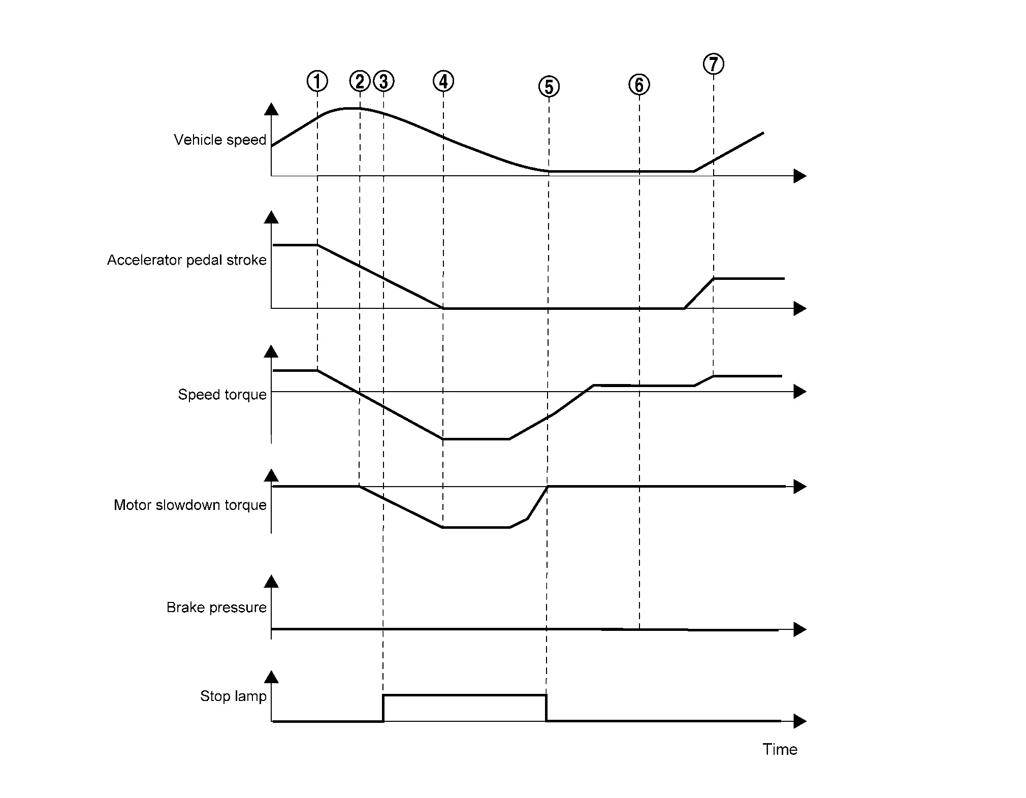
    Returning accelerator pedal
    Timing of acceleration and deceleration (deceleration start).
    Stop lamp turned ON (exceed deceleration speed to turn ON stop lamp)
    Release accelerator pedal
    Stop lamp turned OFF
    Creep state
    Re-acceleration
  • When regenerative brake operate (regenerative brake force: sufficient) / Driver brake
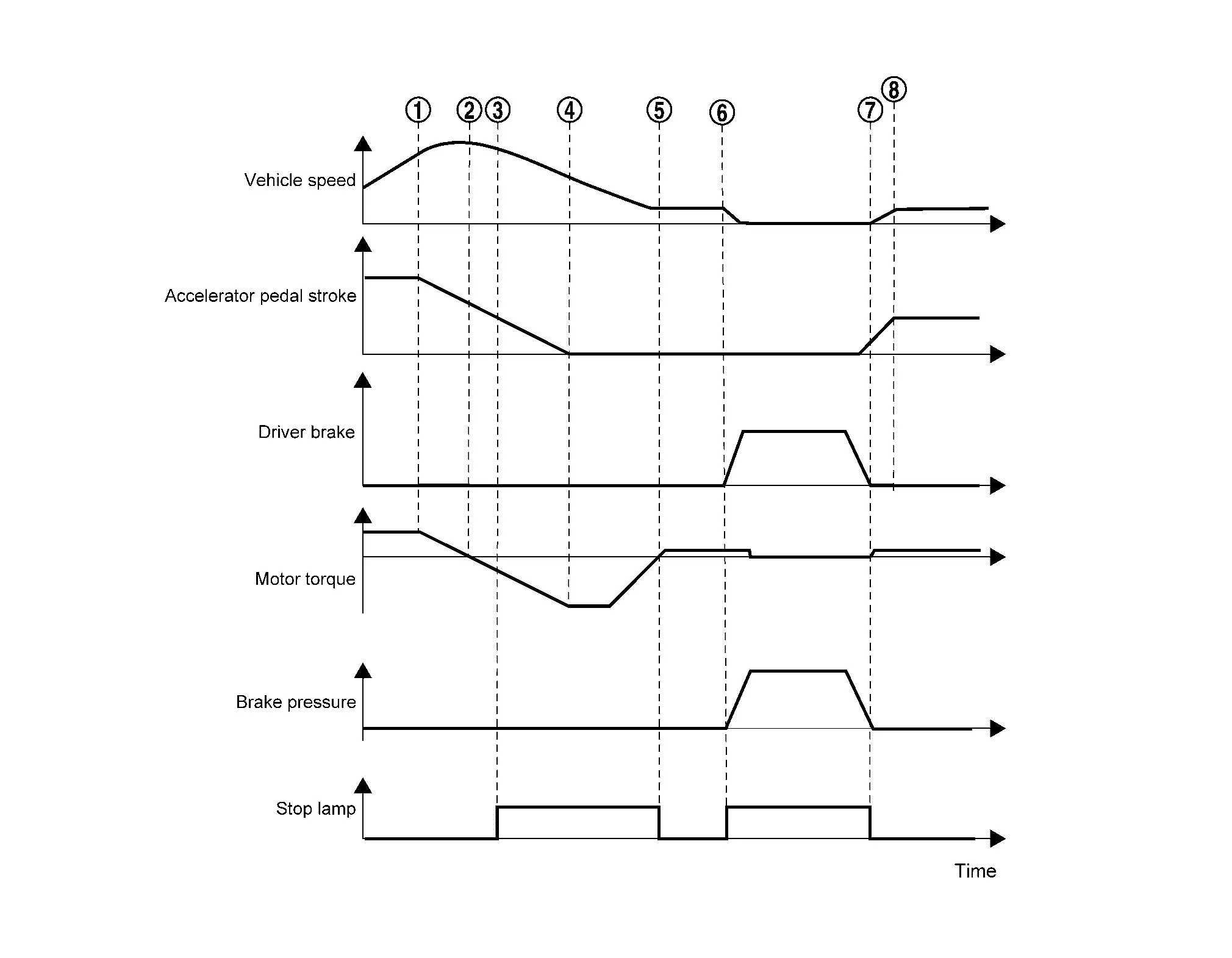
    Returning accelerator pedal
    Timing of acceleration and deceleration (deceleration start).
    Stop lamp turned ON (exceed deceleration speed to turn ON stop lamp)
    Release accelerator pedal
    Creep state / Stop lamp turned OFF
    Depress brake pedal / Stop lamp turned ON
    Release brake pedal / Stop lamp turned OFF
    Re-acceleration
  • When regenerative brake operate (regenerative brake force: insufficient)
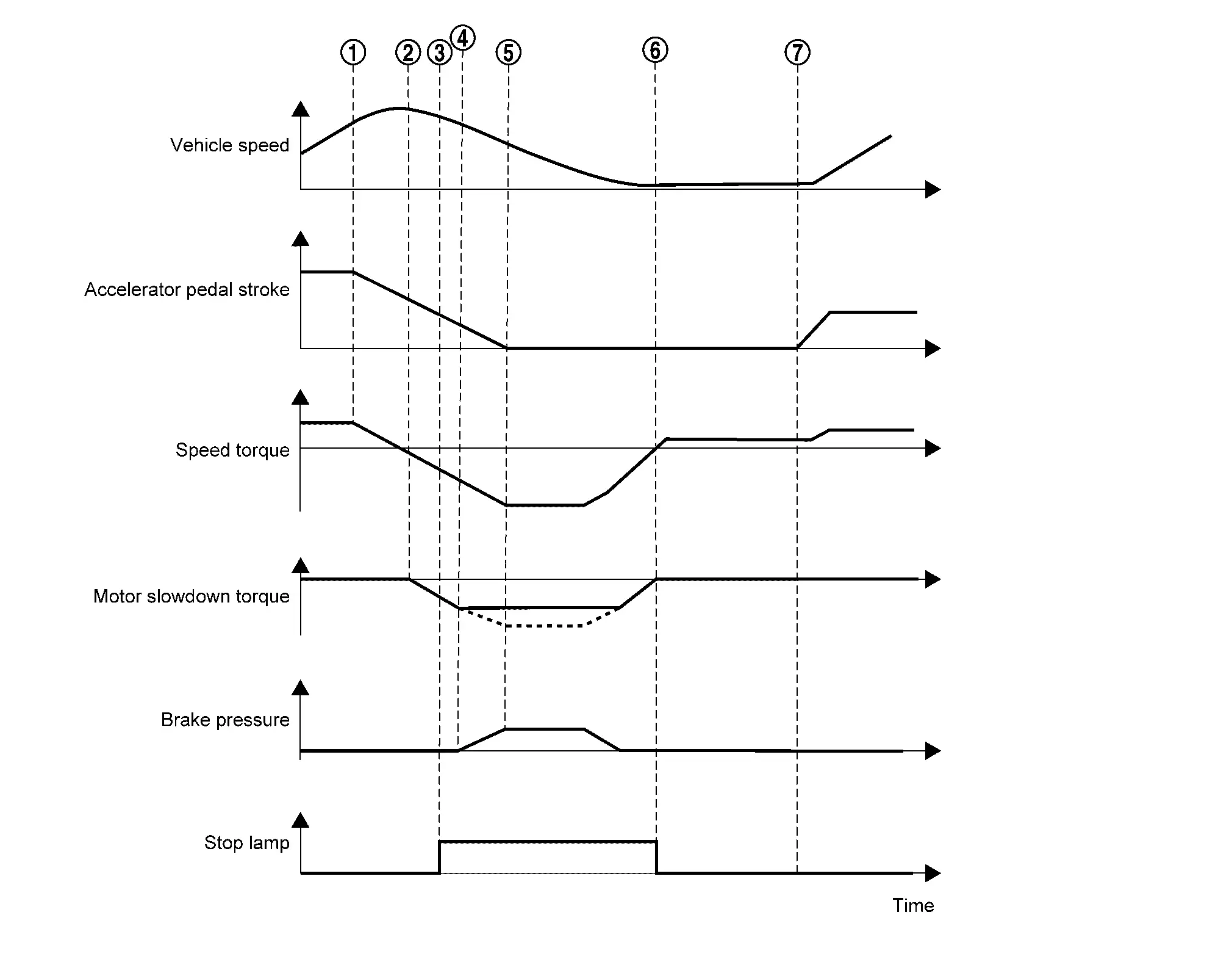
    Returning accelerator pedal
    Timing of acceleration and deceleration (deceleration start)
    Stop lamp turned ON (exceed deceleration speed to turn ON stop lamp)
    Friction (normal) brake assists deceleration because regenerative braking amount is insufficient
    Release accelerator pedal (maximum deceleration)
    Creep state / Stop lamp turned OFF
    Re-acceleration
  • When regenerative brake does not operate
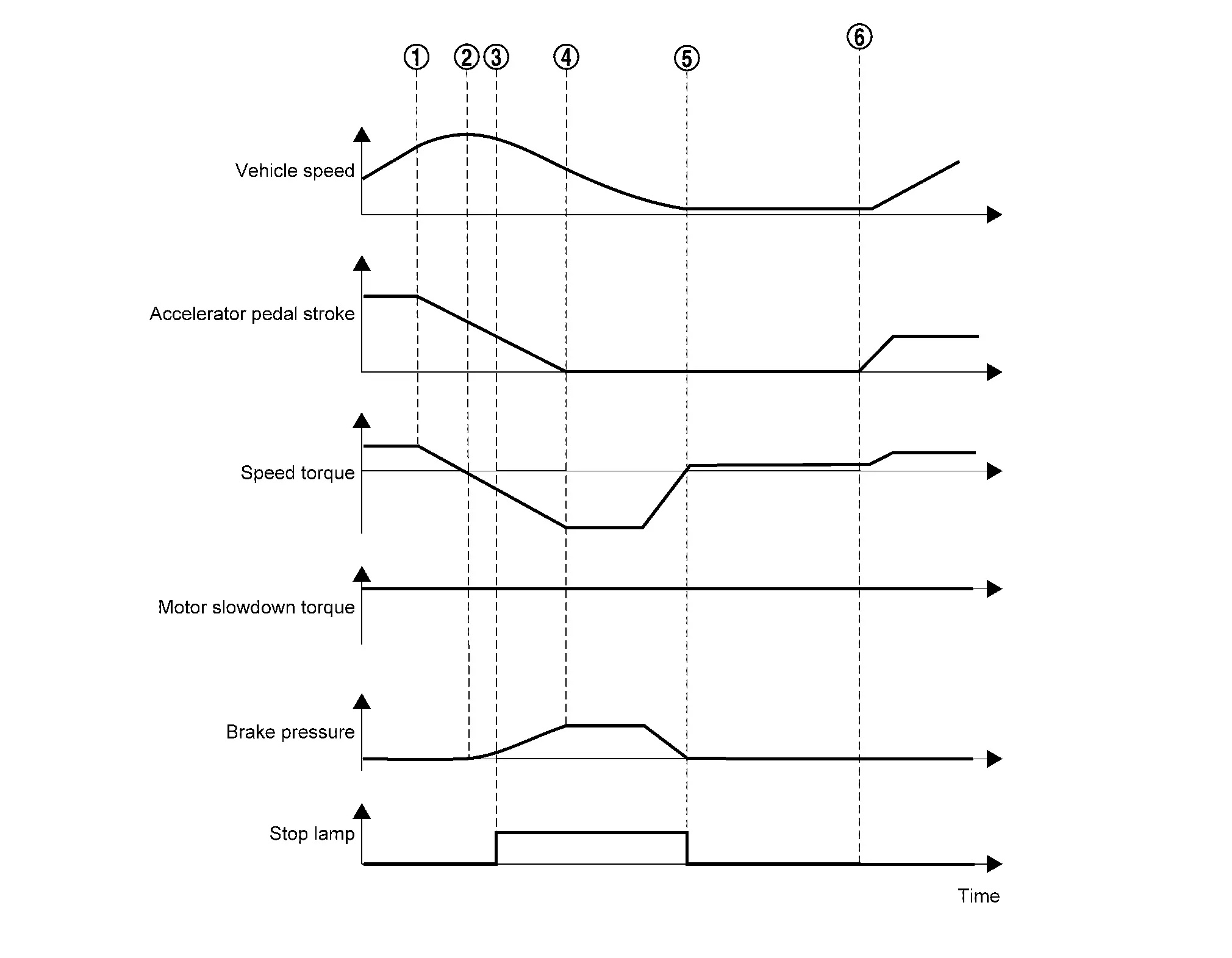
    Returning accelerator pedal
    Timing of acceleration and deceleration (deceleration start)
    Stop lamp turned ON (exceed deceleration speed to turn ON stop lamp)
    Release accelerator pedal (maximum deceleration)
    Creep state / Stop lamp turned OFF
    Nissan Ariya Vehicle restart

RETAIN MODE

  • Allows driver to maintain the e-Step function setting ''ON'' or ''OFF''.
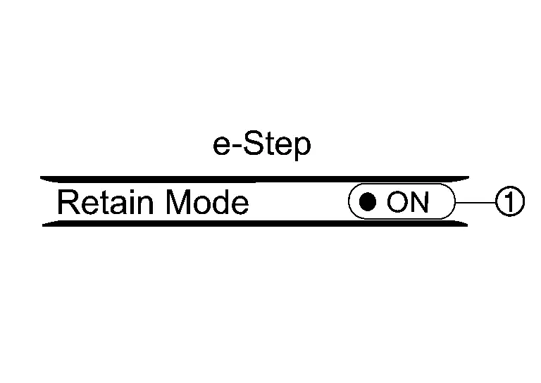
  • When mode memory turned ON, previous e-Step function setting (ON/OFF) will be kept.

  • The mode is switched on the Nissan Ariya vehicle information display of the combination meter.

Circuit Diagram

Refer to Circuit Diagram.

Fail-safe

Refer to Fail-safe.

Operation

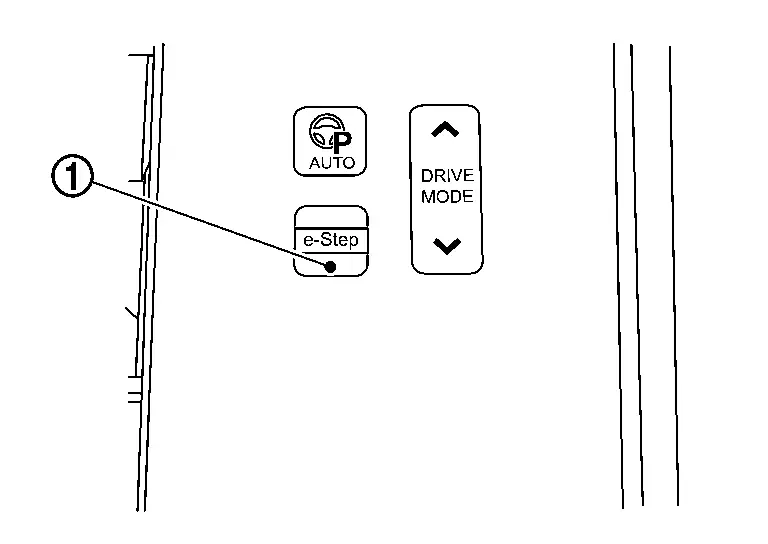
The e-Step function turns ON or OFF each time the e-Step switch is pushed. The e-Step indicator in the information display shows the status of the e-Step function.
E-Step Display Nissan Ariya 1st generation

System Description

DESIGN/PURPOSE

Indicator informs the status of e-Step function.

DISPLAY

DesignDescription
The e-Step function turned ON
The e-Step function turned OFF

SYNCHRONIZATION WITH MASTER WARNING LAMP

Not applicable

SYSTEM DIAGRAM

LIGHTING CONDITION

Regarding e-Step function turned ON/OFF, Refer to System Description.

E-Step Warning Nissan Ariya: FE0

System Description

DESIGN/PURPOSE

Inform the driver when e-Step function is malfunctioning.

  • e-Step system failure Press brake pedal to slow or stop

SYNCHRONIZATION WITH WARNING CHIME

Not applicable

SYNCHRONIZATION WITH MASTER WARNING LAMP

Applicable

Refer to Master Warning Lamp.

SYSTEM DIAGRAM

When e-Step function is malfunctioning