Description

System

In this manual: Description
How to Use This Manual — 1Precautions — 1Preparation — 1Vehicle Information — 1Basic Inspection — 1Preparation. Commercial Service Tools Or/and Repair Part — 1Description — 1Component Parts — 1System — 1Diagnosis System (vcm) — 1Ecu Diagnosis Information. Vcm — 1Ev Control System — 1Ev/hev (vcm) — 1Component Parts /circuit Diagnosis — 1Ev Control System — 1Periodic Maintenance. Ev System Warning Lamp — 1Removal and Installation. Vcm — 1Traction Motor System :: Front Traction Motor — 1Preparation — 1Description — 4Basic Inspection — 2Dtc Diagnosis — 2Component Parts /circuit Diagnosis — 1Traction Motor System :: Rear Traction Motor — 1Description — 4Basic Inspection — 2Dtc Diagnosis — 2Component Parts /circuit Diagnosis — 1Removal and Installation — 1Ev Battery System :: 66kwh Li-Ion Battery — 1Description — 4Basic Inspection — 2Dtc Diagnosis — 2Component Parts /circuit Diagnosis — 1Removal and Installation — 1Disassembly and Assembly — 2Service Data — 1Ev Battery System :: 91kwh Li-Ion Battery — 1Description — 4Basic Inspection — 2Dtc Diagnosis — 2Component Parts /circuit Diagnosis — 1Removal and Installation — 1Disassembly and Assembly — 1Service Data — 2Preparation. Vehicle Charging System — 1Vehicle Charging System :: Description — 1Component Parts — 2System — 1Diagnosis System (on-Board Charger) — 1Diagnosis System (dc/dc Converter) — 1Ecu Diagnosis Information — 1Vehicle Charging System — 1Charger/pd Module (on-Board Charger) — 1Cplc (cplc) — 1Dcdc (dc/dc Converter) — 1Component Parts/circuit Diagnosis — 1Symptom Diagnosis — 1Evse Inspection — 1Periodic Maintenance — 1Removal and Installation — 1Disassembly and Assembly — 1Preparation. High Voltage Cooling System — 1Description — 1Symptom Diagnosis. Overheating Cause Analysis — 1Periodic Maintenance — 1Coolant — 1Removal and Installation — 1Radiator — 1Service Data — 1Removal and Installation. Accelerator Control System — 1Reduction Gear: Re1f62a — 1Removal and Installation — 1Transaxle & Transmission :: Electric Shift — 1Description — 3Basic Inspection — 2Dtc Diagnosis — 2Component Parts /circuit Diagnosis — 1Removal and Installation — 1Rear Final Drive: Rn1r62a — 1Removal and Installation — 1Preparation. Front Axle System — 1Symptom Diagnosis. Noise, Vibration and Harshness (nvh) Troubleshooting — 1Periodic Maintenance — 1Removal and Installation — 1Service Data. Front Drive Shaft — 12wd — 14wd — 1Periodic Maintenance — 1Removal and Installation — 1Preparation. Front Suspension System — 1Symptom Diagnosis. Noise, Vibration and Harshness (nvh) Troubleshooting — 1Periodic Maintenance — 1Removal and Installation — 1Service Data — 1Symptom Diagnosis. Noise, Vibration and Harshness (nvh) Troubleshooting — 1Periodic Maintenance — 1Removal and Installation — 1Service Data — 1Preparation. Road Wheels & Tires System — 1Description — 1System — 1Ecu Diagnosis Information. Bcm (body Control Module) — 1Tpms — 1Dtc/circuit Diagnosis — 1Symptom Diagnosis — 1Periodic Maintenance. Road Wheels & Tires — 1Removal and Installation — 1Service Data — 1Preparation. Brake System — 1System Description — 1Component Parts — 1Ecu Diagnosis Information. Electrically-Driven Intelligent Brake Unit — 1Basic Inspection — 1Dtc/circuit Diagnosis — 1Symptom Diagnosis — 1Periodic Maintenance — 1Removal and Installation — 1Service Data — 1Preparation. Parking Brake System — 1System Description — 1Component Parts — 1System — 1Ecu Diagnosis Information. Abs Actuator and Electric Unit (control Unit) — 1Basic Inspection. Diagnosis and Repair Work Flow — 1Component Parts /circuit Diagnosis — 1Symptom Diagnosis — 1Removal and Installation — 1Brake Control System :: With Vdc — 1System Description — 3Basic Inspection — 2Dtc/circuit Diagnosis — 1Symptom Diagnosis — 2Removal and Installation — 1Brake Control System :: Automatic Brake Hold — 1System Description — 3Component Parts /circuit Diagnosis — 1Removal and Installation — 1Brake Control System :: E-Step — 1System Description — 3Removal and Installation — 1System Description — 1Ecu Diagnosis Information — 1Basic Inspection — 1Symptom Diagnosis — 1Rear Automatic Braking — 1System Description — 1Basic Inspection — 1Preparation. Steering System — 1System Description — 1Component Parts — 1Basic Inspection — 1Dtc/circuit Diagnosis — 1Symptom Diagnosis — 1Periodic Maintenance. Steering Wheel — 1Removal and Installation — 1Service Data — 1System Description — 1Component Parts — 1Steering Control System — 1Ecu Diagnosis Information. Power Steering Control Module — 1Dtc/circuit Diagnosis — 1Component Parts /circuit Diagnosis — 1Symptom Diagnosis — 1Removal and Installation. Power Steering Control Module — 1System Description — 1Removal and Installation — 1System Description — 1System — 1Basic Inspection. Diagnosis and Repair Work Flow — 1Dtc/circuit Diagnosis — 1Symptom Diagnosis — 1Component Parts — 1Basic Inspection — 1Removal and Installation — 1System Description — 1System — 1Ecu Diagnosis Information. Air Bag Diagnosis Sensor Unit — 1Basic Inspection — 1Dtc/circuit Diagnosis — 1Symptom Diagnosis — 1System Description. Description. Ventilation System — 1Removal and Installation — 1Preparation. Preparation — 1System Description — 1Basic Inspection — 1Symptom Diagnosis — 1Removal and Installation — 1Electric Compressor — 1Cooler Pipe and Hose — 1A/c Unit Assembly Cover — 1A/c Unit Assembly — 1Heater & Air Conditioning Control System :: Automatic Air Conditioning — 1System Description — 1Ecu Diagnosis Information — 1Basic Inspection — 2Dtc Diagnosis — 1Symptom Diagnosis — 1Removal and Installation — 2Preparation. Preparation — 1Symptom Diagnosis. Squeak and Rattle Trouble Diagnoses — 1Removal and Installation — 1Preparation. Instrument Panel — 1Component Parts — 1System — 1Ecu Diagnosis Information. Flexible Center Storage Control Module — 1Basic Inspection. Diagnosis and Repair Work Flow — 1Dtc/circuit Diagnosis — 1Symptom Diagnosis — 1Removal and Installation — 1Preparation. Preparation — 1Component Parts — 1System — 1Ecu Diagnosis Information. Driver Lumbar Support Control Module — 1Basic Inspection. Diagnosis and Repair Work Flow — 1Dtc/circuit Diagnosis — 1Symptom Diagnosis — 1Removal and Installation — 1System Description — 1System — 1Ecu Diagnosis Information — 1Basic Inspection — 1Dtc/circuit Diagnosis — 1Symptom Diagnosis — 1Manual Function Does Not Operate — 1Memory Function Does Not Operate — 1Removal and Installation — 1Preparation. Preparation — 1System Description — 1System (intelligent Key System) — 1Diagnosis System (bcm) — 1Ecu Diagnosis Information — 1Basic Inspection — 1Dtc/circuit Diagnosis — 1U2141-87 Can Comm Circuit — 1Power Supply and Ground Circuit — 1Symptom Diagnosis — 1Automatic Back Door Operation Does Not Operate — 1Back Door Does Not Open — 1Door Does Not Lock/unlock with Door Lock and Unlock Switch — 1Removal and Installation — 1Hood — 1Radiator Core Support — 1Charge Port Lid — 1Front Fender — 1Front Door — 1Rear Door — 1Back Door — 1Hood Lock — 1Front Door Lock — 1Rear Door Lock — 1Back Door Lock — 1Outside Key Antenna — 1System Description — 1System — 1Ecu Diagnosis Information. Inverter (front), Inverter (rear), Bcm, Intelligent Key Unit — 1Basic Inspection — 1Dtc/circuit Diagnosis — 1Symptom Diagnosis — 1Preparation — 1Symptom Diagnosis. Squeak and Rattle Trouble Diagnoses — 1Removal and Installation — 1System Description — 1Ecu Diagnosis Information — 1Basic Inspection — 1Dtc/circuit Diagnosis — 1Power Supply and Ground Circuit — 1Symptom Diagnosis — 1Front Passenger Side Power Window Does Not Operate — 1Rear Lh Side Power Window Does Not Operate — 1Rear Rh Side Power Window Does Not Operate — 1Removal and Installation. Power Window Main Switch — 1Preparation. Preparation — 1System Description — 1Ecu Diagnosis Information — 1Basic Inspection — 1Dtc/circuit Diagnosis — 1Power Supply and Ground Circuit — 1Sunroof Switch Assembly — 1Symptom Diagnosis — 1Auto Operation Does Not Operate — 1Removal and Installation — 1Preparation — 1Description — 1Symptom Diagnosis. Squeak and Rattle Trouble Diagnoses — 1Removal and Installation — 1Service Information — 6Repair Information — 1Precaution — 1Preparation — 1Removal and Installation — 1Service Data — 1Preparation. Preparation — 1Component Parts — 1System — 1Ecu Diagnosis Information — 1Wiring Diagram. Door Mirror — 1Basic Inspection. Diagnosis and Repair Work Flow — 1Dtc/circuit Diagnosis — 1Power Supply and Ground Circuit — 1Symptom Diagnosis — 1Removal and Installation — 1Exterior Lighting System :: Led Headlamp — 1System Description — 3Basic Inspection — 1Dtc/circuit Diagnosis — 1Symptom Diagnosis — 1Periodic Maintenance — 1Removal and Installation — 1System Description — 1System — 1Diagnosis System (bcm) — 1Ecu Diagnosis Information. Bcm, Intelligent Key Unit — 1Basic Inspection. Diagnosis and Repair Work Flow — 1Dtc/circuit Diagnosis — 1Symptom Diagnosis. Interior Lighting System Symptom — 1Removal and Installation — 1Service Data. Bulb Specifications — 1System Description — 1System — 1Ecu Diagnosis Information. Bcm, Ipdm E/r — 1Basic Inspection. Diagnosis and Repair Work Flow — 1Dtc/circuit Diagnosis — 1Symptom Diagnosis — 1Removal and Installation — 1System Description — 1Ecu Diagnosis Information. Bcm — 1Basic Inspection. Diagnosis and Repair Work Flow — 1Dtc/circuit Diagnosis — 1Symptom Diagnosis — 1Removal and Installation — 1Preparation. Preparation — 1Removal and Installation. Horn — 1Preparation. Commercial Service Tools Or/and Repair Part — 1System Description — 1Component Parts — 1Ecu Diagnosis Information. Approaching Vehicle Sound for Pedestrians (vsp) Control Unit — 1Approaching Vehicle Sound for Pedestrians (vsp) — 1Vsp [approaching Vehicle Sound for Pedestrians (vsp) Control Unit] — 1Approaching Vehicle Sound for Pedestrians (vsp) System — 1Removal and Installation — 1Removal and Installation — 1Wireless Charger — 1System Description — 1Basic Inspection — 1Dtc/circuit Diagnosis — 1Removal and Installation — 1Component Parts — 1System — 1Diagnosis System (bcm) — 1Ecu Diagnosis Information. Bcm — 1Basic Inspection — 1Dtc/circuit Diagnosis — 1Symptom Diagnosis — 1Removal and Installation — 1Can Fundamental — 1Description — 1Trouble Diagnosis — 1Can (controller Area Network) — 1Description — 1
~7min read
0102030405000N·mlb·ft
Tightening torque found on this page
  • Front Traction Motor System
  • Front Traction Motor Power Control
  • Front Traction Motor Regeneration Control

Front Traction Motor System Nissan Ariya 1st generation

System Description

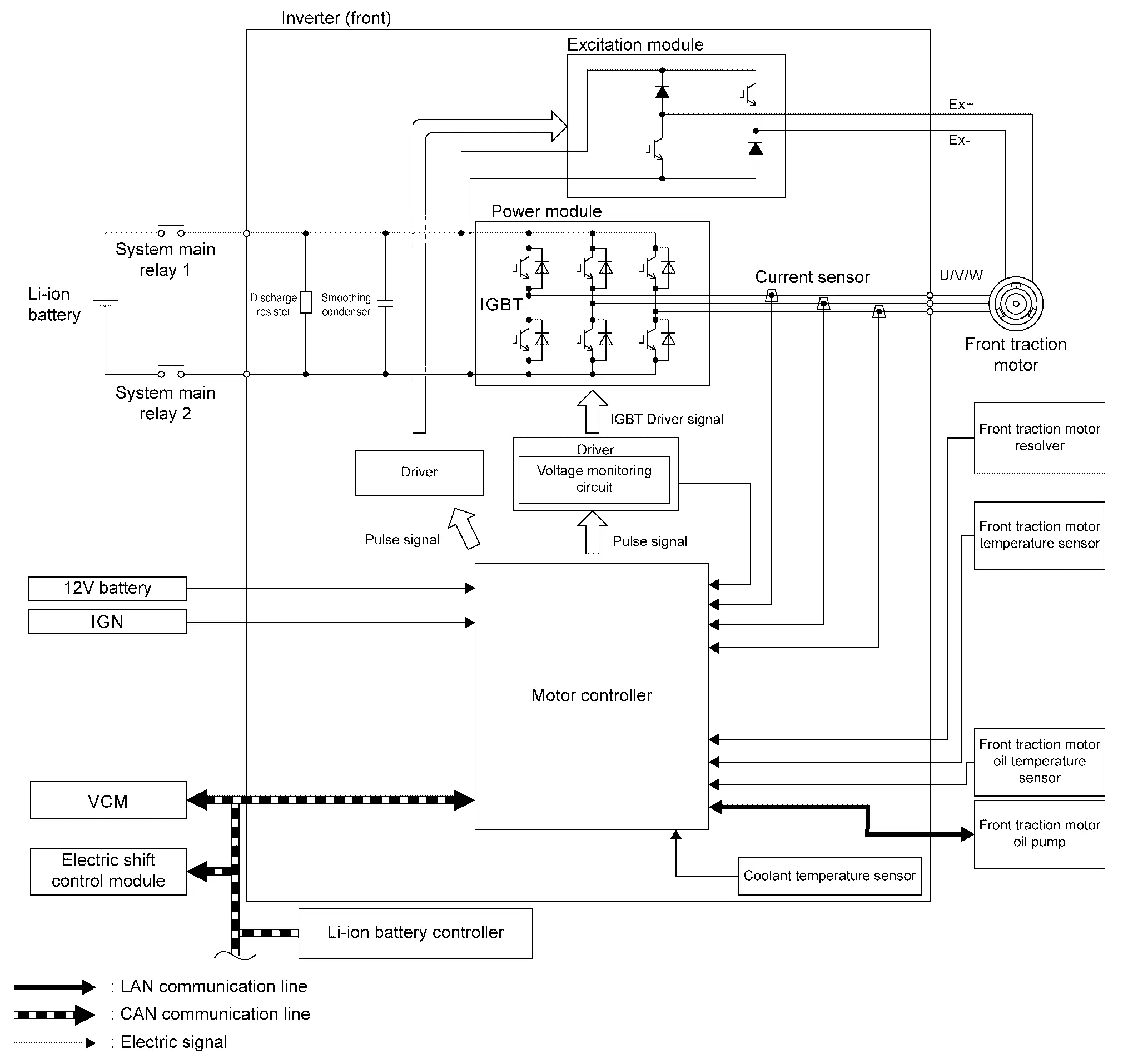
  • The inverter (front) controls the front traction motor based on the target motor torque signal transmitted by EV system CAN from the VCM.

  • Inverter (front) converts DC power from Li-ion battery to AC power, and drives front traction motor accurately based on resolver detection signal and current sensor detection signal.

  • At deceleration, front traction motor is used as generator. It converts kinetic energy generated by rotary motion of tires (AC power) to electric energy (DC power) and charges Li-ion battery.

  • If malfunction is detected, the system enters fail-safe mode. Refer to Fail-safe.

SYSTEM DIAGRAM
ComponentDescription
VCM
  • The inverter (front) transmits the following signals to the VCM via the EV system CAN.

    • Front motor speed signal

    • Front motor torque limit signal

    • Motor discharge status signal

    • Input high voltage signal

    • Coolant temperature sensor signal

  • The inverter (front) receives the following signals from the VCM via the EV system CAN.

    • HV battery relay ON permit signal

    • Inverter (front) operation command signal

    • Inverter (front) traction limitation signal

    • HV sleep wake up signal

    • Power switch ON signal

    • Coolant flow rate signal

    • Total mileage signal

    • Safety torque signal

    • Target front motor torque signal

    • Pulse signal OFF signal

    • System cut off signal

    • Vibration control switching signal

    • Motor discharge request signal

    • Regenerative torque command signal

LBC

The inverter (front) receives the following signals from the LBC via the EV system CAN.

  • HV battery total voltage signal

  • DTC signal

Front traction motor

  • Front traction motor resolver

  • Front traction motor temperature sensor

  • Front traction motor oil temperature sensor

  • Front traction motor oil pump

Refer to Component Description.

Inverter (front)

  • Motor controller

  • Driver

  • Power module

  • Excitation module

  • Smoothing condenser

  • Current sensor

  • Discharge resister

  • Power module temperature sensor

  • Driver print circuit board temperature sensor

  • Excitation print circuit board temperature sensor

  • Coolant temperature sensor

Refer to Component Description.

Circuit Diagram

Fail-safe

DTCEV system warning lampFail-safe and Nissan Ariya vehicle behavior
P030A 62 — —
P0A00 11 — Send coolant temperature that cannot be used to VCM
13 — Send coolant temperature that cannot be used to VCM
P0A1B 01 ON Control of the front traction motor stops. Or, the Nissan Ariya vehicle cannot be started (READY status cannot be achieved)
03 ON
04 ON
05 ON
44 — —
P0A2A 11 ON Send front traction motor temperature of 180 °C to the VCM
13 ON Send front traction motor temperature of 180 °C to the VCM
4B ON The driving torque of the front traction motor is limited to 0 N·m
P0A3F 04 ON Control of the front traction motor stops. Or, the Nissan Ariya vehicle cannot be started (READY status cannot be achieved)
1C ON
P0A51 01 ON Control of the front traction motor stops
P0A78 48 ON Limits drive torque of front traction motor
62 ON Control of the front traction motor stops. Or, no limitation
P0A8B A2 ON Control of the front traction motor stops
P0AED 11 — —
13 —
1C —
4B ON The driving torque of the front traction motor is limited to 0 N·m. Or, control of the front traction motor stops
P0BE5 1C ON The Nissan Ariya vehicle cannot be started (READY status cannot be achieved)
P0BE9 1C ON The Nissan Ariya vehicle cannot be started (READY status cannot be achieved)
P0BED 1C ON The Nissan Ariya vehicle cannot be started (READY status cannot be achieved)
P0BFF 11 ON Control of the front traction motor stops
12 ON
18 ON
P0C0B 01 ON Control of the front traction motor stops. Or, the Nissan Ariya vehicle cannot be started (READY status cannot be achieved)
04 ON
1C ON
A2 ON
P0CBC 11 ON —
13 ON —
4B ON The driving torque of the front traction motor is limited to 0 N·m
P0CC1 04 ON The driving torque of the front traction motor is limited to 30%
81 ON —
87 ON The driving torque of the front traction motor is limited to 30%
P0D2D 17 ON Control of the front traction motor stops
P0DA8 00 ON Control of the front traction motor stops
P161D 61 — The Nissan Ariya vehicle cannot be started (READY status cannot be achieved)
P161E 68 — The Nissan Ariya vehicle cannot be started (READY status cannot be achieved)
P161F 64 — The Nissan Ariya vehicle cannot be started (READY status cannot be achieved)
P2D3B 92 ON —
P2E28 01 ON Control of the front traction motor stops
18 ON
1D ON —
P2E2B 11 ON Control of the front traction motor stops
12 ON
1C ON
P3081 44 ON Change the resolver offset value to the default value. This reduces torque because optimal control of the rotor position is not possible
P3082 44 ON Change the rotor resistance value to the default value. This will make it more likely that torque will be limited for temperature protection
P3083 44 — —
U2143 82 May turn ON Nissan Ariya Vehicle stops (torque 0 N·m), or the driving torque of the front traction motor is limited, or is not limited
83 May turn ON
87 May turn ON
U2144 82 May turn ON The driving torque of the front traction motor is limited. Or, no limitation
83 May turn ON
87 May turn ON
U2150 87 — —

Protection Function

When temperature of inverter (front) or front traction motor components rises, the inverter (front) temporarily enters a protective control state in order to protect the system. It automatically returns to the normal status if the safety is secured.

ConditionControlNormal return condition
The front traction motor is overheated. The output torque from the front traction motor is restricted according to the temperature. The temperature has decreased to normal in the front traction motor.
The IGBT becomes hot.

The switching frequency in the IGBT is reduced.

The temperature has decreased.
The inside of the inverter, including the IGBT, is overheated. The output torque from the front traction motor is restricted according to the temperature. The temperature has decreased.

Front Traction Motor Power Control Nissan Ariya 1st generation

System Description

DESCRIPTION

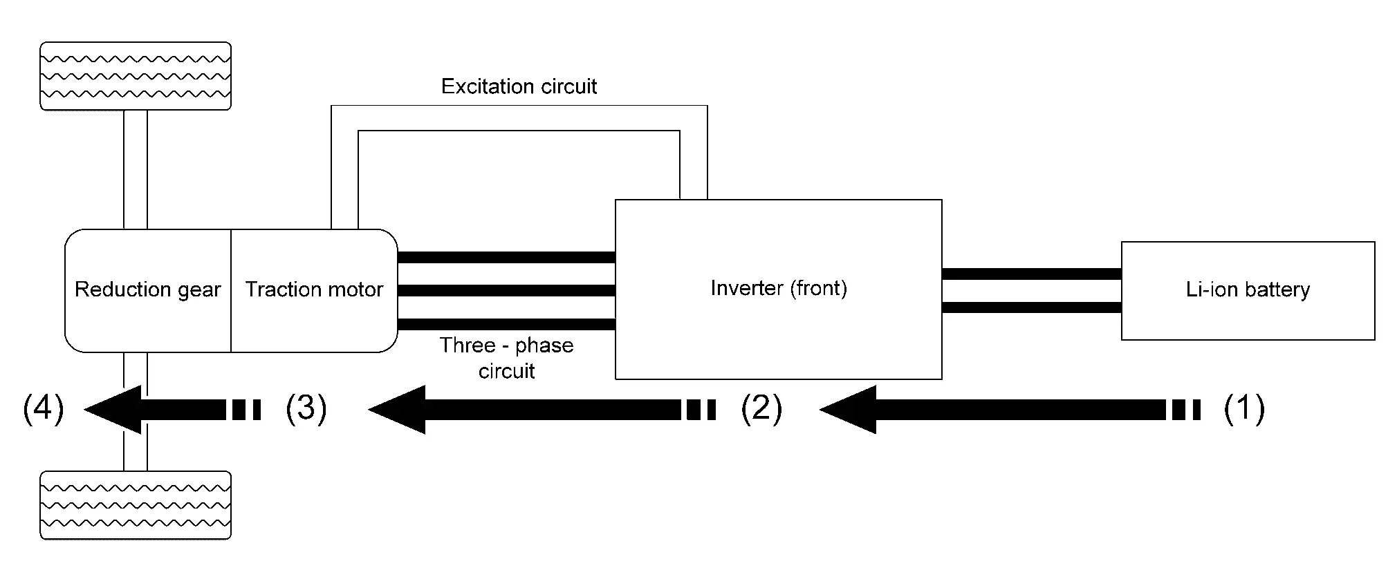
The inverter (front) applies AC power to the front traction motor according to the target motor torque signal calculated by VCM in order to generate drive force.

ENERGY FLOW
(4) ⇐ (3) ⇐ (2) ⇐ (1)
The driving torque from the front traction motor is used as motion energy for output from the Nissan Ariya vehicle. DC power sent from the inverter (front) to the rotor, and AC power sent to the stator, are transformed into magnetic energy and used to create a rotating magnetic field that generates driving torque. Switching actions in the inverter (front) (IGBT) convert DC power from the Li-ion battery into AC power. The DC power from the Li-ion battery is input to the inverter (front).

Front Traction Motor Regeneration Control Nissan Ariya 2023

System Description

DESCRIPTION

During deceleration, the inverter (front) drives the front traction motor to function as a generator based on the regenerative torque command signal sent via EV system CAN from the VCM, converting the kinetic torque generated by rotation of the tires into electrical energy. The converted electrical energy charges the Li-ion battery.

The regenerative torque that is generated when the front traction motor is driven as a generator can be used as braking force, acting similar to engine braking and reducing the burden on the service brakes.

FLOW OF ENERGY

(1) ⇒ (2) ⇒ (3) ⇒ (4)
The kinetic energy generated by rotation of the tires operates the front traction motor as a generator. AC power is generated using DC power sent from the inverter (front) to the rotor and rotation of the front traction motor. The IGBT in inverter (front) switches in order to convert the AC power from the front traction motor to DC power. The DC power regenerated by the inverter (front) is used to charge the Li-ion battery.