Back Door Closer Ecu
- Initialization
- Removal
- Installation
Initialization
INITIALIZATION
NOTICE:
Initialization of the multiplex network door ECU (back door initial position learning) is necessary if the following work procedures are performed while the back door is open.
- The cable to the negative (-) auxiliary battery terminal is connected.
- A power source system fuse of the power back door system is disconnected and reconnected.
- The multiplex network door ECU is replaced or the connectors are disconnected.
The power back door does not operate unless the multiplex network door ECU is initialized.
HINT:
- Initialization is not necessary if the above procedures are performed while the back door is closed.
- When disconnecting and reconnecting the auxiliary battery, there is an automatic learning function that completes learning when the respective system is used.
Click here


(a) Initialization operation
(1) Fully close the back door by hand.
Removal
REMOVAL
The necessary procedures (adjustment, calibration, initialization or registration) that must be performed after parts are removed and installed, or replaced during multiplex network door ECU removal/installation are shown below.
Necessary Procedures After Parts Removed/Installed/ReplacedReplaced Part or Performed Procedure | Necessary Procedures | Effect/Inoperative Function When Necessary Procedures are not Performed | Link |
|---|---|---|---|
|
Reset back door close position |
Power Back Door System |
 |
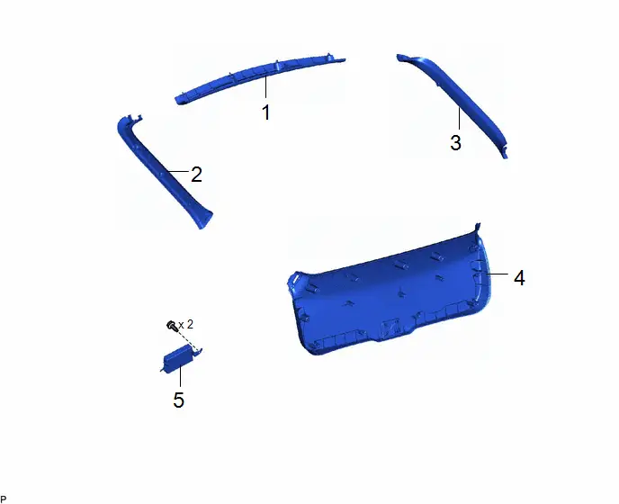
Procedure | Part Name Code |  |  |  |
|
|---|---|---|---|---|---|
1 |
BACK DOOR UPPER TRIM PANEL ASSEMBLY |
64790B |
- |
- |
- |
2 |
BACK DOOR SIDE GARNISH LH |
67938A |
- |
- |
- |
3 |
BACK DOOR SIDE GARNISH RH |
67937B |
- |
- |
- |
4 |
BACK DOOR TRIM BOARD ASSEMBLY |
67750 |
- |
- |
- |
5 |
MULTIPLEX NETWORK DOOR ECU |
89222A |
- |
- |
- |
PROCEDURE
1. REMOVE BACK DOOR UPPER TRIM PANEL ASSEMBLY
Click here 
2. REMOVE BACK DOOR SIDE GARNISH LH
Click here 
3. REMOVE BACK DOOR SIDE GARNISH RH
(a) Use the same procedure for the LH side.
4. REMOVE BACK DOOR TRIM BOARD ASSEMBLY
Click here 
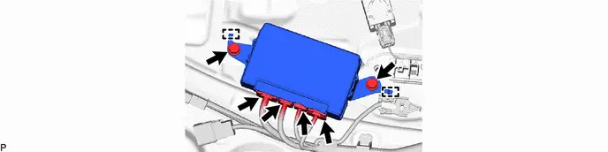
5. REMOVE MULTIPLEX NETWORK DOOR ECU
Installation
INSTALLATION
COMPONENTS (INSTALLATION)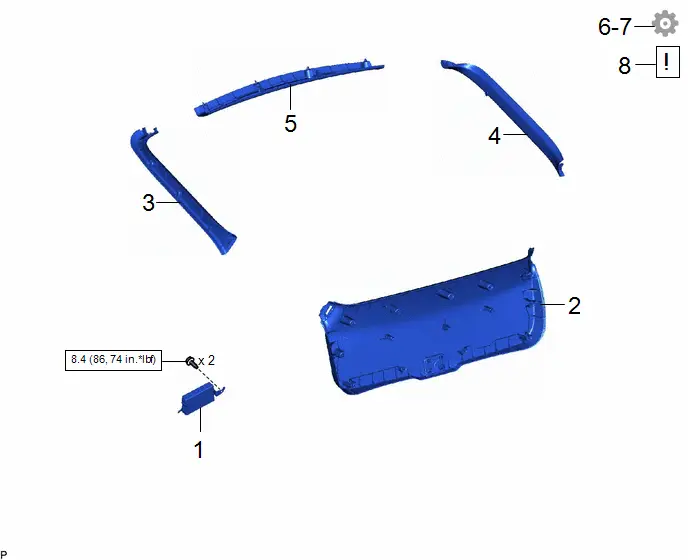
Procedure | Part Name Code |  |  |  |
|
|---|---|---|---|---|---|
1 |
MULTIPLEX NETWORK DOOR ECU |
89222A |
- |
- |
- |
2 |
BACK DOOR TRIM BOARD ASSEMBLY |
67750 |
- |
- |
- |
3 |
BACK DOOR SIDE GARNISH LH |
67938A |
- |
- |
- |
4 |
BACK DOOR SIDE GARNISH RH |
67937B |
- |
- |
- |
5 |
BACK DOOR UPPER TRIM PANEL ASSEMBLY |
64790B |
- |
- |
- |
6 |
INITIALIZE POWER BACK DOOR SYSTEM |
- |
- |
- |
 |
7 |
UPDATE ECU SECURITY KEY |
- |
- |
- |
 |
8 |
INSPECT POWER BACK DOOR SYSTEM |
- |
 |
- |
- |
 |
N*m (kgf*cm, ft.*lbf): Specified torque |
- |
- |
PROCEDURE
1. INSTALL MULTIPLEX NETWORK DOOR ECU
Torque:
8,4 N·m {86 kgf·cm, 74 in·lbf}
2. INSTALL BACK DOOR TRIM BOARD ASSEMBLY
3. INSTALL BACK DOOR SIDE GARNISH LH
4. INSTALL BACK DOOR SIDE GARNISH RH
5. INSTALL BACK DOOR UPPER TRIM PANEL ASSEMBLY
6. INITIALIZE POWER BACK DOOR SYSTEM
Click here 
7. UPDATE ECU SECURITY KEY
Click here 
8. INSPECT POWER BACK DOOR SYSTEM
 |
Click here |
