Rear Shock Absorber

In this manual: Rear Shock Absorber
How To Troubleshoot Ecu Controlled Systems — 1How To Use This Manual — 1Identification Information — 1Repair Instruction — 1Terms — 12zr-fxe Air Cleaner Filter Element — 12zr-fxe Auxiliary Battery — 12zr-fxe Coolant (for Engine Coolant) — 12zr-fxe Oil And Oil Filter — 12zr-fxe Spark Plug — 1Air Conditioning Filter — 1Battery Cooling Filter — 1Brake Fluid — 1Coolant (for Inverter) — 1Front Brake Flexible Hose — 1Front Disc Brake Pad — 1Front Lower Ball Joint — 1Front Wheel Alignment — 1Front Wiper Rubber — 1General Maintenance — 1M20a-fxs Air Cleaner Filter Element — 1M20a-fxs Auxiliary Battery — 1M20a-fxs Coolant (for Engine Coolant) — 1M20a-fxs Oil And Oil Filter — 1M20a-fxs Spark Plug — 1Pa10/pb10/pb12 Hybrid Transaxle Fluid — 1Q810 Hybrid Transaxle Fluid — 1Rear Brake Flexible Hose — 1Rear Disc Brake Pad — 1Rear Wheel Alignment — 1Steering Column — 1Tire And Wheel — 1Transmitter Battery — 1When Disconnecting Or Reconnecting Battery Terminal — 1When Replacing Or Removing/installing Parts — 1Automatic High Beam Main Switch — 1Automatic High Beam System — 1Driver Monitor Camera — 1Driver Monitor Camera System — 1Driver Monitor Ecu — 1Front Camera — 1Front Camera System — 1Front Radar Sensor System — 1Front Side Radar Sensor — 1Front Side Radar Sensor System — 1Millimeter Wave Radar Sensor — 1Utility — 1Advanced Park — 1Advanced Park Main Switch — 1Amplifier Antenna — 1Audio And Visual System — 1Front Door Speaker — 1Instrument Panel Speaker — 1Microphone — 1Noise Filter — 1Pillar Speaker — 1Radio Antenna Cord (for Back Door) — 1Radio Antenna Cord (for Instrument Panel) — 1Radio Antenna Cord (for Roof) — 1Radio Receiver — 1Rear Door Speaker — 1Roof Antenna — 1Stereo Component Amplifier — 1Stereo Jack Adapter Assembly — 1Window Glass Antenna Wire — 1Back-up Battery — 1Dcm(telematics Transceiver) — 1Manual(sos)switch — 1Safety Connect System — 1Telephone And Gps Antenna (for Front Side) — 1Telephone And Gps Antenna (for Roof Side) — 1Telephone And Gps Antenna Cords — 1Garage Door Opener System (for Digital Inner Mirror) — 1Garage Door Opener System (for Ec Inner Mirror) — 1Blind Spot Monitor Sensor — 1Blind Spot Monitor System — 1Clearance Warning Ecu — 1Intuitive Parking Assist System — 1Panoramic View Monitor Switch — 1Panoramic View Monitor System — 1Parking Assist Ecu — 1Parking Assist Light — 1Parking Assist Monitor System — 1Parking Support Brake System — 1Rear View Monitor System — 1Television Camera (for Front) — 1Television Camera (for Rear) — 1Television Camera (for Side) — 1Ultrasonic Sensor (for Front) — 1Ultrasonic Sensor (for Rear) — 1Brake Actuator — 1Brake Pedal Stroke Sensor — 1Electronically Controlled Brake System — 1Front Speed Sensor — 1Rear Speed Sensor (for Awd) — 1Steering Angle Sensor — 1Brake Booster — 1Brake Fluid — 1Brake Line — 1Brake Pedal — 1Brake System — 1Electric Parking Brake Actuator — 1Electric Parking Brake Switch — 1Electric Parking Brake System — 1Forced Release — 1Front Axle Hub — 1Front Axle Hub Bolt — 1Rear Axle Carrier (for 2wd) — 1Rear Axle Carrier (for Awd) — 1Rear Axle Hub (for 2wd) — 1Rear Axle Hub (for Awd) — 1Rear Axle Hub Bolt — 1Steering Knuckle — 1Drive Shaft System — 1Front Drive Shaft Assembly — 1Rear Drive Shaft Assembly — 1Combination Switch — 1Electronic Shift Lever System — 1Hybrid Transaxle Fluid — 1Hybrid Transaxle Oil Seal — 1Hybrid Transaxle System — 1Input Shaft Oil Seal — 1Motor Cable — 1Pa10 Hybrid Vehicle Transaxle — 1Pa10 Manual Parking Lock Release — 1Pa10 Oil Cooler — 1Pb10/pb12 Hybrid Vehicle Transaxle — 1Pb10/pb12 Manual Parking Lock Release — 1Pb10/pb12 Oil Cooler — 1Shift Control Actuator — 1Shift Lever — 1Shift Lever Knob — 1Differential Side Gear Shaft — 1Hybrid Transaxle Fluid — 1Hybrid Transaxle Side Gear Oil Seal — 1Motor Cable — 1Rear Traction Motor — 1Coolant (for Engine) — 1Cooling Fan Motor — 1Cooling Fan System — 1Radiator — 1Relay — 1Thermostat — 1Water Pump — 1Canister — 1Egr Cooler — 1Egr Valve — 1Emission Control System — 1Fuel Tank Cap — 1Pcv Valve — 1Purge Valve — 1Vacuum Sensor — 1Air Fuel Ratio Sensor — 1Camshaft Oil Control Valve — 1Camshaft Position Sensor — 1Crankshaft Position Sensor — 1Ecm — 1Engine Coolant Temperature Sensor — 1Heated Oxygen Sensor — 1Ignition Coil And Spark Plug — 1Ignition System — 1Knock Sensor — 1Mass Air Flow Meter — 1Relay — 1Sfi System — 1Throttle Body — 1Camshaft — 1Cylinder Block — 1Cylinder Head — 1Cylinder Head Gasket — 1Engine — 1Engine Assembly — 1Engine Unit — 1Front Crankshaft Oil Seal — 1Rear Crankshaft Oil Seal — 1Fuel Filter — 1Fuel Injector — 1Fuel Pressure Regulator — 1Fuel Pump — 1Fuel Sender Gauge Assembly — 1Fuel System — 1Fuel Tank — 1Air Cleaner Filter Element — 1Exhaust Manifold — 1Exhaust Pipe — 1Intake Manifold — 1Intake System — 1Lubrication System — 1Oil And Oil Filter — 1Oil Pan And Oil Level Sensor — 1Oil Pressure Switch — 1Oil Pump — 1Accelerator Pedal Sensor — 1Battery Blower (for Hev Model) — 1Battery Ecu (for Hev Model) — 1Battery Ecu (for Phev Model) — 1Battery Voltage Sensor (for Phev Model) — 1Charge Cable (for Phev Model) — 1Charge Indicator (for Phev Model) — 1Charge Inlet (for Phev Model) — 1Combination Switch — 1Coolant (for Inverter) — 1Cooler (for Phev Model) — 1Electric Vehicle Charger Assembly (for Phev Model) — 1Frame Wire (for Hev Model) — 1Frame Wire (for Phev Model) — 1Heater Relay (for Phev Model) — 1Hv Battery (for Hev Model) — 1Hv Battery (for Phev Model) — 1Hv Battery Heater (for Phev Model) — 1Hv Battery Stack (for Phev Model) — 1Hv Relay Assembly (for Hev Model) — 1Hv Relay Assembly (for Phev Model) — 1Hybrid Battery System (for 2zr-fxe) — 1Hybrid Battery System (for M20a-fxs) — 1Hybrid Battery System (for Phev Model) — 1Hybrid Vehicle Control Ecu — 1Inverter With Converter (for Hev Model) — 1Motor Generator Control System (for 2zr-fxe) — 1Plug-in Charge Control System (for Phev Model) — 1Refrigerant Line (for Phev Model) — 1Relay — 1Service Plug Grip (for Hev Model) — 1Sub Radiator — 1Water Pump With Motor — 1Auxiliary Battery — 1Battery Current Sensor — 1Charging System — 1Solar Charging System — 1Solar Control Unit — 1Solar Roof — 1Can Communication System (for Hev Model) — 1Lin Communication System — 1Network Gateway Ecu — 1Integration Control Supply — 1Main Body Ecu — 1Power Integration System — 1Sub Battery System — 1Power Steering Ecu — 1Power Steering System — 1Heated Steering Wheel Controller — 1Heated Steering Wheel System — 1Steering Column Assembly — 1Steering Heater Switch — 1Steering Pad Switch — 1Steering System — 1Steering Wheel — 1Front Lower Ball Joint — 1Front Lower Suspension Arm (for 2zr-fxe Lh Side) — 1Front Lower Suspension Arm (for 2zr-fxe Rh Side) — 1Front Lower Suspension Arm (for M20a-fxs) — 1Front Shock Absorber — 1Front Stabilizer Bar — 1Front Suspension Member — 1Rear Coil Spring — 1Rear Lower Arm (for Awd Lh Side) — 1Rear Lower Arm (for Awd Rh Side) — 1Rear Lower Arm (for Hev Model 2wd) — 1Rear Lower Arm (for Phev Model) — 1Rear Shock Absorber — 1Rear Stabilizer Bar — 1Rear Suspension Member (for 2wd) — 1Rear Suspension Member (for Awd) — 1Rear Trailing Arm — 1Rear Upper Arm — 1Tire And Wheel System — 1Tire Repair Seal — 1Tire Pressure Warning Receiver — 1Tire Pressure Warning System — 1Tire Pressure Warning Valve — 1Acoustic Vehicle Alerting System — 1Vehicle Approaching Speaker — 1Vehicle Approaching Speaker Ecu — 1Back Door — 1Back Door Closer Ecu — 1Back Door Opener Switch — 1Back Door Support — 1Back Door Weatherstrip — 1Charge Lid Courtesy Switch — 1Charge Lid Opener Motor Assembly — 1Charge Lid Opener System — 1Charge Lid Opener Unit — 1Front Door — 1Front Door Opening Trim Weatherstrip — 1Fuel Lid Opener Motor Assembly — 1Fuel Lid Opener Switch — 1Fuel Lid Opener System — 1Hood — 1Hood Lock Control Cable Assembly — 1Power Back Door Closer Switch — 1Power Back Door Control Switch — 1Power Back Door Drive Unit — 1Power Back Door System — 1Power Back Door Touch Sensor — 1Power Back Door Warning Buzzer — 1Rear Door — 1Rear Door Opening Trim Weatherstrip — 1Reserve Lock Switch — 1Front Bumper — 1Front Door Belt Moulding — 1Front Door Window Frame Moulding — 1Front Fender — 1Front Pillar Upper Cover — 1Grille Shutter — 1Grille Shutter System — 1Name Plate — 1Quarter Garnish — 1Rear Bumper — 1Rear Door Belt Moulding — 1Rear Door Window Frame Moulding — 1Rear Wheel House Plate — 1Rocker Panel Moulding — 1Roof Drip Side Finish Moulding — 1Roof Garnish — 1Wheel Opening Moulding (for Front Side) — 1Wheel Opening Moulding (for Rear Side) — 1Windshield Outside Moulding — 1Horn — 1Horn System — 1Relay — 1Automatic Light Control Sensor — 1Back-up Light Assembly — 1Charge Lid Light — 1Front Marker Light — 1Hazard Warning Switch — 1Headlight Assembly — 1Headlight Dimmer Switch — 1Headlight Leveling Switch — 1High Mounted Stop Light Assembly — 1Illumination Light Assembly — 1License Plate Light Assembly — 1Lighting System — 1Rear Combination Light Assembly — 1Rear Light Assembly — 1Rear Side Marker Light Assembly — 1Relay — 1Side Turn Signal Light Assembly — 1Stop Light Switch — 1Switch Housing — 1Outer Mirror Switch — 1Outer Rear View Mirror — 1Outer Rear View Mirror Cover — 1Outer Rear View Mirror Glass — 1Power Mirror Control System — 1Back Door Glass — 1Front Passenger Side Power Window Switch — 1Power Window Control System — 1Power Window Master Switch — 1Power Window Regulator Motor (for Front Door) — 1Power Window Regulator Motor (for Rear Door) — 1Rear Power Window Switch — 1Relay — 1Roof Window Fix Glass — 1Window Defogger System — 1Windshield Deicer Switch — 1Windshield Deicer System — 1Windshield Glass — 1Front Wiper Motor — 1Rain Sensor — 1Relay — 1Washer Motor — 1Washer Nozzle (for Front Side) — 1Washer Nozzle (for Rear Television Camera) — 1Wiper And Washer System — 1Wiper Ecu — 1Wiper Switch — 1Back Door Lock — 1Door Control Receiver — 1Door Control Switch — 1Door Control Transmitter — 1Door Lock Release Motor (for Rear Side) — 1Door Outside Handle (for Rear Side) — 1Front Door Lock — 1Power Door Lock Control System — 1Rear Door Lock — 1Transmitter Battery — 1Wireless Door Lock Control System — 1Accumulator — 1Air Conditioning Amplifier — 1Air Conditioning Panel — 1Air Conditioning Pressure Sensor — 1Air Conditioning Unit — 1Ambient Temperature Sensor — 1Blower Unit — 1Condenser (for Hev Model) — 1Condenser (for Phev Model) — 1Discharge Temperature Sensor — 1Electric Expansion Valve (cooling) — 1Electric Expansion Valve (heating) — 1Evaporator Pipe Temperature Sensor — 1Evaporator Pressure Regulator — 1Front Blower Motor — 1Front Evaporator Front Solenoid Valve — 1Air Conditioning System (for Hev Model) — 1Front Evaporator Temperature Sensor — 1Heat Exchanger Temperature Sensor — 1Heat Pump Ecu — 1High Pressure Magnetic Valve — 1Humidity Sensor — 1Internal Condenser Temperature Sensor — 1Low Pressure Magnetic Valve — 1Refrigerant (for Hfc-134a(r134a)) — 1Refrigerant Line (for Hev Model) — 1Refrigerant Line (for Phev Model) — 1Relay — 1Room Temperature Sensor — 1Solar Sensor — 1Floor Carpet — 1Front Console Box — 1Instrument Panel Safety Pad — 1Roof Headlining — 1Roof Sunshade — 1Ambient Light (for Driver Side) — 1Ambient Light (for Front Passenger Side) — 1Back Door Courtesy Switch — 1Footwell Light — 1Glove Box Light — 1Lighting System — 1Luggage Compartment Room Light — 1Personal Light — 1Room Light — 1Vanity Light — 1Vanity Light Switch — 1Combination Meter — 1Meter / Gauge System — 1Trip Switch — 1Digital Inner Mirror — 1Digital Rear-view Mirror System — 1Inner Mirror Monitor Camera — 1Inner Rear View Mirror (w/o Ec Mirror) — 1Accessory Power Outlet System — 1Power Outlet Socket (for Console Box Front Side) — 1Power Outlet Socket (for Console Box Rear Side) — 1Power Outlet Socket (for Console Box) — 1Power Outlet Socket (for Luggage Compartment) — 1Power Outlet Switch — 1Wireless Charger Assembly — 1Wireless Charging System — 1Climate Control Seat System — 1Front Power Seat Control System (w/ Memory) — 1Front Power Seat Motor Assembly — 1Front Seat Assembly (for Power Seat) — 1Front Seat Cushion Heater (for Power Seat) — 1Front Seatback Heater (for Power Seat) — 1Lumbar Support Adjuster Assembly — 1Power Seat Control Ecu — 1Power Seat Switch — 1Power Seat Track Rail Assembly — 1Rear Seat Assembly — 1Rear Seat Cushion Heater — 1Rear Seat Reminder System — 1Rear Seatback Heater — 1Seat Heater Control — 1Seat Heater Switch (for Front Seat) — 1Seat Heater Switch (for Rear Side) — 1Seat Heater System — 1Seat Memory Switch — 1Child Restraint Seat Anchor Bracket — 1Front Seat Inner Belt Assembly — 1Front Seat Outer Belt Assembly — 1Occupant Detection Sensor (for Front Passenger Side) — 1Rear Center Seat Outer Belt Assembly — 1Rear Seat Inner Belt Assembly (for Rh Side) — 1Rear Seat Outer Belt Assembly — 1Seat Belt Warning System (w/ Occupant Classification System) — 1Tongue Plate Stopper — 1Airbag System — 1Center Airbag Sensor Assembly — 1Curtain Shield Airbag Assembly — 1Front Airbag Sensor — 1Front Passenger Airbag Assembly — 1Front Seat Side Airbag Assembly — 1Inspection After Collision — 1Knee Airbag Assembly — 1Occupant Classification System — 1Rear Seat Side Airbag Assembly — 1Side Airbag Sensor (for Center Pillar) — 1Side Airbag Sensor (for Front Door) — 1Spiral Cable — 1Steering Pad — 1Certification Ecu — 1Digital Key Ecu — 1Digital Key Receiver (for Front Floor) — 1Digital Key Receiver (for Outside Luggage Compartment) — 1Digital Key Receiver (for Rear Door) — 1Digital Key System — 1Electrical Key Oscillator (for Front Floor) — 1Electrical Key Oscillator (for Outside Luggage Compartment) — 1Electrical Key Oscillator (for Rear Floor) — 1Engine Hood Courtesy Switch — 1Id Code Box — 1Smart Key System (for Start Function) — 1
~10min read
1special tools
010203040502518N·mlb·ft
Tightening torque found on this page
  • Removal
  • Inspection
  • Installation
  • Disposal

Removal

REMOVAL

The necessary procedures (adjustment, calibration, initialization, or registration) that must be performed after parts are removed and installed, or replaced during rear shock absorber assembly removal/installation are shown below.

Necessary Procedures After Parts Removed/Installed/Replaced

Replaced Part or Performed Procedure

Necessary Procedure

Effect/Inoperative Function when Necessary Procedure not Performed

Link

*1: Also necessary after performing a tire rotation.

*2: It is not necessary to perform this procedure if the tire pressure warning valve and transmitters are installed to the same location.

*3: The Toyota Prius vehicle height changes because of suspension or tire replacement.

Rear wheel alignment adjustment

Perform "Calibration"

  • DTCs are stored
  • ABS warning light illuminates
  • Brake system warning light (yellow indicator) illuminates
  • Slip indicator light illuminates
  • Electronically controlled brake system disabled or malfunctions

Tires

  • Initialization*1*2
  • Tire Position Identification*1*2

Tire Pressure Warning System

Refer to Procedures Necessary When Replacing Parts (for Tire Pressure Warning System)

Rear television camera assembly optical axis (Back camera position setting)*3

Parking Assist Monitor System

Parking assist ECU initialization*3

Panoramic View Monitor System

Advanced Park

Suspension parts

Rear television camera assembly optical axis (Back camera position setting)

Parking Assist Monitor System

Parking assist ECU initialization

Panoramic View Monitor System

Advanced Park

HINT:

  • Use the same procedure for the RH and LH sides.
  • The following procedure is for the LH side.
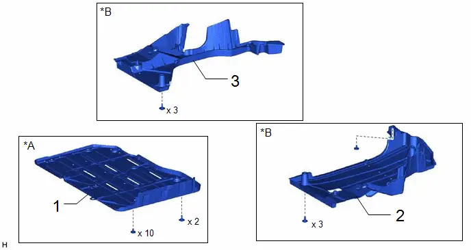
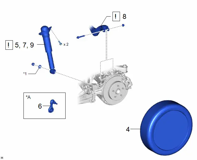
COMPONENTS (REMOVAL)

Procedure

Part Name Code

1

BATTERY BOX COVER

58219K

-

-

-

2

REAR FLOOR SIDE MEMBER COVER LH

57628E

-

-

-

3

REAR FLOOR SIDE MEMBER COVER RH

57627G

-

-

-

*A

for PHEV Model

*B

for HEV Model

Procedure

Part Name Code

4

REAR WHEEL

-

-

-

-

5

LOOSEN REAR SHOCK ABSORBER ASSEMBLY

48540

-

-

6

REAR STABILIZER LINK ASSEMBLY

48840A

-

-

-

7

SEPARATE REAR SHOCK ABSORBER ASSEMBLY

48540

-

-

8

REAR UPPER CONTROL ARM ASSEMBLY

48790

-

-

9

REMOVE REAR SHOCK ABSORBER ASSEMBLY

48540

-

-

*A

w/ Stabilizer Bar

-

-

*1

PLATE WASHER

-

-

Procedure

Part Name Code

10

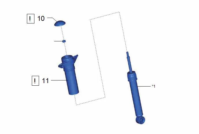
REAR SHOCK ABSORBER CAP

48554A

-

-

11

REAR SUSPENSION SUPPORT ASSEMBLY

48760B

-

-

*1

REAR SHOCK ABSORBER ASSEMBLY

-

-

●

Non-reusable part

★

Precoated part

PROCEDURE

1. REMOVE BATTERY BOX COVER (for PHEV Model)

Click here

2. REMOVE REAR FLOOR SIDE MEMBER COVER LH (for HEV Model)

Click here

3. REMOVE REAR FLOOR SIDE MEMBER COVER RH (for HEV Model)

Click here

4. REMOVE REAR WHEEL

Click here

5. LOOSEN REAR SHOCK ABSORBER ASSEMBLY
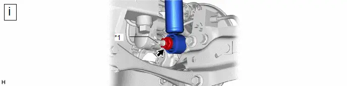
*1

Rear Axle Carrier Pin

-

-

(1) Loosen the nut of the rear shock absorber assembly.

NOTICE:

Hold the rear axle carrier pin while rotating the nut.

6. REMOVE REAR STABILIZER LINK ASSEMBLY (w/ Stabilizer Bar)

Click here

7. SEPARATE REAR SHOCK ABSORBER ASSEMBLY
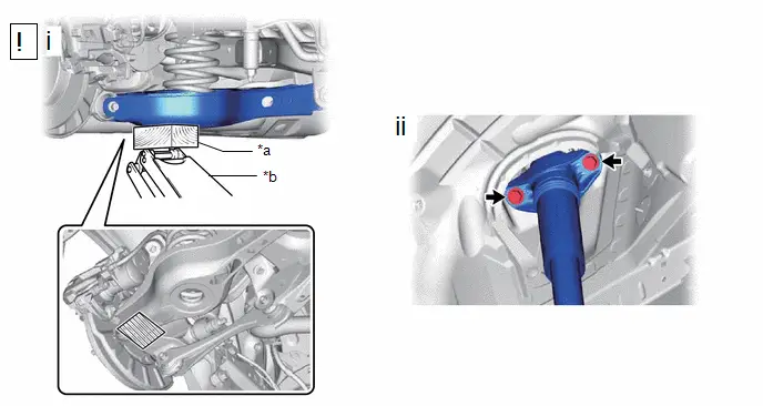
*a

Wooden Block

*b

Jack

Wooden Block Placement Location

-

-

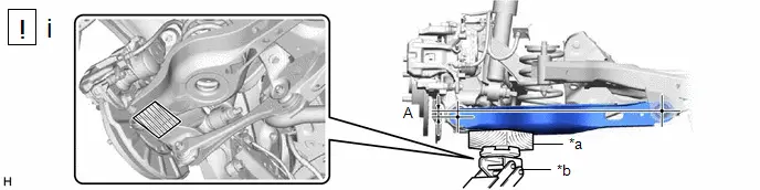
(1) Using a jack and wooden block, support the rear No. 2 suspension arm assembly.

NOTICE:

  • When jacking up the rear No. 2 suspension arm assembly, be sure to jack it up slowly.
  • Make sure to perform this operation with the Toyota Prius vehicle kept as low as possible.

(2) Remove the 2 bolts and separate the rear shock absorber assembly from the vehicle.

8. SEPARATE REAR UPPER CONTROL ARM ASSEMBLY
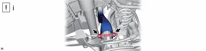
(1) Remove the bolt and nut, and separate the rear upper control arm assembly from the rear axle carrier sub-assembly.

NOTICE:

Because the nut has its own stopper, do not turn the nut. Loosen the bolt with the nut secured.

9. REMOVE REAR SHOCK ABSORBER ASSEMBLY
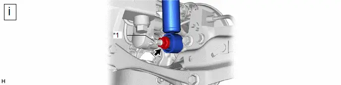
*1

Rear Axle Carrier Pin

-

-

(1) Remove the nut, plate washer and rear shock absorber assembly from the rear axle carrier sub-assembly.

NOTICE:

Hold the rear axle carrier pin while rotating the nut.

10. REMOVE REAR SHOCK ABSORBER CAP
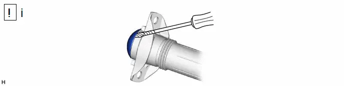
(1) Using a screwdriver with its tip wrapped with protective tape, remove the rear shock absorber cap from the rear shock absorber assembly.

11. REMOVE REAR SUSPENSION SUPPORT ASSEMBLY
*a

Turn

*b

Hold

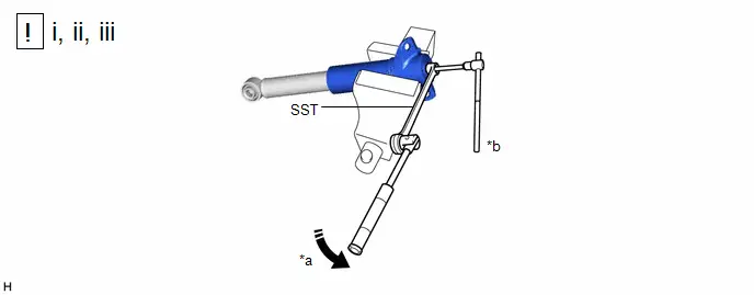
(1) Secure the rear shock absorber assembly in a vise using aluminum plates.

NOTICE:

Do not overtighten the vise.

(2) Using SST and a 6 mm hexagon socket wrench, hold the rear shock absorber rod and remove the rear support to rear shock absorber nut.

SST: 09729-00170

(3) Remove the rear suspension support assembly from the rear shock absorber assembly.

Inspection

INSPECTION

PROCEDURE

1. INSPECT REAR SHOCK ABSORBER ASSEMBLY

(a) Compress and extend the rear shock absorber assembly rod 4 or more times.

Standard:

When compressed and extended at a constant speed, the stroke of the shock absorber rod is smooth with no abnormal resistance or sounds. When extended, the shock absorber rod returns to its original position at a constant speed with no abnormal sounds.

(b) If there are any abnormalities, replace the rear shock absorber assembly with a new one.

Installation

INSTALLATION

HINT:

  • Use the same procedure for the RH side and LH side.
  • The following procedure is for the LH side.
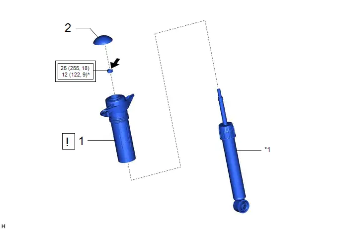
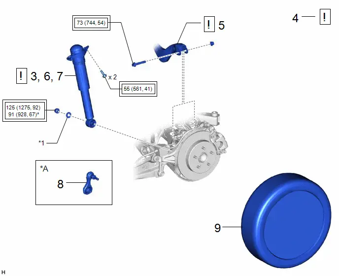
COMPONENTS (INSTALLATION)

Procedure

Part Name Code

1

REAR SUSPENSION SUPPORT ASSEMBLY

48760B

-

-

2

REAR SHOCK ABSORBER CAP

48554A

-

-

-

*1

REAR SHOCK ABSORBER ASSEMBLY

-

-

Tightening torque for "Major areas involving basic Toyota Prius vehicle performance such as moving/turning/stopping": N*m (kgf*cm, ft.*lbf)

*

For use with SST

●

Non-reusable part

Adhesive 1324

★

Precoated part

-

-

Procedure

Part Name Code

3

TEMPORARILY INSTALL REAR SHOCK ABSORBER ASSEMBLY

48540

-

-

4

STABILIZE SUSPENSION

-

-

-

5

REAR UPPER CONTROL ARM ASSEMBLY

48790

-

-

6

CONNECT REAR SHOCK ABSORBER ASSEMBLY

48540

-

-

7

INSTALL REAR SHOCK ABSORBER ASSEMBLY

48540

-

-

8

REAR STABILIZER LINK ASSEMBLY (w/ Stabilizer Bar)

48840A

-

-

-

9

REAR WHEEL

-

-

-

-

*A

w/ Stabilizer Bar

-

-

*1

PLATE WASHER

-

-

Tightening torque for "Major areas involving basic Toyota Prius vehicle performance such as moving/turning/stopping": N*m (kgf*cm, ft.*lbf)

-

-

*

For use with a ball joint lock nut wrench

-

-

Procedure

Part Name Code

10

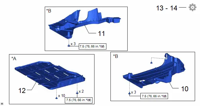
REAR FLOOR SIDE MEMBER COVER LH

57628E

-

-

-

11

REAR FLOOR SIDE MEMBER COVER RH

57627G

-

-

-

12

BATTERY BOX COVER

58219K

-

-

-

13

INSPECT AND ADJUST REAR WHEEL ALIGNMENT

-

-

-

14

PERFORM INITIALIZATION

-

-

-

*A

for PHEV Model

*B

for HEV Model

N*m (kgf*cm, ft.*lbf): Specified torque

-

-

PROCEDURE

1. INSTALL REAR SUSPENSION SUPPORT ASSEMBLY
*a

Torque Wrench Fulcrum Length

*b

Turn

*c

Hold

-

-

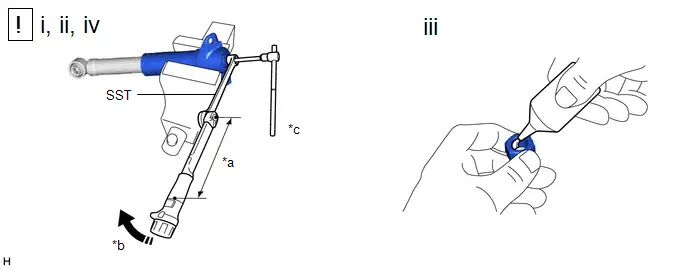
(1) Secure the rear suspension support assembly in a vise using aluminum plates.

NOTICE:

Do not overtighten the vise.

(2) Install the rear suspension support assembly to the rear shock absorber assembly.

(3) Apply a few drops of adhesive to the threads of a new rear support to rear shock absorber nut.

Adhesive:

Toyota Genuine Adhesive 1324, Three Bond 1324 or equivalent

(4) Using SST and a 6 mm hexagon socket wrench, hold the rear shock absorber rod and tighten the rear support to rear shock absorber nut.

SST: 09729-00170

Torque:

Specified tightening torque :

25 N·m {255 kgf·cm, 18 ft·lbf}

NOTICE:

Securely insert the 6 mm hexagon socket wrench into the rear shock absorber rod to prevent damage to the rear shock absorber assembly when tightening the rear support to rear shock absorber nut.

HINT:

  • Calculate the torque wrench reading when changing the fulcrum length of the torque wrench.

    Click here

  • When using SST (fulcrum length of 200 mm (7.87 in.)) torque wrench (fulcrum length of 180 mm (7.09 in.)):

    12 N*m (122 kgf*cm, 9 ft.*lbf)

2. INSTALL REAR SHOCK ABSORBER CAP

3. TEMPORARILY INSTALL REAR SHOCK ABSORBER ASSEMBLY
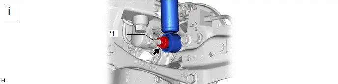
*1

Rear Axle Carrier Pin

-

-

(1) Temporarily install the rear shock absorber assembly to the rear axle carrier sub-assembly with the nut and plate washer.

NOTICE:

Hold the rear axle carrier pin while rotating the nut.

4. STABILIZE SUSPENSION

CAUTION:

Do not jack up the rear No. 2 suspension arm assembly too high as the Toyota Prius vehicle may fall.

*a

Wooden Block

*b

Jack

Wooden Block Placement Location

-

-

(1) Using a jack and wooden block, apply load to the suspension so that the rear No. 2 suspension arm assembly is positioned as shown in the illustration.

Standard Length (A):

13 mm (0.512 in.)

NOTICE:

  • When jacking up the rear No. 2 suspension arm assembly, be sure to jack it up slowly.
  • Make sure to perform this operation with the Toyota Prius vehicle kept as low as possible.

5. INSTALL REAR UPPER CONTROL ARM ASSEMBLY
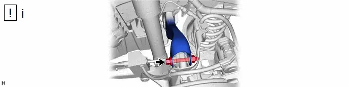
(1) Install the rear upper control arm assembly to the rear axle carrier sub-assembly with the bolt and nut.

Torque:

73 N·m {744 kgf·cm, 54 ft·lbf}

NOTICE:

  • Insert the bolt with the threaded end facing the rear of the Toyota Prius vehicle.
  • Because the nut has its own stopper, do not turn the nut. Tighten the bolt with the nut secured.

6. CONNECT REAR SHOCK ABSORBER ASSEMBLY
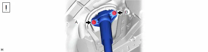
(1) Connect the rear shock absorber assembly to the vehicle with the 2 bolts.

Torque:

55 N·m {561 kgf·cm, 41 ft·lbf}

NOTICE:

Temporarily tighten the bolt (A) and then fully tighten the 2 bolts in the order of (B) and (A).

7. INSTALL REAR SHOCK ABSORBER ASSEMBLY
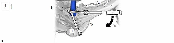
*1

Rear Axle Carrier Pin

-

-

*a

Torque Wrench Fulcrum Length

*b

Ball Joint Lock Nut Wrench

*c

Turn

*d

Hold

(1) Using a ball joint lock nut wrench, fully tighten the rear shock absorber assembly with the nut.

Torque:

Specified tightening torque :

125 N·m {1275 kgf·cm, 92 ft·lbf}

NOTICE:

Hold the rear axle carrier pin while rotating the nut.

HINT:

  • Calculate the torque wrench reading when changing the fulcrum length of the torque wrench.

    Click here

  • When using a ball joint lock nut wrench (fulcrum length of 149.75 mm (5.90 in.)) torque wrench (fulcrum length of 400 mm (1.31 ft.)):

    91 N*m (928 kgf*cm, 67 ft.*lbf)

8. INSTALL REAR STABILIZER LINK ASSEMBLY (w/ Stabilizer Bar)

Click here

9. INSTALL REAR WHEEL

Click here

10. INSTALL REAR FLOOR SIDE MEMBER COVER LH (for HEV Model)

Click here

11. INSTALL REAR FLOOR SIDE MEMBER COVER RH (for HEV Model)

Click here

12. INSTALL BATTERY BOX COVER (for PHEV Model)

Click here

13. INSPECT AND ADJUST REAR WHEEL ALIGNMENT

Click here

14. PERFORM INITIALIZATION

Parking Assist Monitor System

Panoramic View Monitor System

Advanced Park

Disposal

DISPOSAL

PROCEDURE

1. DISPOSE OF REAR SHOCK ABSORBER ASSEMBLY

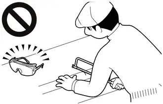
CAUTION:

  • Always use a cloth to prevent shards of metal flying about due to the release of pressurized gas.
  • Always wear safety glasses.

HINT:

The gas is colorless, odorless and non-poisonous.

(a) Extend the piston rod and secure the rear shock absorber assembly at an angle in a vise.

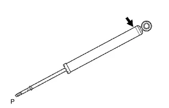
(b) Using a hacksaw, slowly make a hole at the position indicated by the arrow in the illustration to discharge the gas inside.