Refrigerant Line (for Phev Model)
- Removal
- Installation
- Airtight Inspection
Removal
REMOVAL
The necessary procedures (adjustment, calibration, initialization, or registration) that must be performed after parts are removed and installed, or replaced during the traction battery cooler tube removal/installation are shown below.
CAUTION:
- Orange wire harnesses and connectors indicate high-voltage circuits. To prevent electric shock, always follow the procedure described in the repair manual.
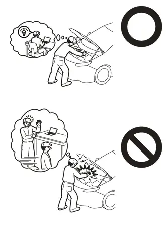
Click here

- To prevent electric shock, wear insulated gloves when working on wire harnesses and components of the high voltage system.
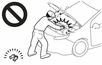
NOTICE:
After turning the ignition switch off, waiting time may be required before disconnecting the cable from the negative (-) auxiliary battery terminal.
Click here 
HINT:
When the cable is disconnected / reconnected to the auxiliary battery terminal, systems temporarily stop operating. However, each system has a function that completes learning the first time the system is used.
Items for which learning is completed by driving the Toyota Prius vehicleEffect/Inoperative Function when Necessary Procedure not Performed | Necessary Procedure | Link |
|---|---|---|
Front Camera System |
Drive the Toyota Prius vehicle straight ahead at 35 km/h or more for 5 seconds or more. |
 |
Effect/Inoperative Function when Necessary Procedure not Performed | Necessary Procedure | Link |
|---|---|---|
| *1: w/o Power Back Door System *2: w/ Power Back Door System |
||
Power Door Lock Control System*1
|
Perform door unlock operation with door control switch or electrical key transmitter sub-assembly switch. |
 |
Power Back Door System*2 |
Reset back door close position |
 |
Air Conditioning System |
After the ignition switch is turned to ON, the servo motor and expansion valve standard position is recognized. |
- |
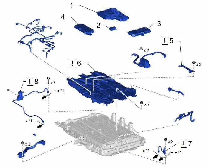
Procedure | Part Name Code |  |  |  |
|
|---|---|---|---|---|---|
1 |
NO. 1 TRACTION BATTERY DEVICE BOX ASSEMBLY |
- |
- |
- |
- |
2 |
NO. 1 TRACTION BATTERY HEATER RELAY |
G96J1 |
- |
- |
- |
3 |
BATTERY VOLTAGE SENSOR |
89892A |
- |
- |
- |
4 |
BATTERY ECU ASSEMBLY |
89890A |
- |
- |
- |
5 |
NO. 14 TRACTION BATTERY BRACKET |
G963E |
 |
- |
- |
6 |
NO. 10 TRACTION BATTERY BRACKET |
G963A |
 |
- |
- |
7 |
NO. 2 TRACTION BATTERY COOLER TUBE |
G96N2 |
 |
- |
- |
8 |
NO. 1 TRACTION BATTERY COOLER TUBE |
G96N1 |
 |
- |
- |
*1 |
O-RING |
- |
- |
● |
Non-reusable part |
 |
Compressor oil ND-OIL 11 or equivalent |
PROCEDURE
1. REMOVE NO. 1 TRACTION BATTERY DEVICE BOX ASSEMBLY
Click here 
2. REMOVE NO. 1 TRACTION BATTERY HEATER RELAY
Click here 
3. REMOVE BATTERY VOLTAGE SENSOR
Click here 
4. REMOVE BATTERY ECU ASSEMBLY
Click here 
5. REMOVE NO. 14 TRACTION BATTERY BRACKET
 |
CAUTION: Be sure to wear insulated gloves and protective goggles. |
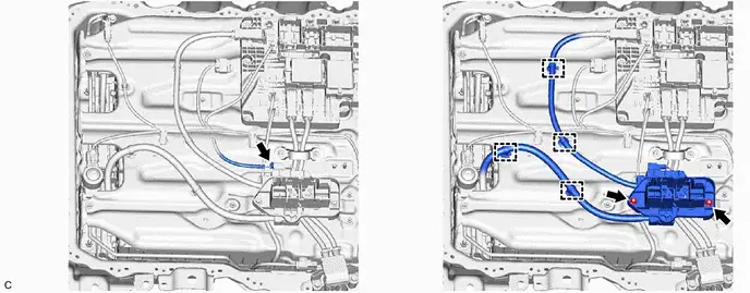

6. REMOVE NO. 10 TRACTION BATTERY BRACKET
 |
CAUTION: Be sure to wear insulated gloves and protective goggles. |
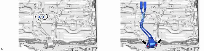
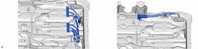
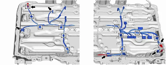
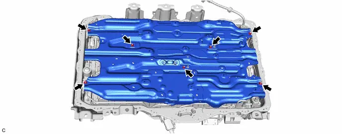
7. REMOVE NO. 2 TRACTION BATTERY COOLER TUBE
 |
CAUTION: Be sure to wear insulated gloves and protective goggles. NOTICE: Do not apply excessive force to the pipe. |

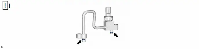
(1) Remove the 2 O-rings from the No. 2 traction battery cooler tube.
NOTICE:
Seal the openings of the disconnected parts with vinyl tape to prevent entry of moisture and foreign matter.
8. REMOVE NO. 1 TRACTION BATTERY COOLER TUBE
 |
CAUTION: Be sure to wear insulated gloves and protective goggles. NOTICE: Do not apply excessive force to the pipe. |
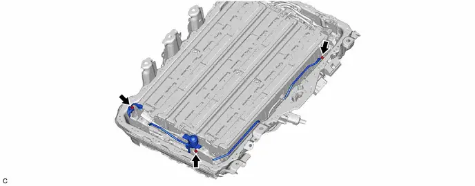
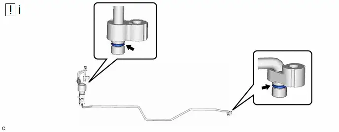
(1) Remove the 2 O-rings from the No. 1 traction battery cooler tube.
NOTICE:
Seal the openings of the disconnected parts with vinyl tape to prevent entry of moisture and foreign matter.
Installation
INSTALLATION
COMPONENTS (INSTALLATION)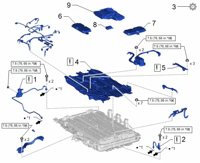
Procedure | Part Name Code |  |  |  |
|
|---|---|---|---|---|---|
1 |
NO. 1 TRACTION BATTERY COOLER TUBE |
G96N1 |
 |
- |
- |
2 |
NO. 2 TRACTION BATTERY COOLER TUBE |
G96N2 |
 |
- |
- |
3 |
INSPECT FOR REFRIGERANT LEAK |
- |
- |
- |
 |
4 |
NO. 10 TRACTION BATTERY BRACKET |
G963A |
 |
- |
- |
5 |
NO. 14 TRACTION BATTERY BRACKET |
G963E |
 |
- |
- |
6 |
BATTERY ECU ASSEMBLY |
89890A |
- |
- |
- |
7 |
BATTERY VOLTAGE SENSOR |
89892A |
- |
- |
- |
8 |
NO. 1 TRACTION BATTERY HEATER RELAY |
G96J1 |
- |
- |
- |
9 |
NO. 1 TRACTION BATTERY DEVICE BOX ASSEMBLY |
- |
- |
- |
- |
*1 |
O-RING |
- |
- |
 |
N*m (kgf*cm, ft.*lbf): Specified torque |
 |
Compressor oil ND-OIL 11 or equivalent |
● |
Non-reusable part |
- |
- |
PROCEDURE
1. INSTALL NO. 1 TRACTION BATTERY COOLER TUBE
 |
CAUTION: Be sure to wear insulated gloves and protective goggles. NOTICE: Do not apply excessive force to the pipe. |
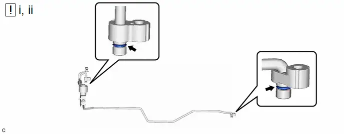
(1) Sufficiently apply compressor oil to 2 new O-rings and the fitting surface of the No. 1 traction battery cooler tube.
Compressor Oil:
ND-OIL 11 or equivalent
NOTICE:
Do not use any compressor oil other than ND-OIL 11 or equivalent. If any compressor oil other than ND-OIL 11 or equivalent is used, compressor motor insulation performance may decrease, resulting in leakage of electric power.
(2) Install the 2 O-rings to the No. 1 traction battery cooler tube.
NOTICE:
Keep the O-ring and O-ring fitting surface free of foreign matter.
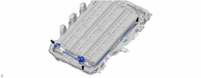
Torque:
7,5 N·m {76 kgf·cm, 66 in·lbf}
2. INSTALL NO. 2 TRACTION BATTERY COOLER TUBE
 |
CAUTION: Be sure to wear insulated gloves and protective goggles. NOTICE: Do not apply excessive force to the pipe. |
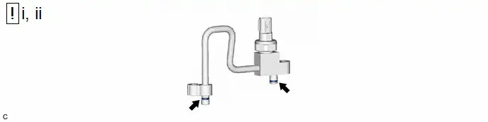
(1) Sufficiently apply compressor oil to a new O-ring and the fitting surface of the No. 2 traction battery cooler tube.
Compressor Oil:
ND-OIL 11 or equivalent
NOTICE:
Do not use any compressor oil other than ND-OIL 11 or equivalent. If any compressor oil other than ND-OIL 11 or equivalent is used, compressor motor insulation performance may decrease, resulting in leakage of electric power.
(2) Install the 2 O-rings to the No. 2 traction battery cooler tube.
NOTICE:
Keep the O-ring and O-ring fitting surface free of foreign matter.

Torque:
7,5 N·m {76 kgf·cm, 66 in·lbf}
3. INSPECT INSPECT FOR REFRIGERANT LEAK
Click here 
4. INSTALL NO. 10 TRACTION BATTERY BRACKET
 |
CAUTION: Be sure to wear insulated gloves and protective goggles. |
Torque:
7,5 N·m {76 kgf·cm, 66 in·lbf}
5. INSTALL NO. 14 TRACTION BATTERY BRACKET
 |
CAUTION: Be sure to wear insulated gloves and protective goggles. |
Torque:
7,5 N·m {76 kgf·cm, 66 in·lbf}
6. INSTALL BATTERY ECU ASSEMBLY
Click here 
7. INSTALL BATTERY VOLTAGE SENSOR
Click here 
8. INSTALL NO. 1 TRACTION BATTERY HEATER RELAY
Click here 
9. INSTALL NO. 1 TRACTION BATTERY DEVICE BOX ASSEMBLY
Click here 
Airtight Inspection
AIRTIGHT INSPECTION
PROCEDURE
1. INSPECT INSPECT FOR REFRIGERANT LEAK
(a) Sufficiently apply compressor oil to 2 SST O-rings. SST: 09893-10060 SST: 09893-10070 Compressor Oil: ND-OIL 11 or equivalent NOTICE: Do not use any compressor oil other than ND-OIL 11 or equivalent. If any compressor oil other than ND-OIL 11 or equivalent is used, compressor motor insulation performance may decrease, resulting in leakage of electric power. |
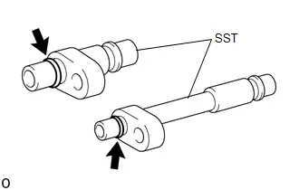 |
(b) Install the SST with the 2 bolts. Torque: 9,8 N·m {100 kgf·cm, 7 ft·lbf} |
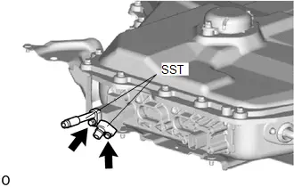 |
(c) Connect a refrigerant recovery unit to the SST. NOTICE: Use the refrigerant recovery unit in accordance with the manufacturer's instruction manual. |
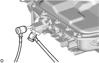 |
(d) Perform vacuum drawing.
OK:
Can maintain the vacuum state for more than 5 minutes.