Front Lower Suspension Arm (for M20a-fxs)
- Removal
- Installation
Removal
REMOVAL
The necessary procedures (adjustment, calibration, initialization, or registration) that must be performed after parts are removed and installed, or replaced during front lower No. 1 suspension arm sub-assembly removal/installation are shown below.
Necessary Procedures After Parts Removed/Installed/ReplacedReplaced Part or Performed Procedure | Necessary Procedure | Effect/Inoperative Function when Necessary Procedure not Performed | Link |
|---|---|---|---|
| *1: Also necessary after performing a tire rotation. *2: It is not necessary to perform this procedure if the tire pressure warning valve and transmitters are installed to the same location. *3: The Toyota Prius vehicle height changes because of tire replacement. |
|||
Front wheel alignment adjustment |
Perform "Calibration" |
|
 |
Suspension parts |
Rear television camera assembly optical axis (Back camera position setting) |
Parking Assist Monitor System |
 |
Parking assist ECU initialization |
Panoramic View Monitor System |
 |
|
Advanced Park |
 |
||
Tires |
|
Tire Pressure Warning System |
Refer to Procedures Necessary When Replacing Parts (for Tire Pressure Warning System)   |
Rear television camera assembly optical axis (Back camera position setting) |
Parking Assist Monitor System |
 |
|
Parking assist ECU initialization*3 |
Panoramic View Monitor System |
 |
|
Advanced Park |
 |
||
HINT:
- Use the same procedure for the RH side and LH side.
- The following procedure is for the LH side.
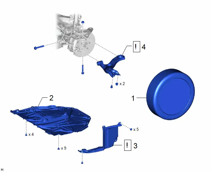
Procedure | Part Name Code |  |  |  |
|
|---|---|---|---|---|---|
1 |
FRONT WHEEL |
- |
- |
- |
- |
2 |
NO. 1 ENGINE UNDER COVER ASSEMBLY |
51410 |
- |
- |
- |
3 |
REAR ENGINE UNDER COVER LH |
51444A |
 |
- |
- |
4 |
FRONT LOWER NO. 1 SUSPENSION ARM SUB-ASSEMBLY |
48069 |
 |
- |
- |
PROCEDURE
1. REMOVE FRONT WHEEL
Click here 
2. REMOVE NO. 1 ENGINE UNDER COVER ASSEMBLY
Click here 

3. REMOVE REAR ENGINE UNDER COVER LH
 |
|


4. REMOVE FRONT LOWER NO. 1 SUSPENSION ARM SUB-ASSEMBLY
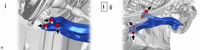
(1) Remove the bolt and 2 nuts and separate the front lower No. 1 suspension arm sub-assembly from the front lower ball joint assembly.
(2) Remove the 2 bolts, nut and front lower No. 1 suspension arm sub-assembly from the front suspension crossmember sub-assembly.
NOTICE:
Because the nut has its own stopper, do not turn the nut. Loosen the bolt with the nut secured.
Installation
INSTALLATION
HINT:
- Use the same procedure for the RH side and LH side.
- The following procedure is for the LH side.
- This procedure is for the LH side. If it is not specified, perform the same procedure as for the LH side.
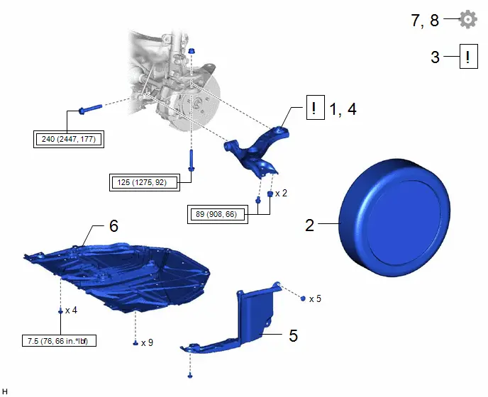
Procedure | Part Name Code |  |  |  |
|
|---|---|---|---|---|---|
1 |
TEMPORARILY INSTALL FRONT LOWER NO. 1 SUSPENSION ARM SUB-ASSEMBLY |
48069 |
 |
- |
- |
2 |
FRONT WHEEL |
- |
- |
- |
- |
3 |
STABILIZE SUSPENSION |
- |
 |
- |
- |
4 |
FULLY TIGHTEN FRONT LOWER NO. 1 SUSPENSION ARM SUB-ASSEMBLY |
48069 |
 |
- |
- |
5 |
REAR ENGINE UNDER COVER LH |
51444A |
- |
- |
- |
6 |
NO. 1 ENGINE UNDER COVER ASSEMBLY |
51410 |
- |
- |
- |
7 |
INSPECT AND ADJUST FRONT WHEEL ALIGNMENT |
- |
- |
- |
 |
8 |
PERFORM INITIALIZATION |
- |
- |
- |
 |
 |
Tightening torque for "Major areas involving basic Toyota Prius vehicle performance such as moving/turning/stopping" : N*m (kgf*cm, ft.*lbf) |
 |
N*m (kgf*cm, ft.*lbf): Specified torque |
PROCEDURE
1. TEMPORARILY INSTALL FRONT LOWER NO. 1 SUSPENSION ARM SUB-ASSEMBLY
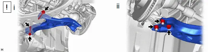
(1) Temporarily install the front lower No. 1 suspension arm sub-assembly to the front suspension crossmember sub-assembly with the 2 bolts and nut.
NOTICE:
Because the nut has its own stopper, do not turn the nut. Tighten the bolt with the nut secured.
(2) Connect the front lower No. 1 suspension arm sub-assembly to the front lower ball joint assembly with the bolt and 2 nuts.
Torque:
89 N·m {908 kgf·cm, 66 ft·lbf}
2. INSTALL FRONT WHEEL
Click here 
3. STABILIZE SUSPENSION
 |
Click here |


4. FULLY TIGHTEN FRONT LOWER NO. 1 SUSPENSION ARM SUB-ASSEMBLY
 |
for LH Side: Click here for RH Side: Click here |


5. INSTALL REAR ENGINE UNDER COVER LH
6. INSTALL NO. 1 ENGINE UNDER COVER ASSEMBLY
Click here 

7. INSPECT AND ADJUST FRONT WHEEL ALIGNMENT
Click here 

8. PERFORM INITIALIZATION
Parking Assist Monitor System |
 |
Panoramic View Monitor System |
 |
Advanced Park |
 |