Digital Key Receiver (for Rear Door)
- Removal
- Installation
Removal
REMOVAL
The necessary procedures (adjustment, calibration, initialization or registration) that must be performed after parts are removed and installed, or replaced during ble door digital key receiver assembly (for rear door) removal/installation are shown below.
Necessary Procedure After Parts Removed/Installed/ReplacedReplaced Part or Performed Procedure | Necessary Procedure | Effect/Inoperative Function when Necessary Procedure not Performed | Link |
|---|---|---|---|
BLE door digital key receiver assembly (for rear door) |
Code registration |
|
 |
NOTICE:
After turning the ignition switch off, waiting time may be required before disconnecting the cable from the negative (-) auxiliary battery terminal.
Click here 
HINT:
When the cable is disconnected/reconnected to the auxiliary battery terminal, systems temporarily stop operating. However, each system has a function that completes learning the first time the system is used.
- Items for which learning is completed by driving the Toyota Prius vehicle
Effect/Inoperative Function When Necessary Procedures are not Performed
Necessary Procedures
Link
Front Camera System
Drive the Toyota Prius vehicle straight ahead at 35 km/h or more for 5 second or more.

- Items for which learning is completed by operating the vehicle normally
Effect/Inoperative Function When Necessary Procedures are not Performed
Necessary Procedures
Link
*1: w/o Power Back Door System *2: w/ Power Back Door System
Power Door Lock Control System*1
- Back door opener
Perform door unlock operation with door control switch or electrical key transmitter sub-assembly switch.

Power Back Door System*2
Reset back door close position

Air Conditioning System
for HEV Model: - After the ignition switch is turned to ON, the servo motor standard position is recognized.
- After the ignition switch is turned to ON, the servo motor and expansion valve standard position is recognized.
-
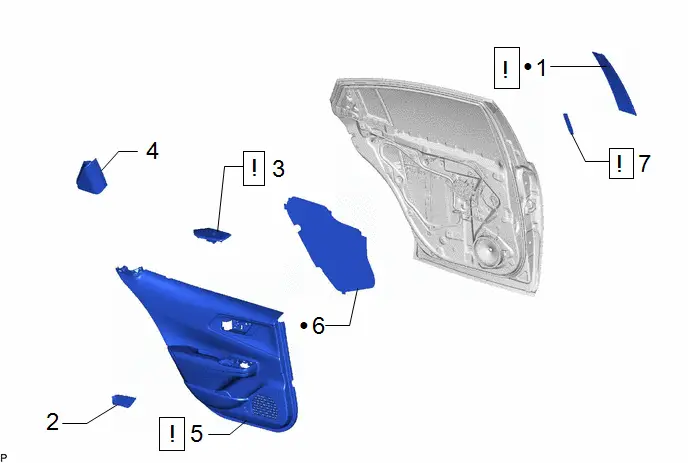
Procedure | Part Name Code |  |  |  |
|
|---|---|---|---|---|---|
1 |
REAR DOOR WINDOW FRAME FRONT MOULDING |
75762A |
 |
- |
- |
2 |
REAR DOOR TRIM UPPER COVER |
67782D |
- |
- |
- |
3 |
REAR POWER WINDOW REGULATOR SWITCH ASSEMBLY WITH REAR DOOR UPPER ARMREST BASE PANEL |
- |
 |
- |
- |
4 |
REAR DOOR REAR FRAME BRACKET |
67498 |
- |
- |
- |
5 |
REAR DOOR TRIM BOARD SUB-ASSEMBLY |
67604 |
 |
- |
- |
6 |
REAR DOOR SERVICE HOLE COVER |
67842E |
- |
- |
- |
7 |
BLE DOOR DIGITAL KEY RECEIVER ASSEMBLY (for Rear Door) |
890D0 |
 |
- |
- |
● |
Non-reusable part |
- |
- |
PROCEDURE
1. REMOVE REAR DOOR WINDOW FRAME FRONT MOULDING
 |
Click here |

2. REMOVE REAR DOOR TRIM UPPER COVER
Click here 
3. REMOVE REAR POWER WINDOW REGULATOR SWITCH ASSEMBLY WITH REAR DOOR UPPER ARMREST BASE PANEL
 |
Click here |

4. REMOVE REAR DOOR REAR FRAME BRACKET
Click here 
5. REMOVE REAR DOOR TRIM BOARD SUB-ASSEMBLY
 |
Click here |

6. REMOVE REAR DOOR SERVICE HOLE COVER
Click here 
7. REMOVE BLE DOOR DIGITAL KEY RECEIVER ASSEMBLY (for Rear Door)
 |
NOTICE: Be careful when removing the digital key receiver. If the digital key receiver is dropped, replace it with a new one. |
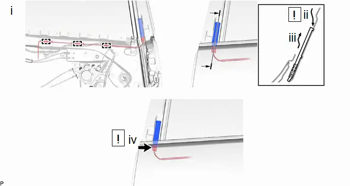
(1) Disengage the 3 clamps.
(2) Peel off the ble door digital key receiver assembly (for rear door) using a moulding remover E or equivalent.
(3) Pull up the ble door digital key receiver assembly (for rear door).
(4) Disconnect the connector to remove the ble door digital key receiver assembly (for rear door).
NOTICE:
Prevent the detached wire harness from falling into the door panel.
Installation
INSTALLATION
HINT:
- Use the same procedure for the LH side and RH side.
- The following procedure is for the LH side.
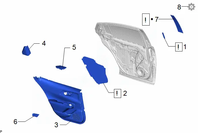
Procedure | Part Name Code |  |  |  |
|
|---|---|---|---|---|---|
1 |
BLE DOOR DIGITAL KEY RECEIVER ASSEMBLY (for Rear Door) |
890D0 |
 |
- |
- |
2 |
REAR DOOR SERVICE HOLE COVER |
67842E |
 |
- |
- |
3 |
REAR DOOR TRIM BOARD SUB-ASSEMBLY |
67604 |
- |
- |
- |
4 |
REAR DOOR REAR FRAME BRACKET |
67498 |
- |
- |
- |
5 |
REAR POWER WINDOW REGULATOR SWITCH ASSEMBLY WITH REAR DOOR UPPER ARMREST BASE PANEL |
- |
- |
- |
- |
6 |
REAR DOOR TRIM UPPER COVER |
67782D |
- |
- |
- |
7 |
REAR DOOR WINDOW FRAME FRONT MOULDING |
75762A |
 |
- |
- |
8 |
REGISTRATION DIGITAL KEY ECU |
- |
- |
- |
 |
● |
Non-reusable part |
- |
- |
PROCEDURE
1. INSTALL BLE DOOR DIGITAL KEY RECEIVER ASSEMBLY (for Rear Door)
 |
NOTICE: Be careful when installing the digital key receiver. If the digital key receiver is dropped, replace it with a new one. |
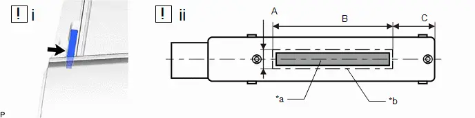
*a |
Double-sided Tape: 50 mm X 5.6 mm (1.97 in. X 0.22 in.) |
*b |
Double-sided Tape Application Area |
Standard Measurement:
Area | Measurement | Area | Measurement |
|---|---|---|---|
A |
8.6 mm (0.34 in.) |
B |
53 mm (2.09 in.) |
C |
18.5 mm (0.73 in.) |
- |
- |
(1) Clean the rear door surface.
1. Using a heat light, heat the double-sided tape remaining on the rear door surface and the ble door digital key receiver assembly (for rear door).
Heating TemperatureArea | Temperature | Area | Temperature |
|---|---|---|---|
Rear Door |
40 to 60 °C |
BLE Door Digital Key Receiver Assembly (for rear door) |
20 to 30 °C |
CAUTION:
- Do not touch the heat light and heated parts, touching the heat light may result in burns.
- Touching heated parts for a long time may result in burns.
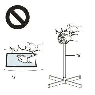
*a |
Heated Part |
*b |
Heat Light |
NOTICE:
Do not heat the front fender panel excessively.
2. Remove any remaining double-sided tape from the rear door surface and the ble door digital key receiver assembly (for rear door).
3. Wipe off any tape adhesive residue with cleaner.
(2) The double-side tape shall be attached in specified area regardless of position and orientation.
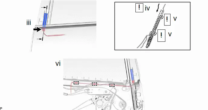
(3) Connect the connector to the ble door digital key receiver assembly (for rear door).
(4) Slide the ble door digital key receiver assembly (for rear door) while pressing the ble door digital key receiver assembly (for rear door) against the glass channel.
(5) When ANT falls into the recess peeling off the release paper. After that, fix it firmly with your finger pad.
(6) Engage the 3 clamps.
2. INSTALL REAR DOOR SERVICE HOLE COVER
 |
Click here |

3. INSTALL REAR DOOR TRIM BOARD SUB-ASSEMBLY
4. INSTALL REAR DOOR REAR FRAME BRACKET
5. INSTALL REAR POWER WINDOW REGULATOR SWITCH ASSEMBLY WITH REAR DOOR UPPER ARMREST BASE PANEL
6. INSTALL REAR DOOR TRIM UPPER COVER
7. INSTALL REAR DOOR WINDOW FRAME FRONT MOULDING
 |
Click here |

8. REGISTRATION DIGITAL KEY SYSTEM
Click here 