Engine Assembly
- Removal
- Installation
Removal
REMOVAL
The necessary procedures (adjustment, calibration, initialization or registration) that must be performed after parts are removed and installed, or replaced during engine assembly removal/installation are shown below.
Necessary Procedures After Parts Removed/Installed/ReplacedReplaced Part or Performed Procedure | Necessary Procedure | Effect/Inoperative Function when Necessary Procedure not Performed | Link |
|---|---|---|---|
| *: Even when not replacing the part, it is necessary to perform the specified necessary procedures after installation. *1: Also necessary after performing a tire rotation. *2: It is not necessary to perform this procedure if the tire pressure warning valve and transmitters are installed to the same location. |
|||
Replacement of ECM |
Update ECU security key |
Toyota Prius Vehicle Control History (RoB) are stored |
 |
ECU configuration |
- |
 |
|
Perform Toyota Prius Vehicle Identification Number (VIN) registration |
DTC is output |
 |
|
|
Inspection after repair |
|
 |
Replacement of inverter with converter assembly |
ECU configuration |
- |
 |
Resolver learning |
|
 |
|
Replacement of hybrid vehicle transaxle assembly |
|
|
 |
Suspension parts |
Rear television camera assembly optical axis (Back camera position setting) |
Parking Assist Monitor System |
 |
Parking assist ECU initialization |
Panoramic View Monitor System |
 |
|
Advanced Park |
 |
||
Tires |
|
Tire Pressure Warning System |
Refer to Procedures Necessary When Replacing Parts (for Tire Pressure Warning System) table below |
Rear television camera assembly optical axis (Back camera position setting) |
Parking Assist Monitor System |
 |
|
Parking assist ECU initialization |
Panoramic View Monitor System |
 |
|
Advanced Park |
 |
||
Replacement of front bumper assembly* |
Front television camera view adjustment |
Panoramic View Monitor System |
 |
Advanced Park |
 |
||
CAUTION:
- The engine assembly with transaxle is very heavy. Be sure to follow the procedure described in the repair manual, or the engine lifter may suddenly drop or the engine assembly with transaxle may fall off the engine lifter.
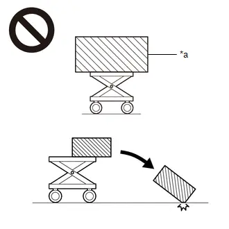
*a
An Object Exceeding Weight Limit of Engine Lifter
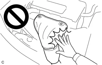
- To prevent burns, do not touch the engine, exhaust manifold or other high temperature components while the engine is hot.
- Orange wire harnesses and connectors indicate high-voltage circuits. To prevent electric shock, always follow the procedure described in the repair manual.
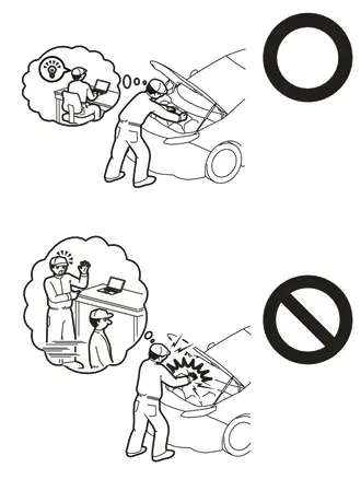
Click here

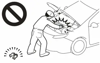
- To prevent electric shock, wear insulated gloves when working on wire harnesses and components of the high voltage system.
NOTICE:
When disconnecting a wire harness of any component connected to the supply power of the integrated capacitor (integration control supply) or when removing the integrated capacitor (integration control supply), make sure to wait 5 minutes or more after turning the ignition switch off for self-diagnosis to complete and the voltage of the integrated capacitor (integration control supply) to discharge.
HINT:
When the cable is disconnected / reconnected to the auxiliary battery terminal, systems temporarily stop operating. However, each system has a function that completes learning the first time the system is used.
- Learning completes when Toyota Prius vehicle is driven
Effect/Inoperative Function When Necessary Procedures are not Performed
Necessary Procedures
Link
Front Camera System
Drive the Toyota Prius vehicle straight ahead at 35 km/h or more for 5 seconds or more.

- Learning completes when vehicle is operated normally
Effect/Inoperative Function When Necessary Procedures are not Performed
Necessary Procedures
Link
*1: w/o Power Back Door System *2: w/ Power Back Door System
Power Door Lock Control System*1
- Back door opener
Perform door unlock operation with door control switch or electrical key transmitter sub-assembly switch.

Power Back Door System*2
Reset back door close position

Air Conditioning System
After the ignition switch is turned to ON, the servo motor standard position is recognized.
-
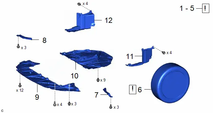
Procedure | Part Name Code |  |  |  |
|
|---|---|---|---|---|---|
1 |
PRECAUTION |
- |
 |
- |
- |
2 |
RECOVER REFRIGERANT FROM REFRIGERATION SYSTEM |
- |
 |
- |
- |
3 |
DISCHARGE FUEL SYSTEM PRESSURE |
- |
 |
- |
- |
4 |
ALIGN FRONT WHEELS FACING STRAIGHT AHEAD |
- |
 |
- |
- |
5 |
SECURE STEERING WHEEL |
- |
 |
- |
- |
6 |
FRONT WHEELS |
- |
 |
- |
- |
7 |
FRONT WHEEL OPENING EXTENSION PAD LH |
53852B |
- |
- |
- |
8 |
FRONT WHEEL OPENING EXTENSION PAD RH |
53851D |
- |
- |
- |
9 |
CENTER ENGINE UNDER COVER |
51451A |
- |
- |
- |
10 |
NO. 1 ENGINE UNDER COVER ASSEMBLY |
51410 |
- |
- |
- |
11 |
REAR ENGINE UNDER COVER LH |
51444A |
- |
- |
- |
12 |
REAR ENGINE UNDER COVER RH |
51443C |
- |
- |
- |
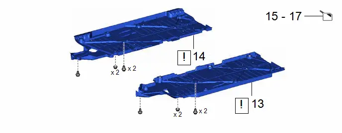
Procedure | Part Name Code |  |  |  |
|
|---|---|---|---|---|---|
13 |
FRONT FLOOR COVER LH |
58166A |
 |
- |
- |
14 |
FRONT FLOOR COVER RH |
58165C |
 |
- |
- |
15 |
DRAIN ENGINE OIL |
- |
- |
 |
- |
16 |
DRAIN ENGINE COOLANT (for Engine) |
- |
- |
 |
- |
17 |
DRAIN HYBRID TRANSAXLE FLUID |
- |
- |
 |
- |
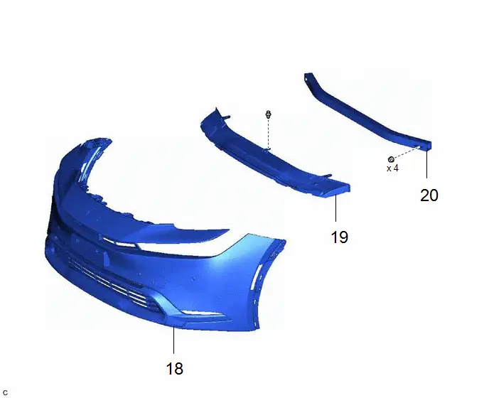
Procedure | Part Name Code |  |  |  |
|
|---|---|---|---|---|---|
18 |
FRONT BUMPER ASSEMBLY |
- |
- |
- |
- |
19 |
FRONT BUMPER LOWER ABSORBER |
52618 |
- |
- |
- |
20 |
NO. 2 FRONT BUMPER REINFORCEMENT |
52132A |
- |
- |
- |
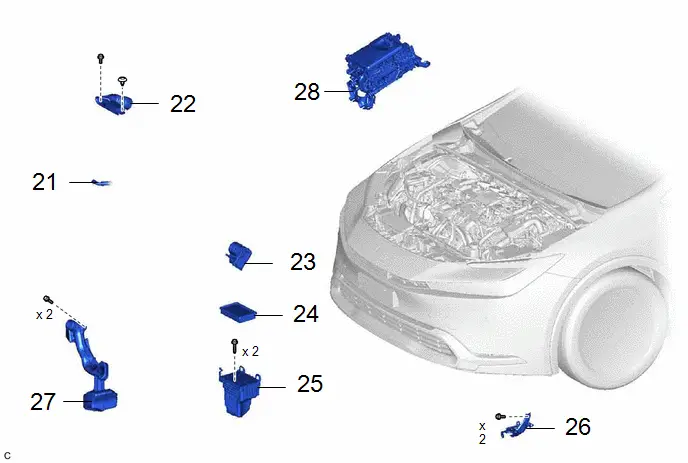
Procedure | Part Name Code |  |  |  |
|
|---|---|---|---|---|---|
21 |
NO. 8 WATER BY-PASS HOSE |
16296 |
- |
- |
- |
22 |
INLET NO. 2 AIR CLEANER |
17752 |
- |
- |
- |
23 |
THROTTLE BODY ASSEMBLY |
22210 |
- |
- |
- |
24 |
AIR CLEANER FILTER ELEMENT SUB-ASSEMBLY |
17801 |
- |
- |
- |
25 |
AIR CLEANER CASE SUB-ASSEMBLY |
17701 |
- |
- |
- |
26 |
AIR CLEANER BRACKET |
17771A |
- |
- |
- |
27 |
INLET NO. 1 AIR CLEANER |
17751 |
- |
- |
- |
28 |
INVERTER WITH CONVERTER ASSEMBLY |
G9200 |
- |
- |
- |
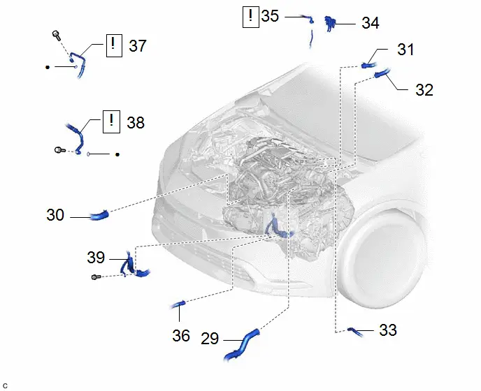
Procedure | Part Name Code |  |  |  |
|
|---|---|---|---|---|---|
29 |
NO. 1 RADIATOR HOSE |
16571C |
- |
- |
- |
30 |
NO. 2 RADIATOR HOSE |
16572D |
- |
- |
- |
31 |
INLET HEATER WATER HOSE |
87245 |
- |
- |
- |
32 |
OUTLET HEATER WATER HOSE |
87246 |
- |
- |
- |
33 |
NO. 1 FUEL VAPOR FEED HOSE |
23826 |
- |
- |
- |
34 |
EFI FUEL PIPE CLAMP |
23842A |
- |
- |
- |
35 |
FUEL TUBE SUB-ASSEMBLY |
23901 |
 |
- |
- |
36 |
NO. 2 INVERTER COOLING OUTLET HOSE |
G922D |
- |
- |
- |
37 |
DISCHARGE HOSE SUB-ASSEMBLY |
88703 |
 |
- |
- |
38 |
SUCTION HOSE SUB-ASSEMBLY |
88704 |
 |
- |
- |
39 |
NO. 7 ENGINE WIRE |
82127D |
- |
- |
- |
● |
Non-reusable part |
- |
- |
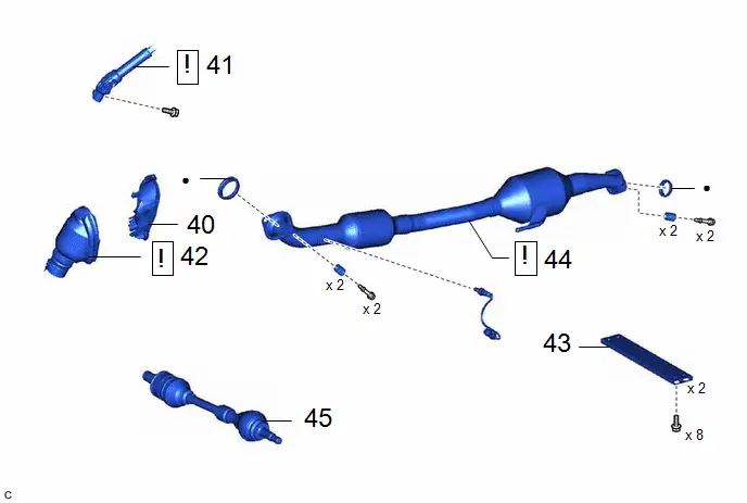
Procedure | Part Name Code |  |  |  |
|
|---|---|---|---|---|---|
40 |
COLUMN HOLE COVER SILENCER SHEET |
45259A |
- |
- |
- |
41 |
NO. 2 STEERING INTERMEDIATE SHAFT ASSEMBLY |
45260 |
 |
- |
- |
42 |
NO. 1 STEERING COLUMN HOLE COVER SUB-ASSEMBLY |
45025D |
 |
- |
- |
43 |
FRONT FLOOR CENTER BRACE |
57533B |
- |
- |
- |
44 |
FRONT EXHAUST PIPE ASSEMBLY |
17410 |
 |
- |
- |
45 |
FRONT DRIVE SHAFT ASSEMBLY |
- |
- |
- |
- |
● |
Non-reusable part |
- |
- |
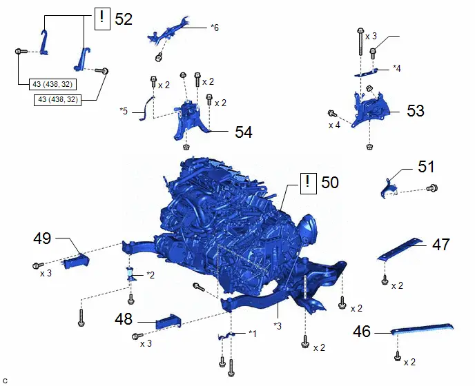
Procedure | Part Name Code |  |  |  |
|
|---|---|---|---|---|---|
46 |
NO. 2 CROSSMEMBER GUSSET LH |
51322 |
- |
- |
- |
47 |
NO. 2 CROSSMEMBER GUSSET RH |
51321 |
- |
- |
- |
48 |
FRONT BUMPER EXTENSION SUB-ASSEMBLY LH |
52103A |
- |
- |
- |
49 |
FRONT BUMPER EXTENSION SUB-ASSEMBLY RH |
52102B |
- |
- |
- |
50 |
ENGINE ASSEMBLY WITH TRANSAXLE |
- |
 |
- |
- |
51 |
WIRE HARNESS CLAMP BRACKET |
- |
- |
- |
- |
52 |
INSTALL ENGINE HANGERS |
- |
 |
- |
- |
53 |
ENGINE MOUNTING INSULATOR LH |
12372A |
- |
- |
- |
54 |
ENGINE MOUNTING INSULATOR SUB-ASSEMBLY RH |
12305 |
- |
- |
- |
*1 |
CENTER RADIATOR SUPPORT LH |
*2 |
CENTER RADIATOR SUPPORT RH |
*3 |
FRONT SUSPENSION CROSSMEMBER SUB-ASSEMBLY |
*4 |
NO. 2 ENGINE MOUNTING STAY LH |
*5 |
NO. 2 EARTH WIRE |
*6 |
AIR CONDITIONER TUBE AND ACCESSORY ASSEMBLY |
 |
N*m (kgf*cm, ft.*lbf): Specified torque |
★ |
Precoated part |
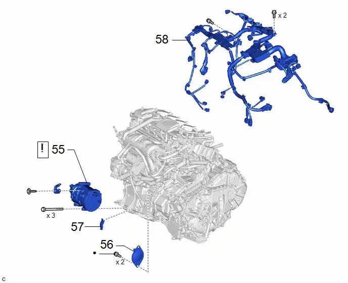
Procedure | Part Name Code |  |  |  |
|
|---|---|---|---|---|---|
55 |
COMPRESSOR WITH MOTOR ASSEMBLY |
88370 |
 |
- |
- |
56 |
STARTER HOLE INSULATOR |
28193 |
- |
- |
- |
57 |
FLYWHEEL HOUSING SIDE COVER |
11363A |
- |
- |
- |
58 |
ENGINE WIRE |
82121 |
- |
- |
- |
● |
Non-reusable part |
- |
- |
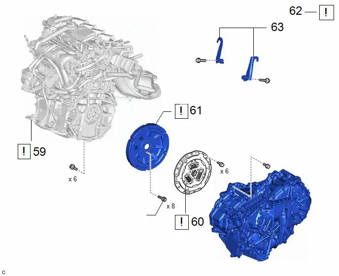
Procedure | Part Name Code |  |  |  |
|
|---|---|---|---|---|---|
59 |
ENGINE ASSEMBLY |
- |
 |
- |
- |
60 |
TRANSMISSION INPUT DAMPER ASSEMBLY |
31270 |
 |
- |
- |
61 |
FLYWHEEL SUB-ASSEMBLY |
13405 |
 |
- |
- |
62 |
INSTALL ENGINE ASSEMBLY TO ENGINE STAND |
- |
 |
- |
- |
63 |
REMOVE ENGINE HANGERS |
- |
- |
- |
- |
★ |
Precoated part |
- |
- |
PROCEDURE
1. PRECAUTION
Click here 

2. RECOVER REFRIGERANT FROM REFRIGERATION SYSTEM
- for HFC-134a (R134a):
Click here

- for HFO-1234yf (R1234yf):
Click here


3. DISCHARGE FUEL SYSTEM PRESSURE
Click here 
4. ALIGN FRONT WHEELS FACING STRAIGHT AHEAD
5. SECURE STEERING WHEEL
 |
Click here |

6. REMOVE FRONT WHEELS
 |
Click here |

7. REMOVE FRONT WHEEL OPENING EXTENSION PAD LH

8. REMOVE FRONT WHEEL OPENING EXTENSION PAD RH

9. REMOVE CENTER ENGINE UNDER COVER
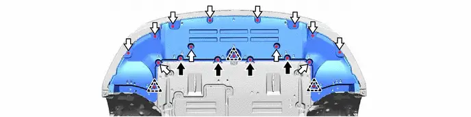
 |
Bolt |
 |
Screw |
10. REMOVE NO. 1 ENGINE UNDER COVER ASSEMBLY

11. REMOVE REAR ENGINE UNDER COVER LH

12. REMOVE REAR ENGINE UNDER COVER RH

13. REMOVE FRONT FLOOR COVER LH
 |
Click here |

14. REMOVE FRONT FLOOR COVER RH
 |
Click here |

15. DRAIN ENGINE OIL
Click here 
16. DRAIN ENGINE COOLANT (for Engine)
Click here 
17. DRAIN HYBRID TRANSAXLE FLUID
Click here 

18. REMOVE FRONT BUMPER ASSEMBLY
Click here 
19. REMOVE FRONT BUMPER LOWER ABSORBER
Click here 
20. REMOVE NO. 2 FRONT BUMPER REINFORCEMENT
Click here 
21. DISCONNECT NO. 8 WATER BY-PASS HOSE

22. REMOVE INLET NO. 2 AIR CLEANER
Click here 
23. REMOVE THROTTLE BODY ASSEMBLY
Click here 
24. REMOVE AIR CLEANER FILTER ELEMENT SUB-ASSEMBLY
Click here 
25. REMOVE AIR CLEANER CASE SUB-ASSEMBLY
Click here 
26. REMOVE AIR CLEANER BRACKET
Click here 
27. REMOVE INLET NO. 1 AIR CLEANER
Click here 
28. REMOVE INVERTER WITH CONVERTER ASSEMBLY
Click here 
29. DISCONNECT NO. 1 RADIATOR HOSE

30. DISCONNECT NO. 2 RADIATOR HOSE

31. DISCONNECT INLET HEATER WATER HOSE

32. DISCONNECT OUTLET HEATER WATER HOSE

33. DISCONNECT NO. 1 FUEL VAPOR FEED HOSE

34. REMOVE EFI FUEL PIPE CLAMP
Click here 
35. DISCONNECT FUEL TUBE SUB-ASSEMBLY
 |
Click here |

36. DISCONNECT NO. 2 INVERTER COOLING OUTLET HOSE

37. DISCONNECT DISCHARGE HOSE SUB-ASSEMBLY
 |
Click here |


38. DISCONNECT SUCTION HOSE SUB-ASSEMBLY
 |
Click here |


39. DISCONNECT NO. 7 ENGINE WIRE

40. REMOVE COLUMN HOLE COVER SILENCER SHEET
Click here 

41. SEPARATE NO. 2 STEERING INTERMEDIATE SHAFT ASSEMBLY
 |
Click here |


42. SEPARATE NO. 1 STEERING COLUMN HOLE COVER SUB-ASSEMBLY
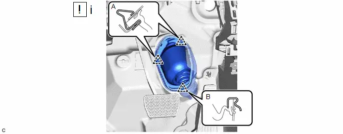
(1) Separate the clip (A), disengage the clip (B) from the Toyota Prius vehicle body and separate the No. 1 steering column hole cover sub-assembly.
NOTICE:
Do not damage the clips (A) or (B).
43. REMOVE FRONT FLOOR CENTER BRACE
Click here 
44. REMOVE FRONT EXHAUST PIPE ASSEMBLY
 |
Click here |

45. REMOVE FRONT DRIVE SHAFT ASSEMBLY
Click here 
46. REMOVE NO. 2 CROSSMEMBER GUSSET LH

47. REMOVE NO. 2 CROSSMEMBER GUSSET RH

48. REMOVE FRONT BUMPER EXTENSION SUB-ASSEMBLY LH

49. REMOVE FRONT BUMPER EXTENSION SUB-ASSEMBLY RH

50. REMOVE ENGINE ASSEMBLY WITH TRANSAXLE
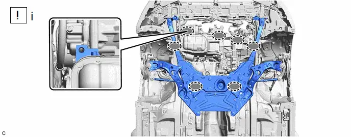
 |
Attachment Installation Position |
- |
- |
(1) Set the engine assembly with transaxle on an engine lifter.
NOTICE:
- Using height adjustment attachments and plate lift attachments, keep the engine assembly with transaxle and front suspension crossmember sub-assembly level.
- Do not perform any procedures while the engine assembly is suspended because doing so may cause the engine assembly to drop, resulting in injury. However, the engine assembly needs to be suspended when it is installed to or removed from an engine stand.
- To prevent the engine assembly from unexpectedly moving, securely support the engine assembly until it is secured to an engine stand.
- To prevent the oil pan sub-assembly from deforming, do not place any attachments under the oil pan sub-assembly of the engine assembly with transaxle.
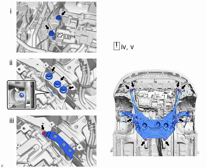
*1 |
Center Radiator Support LH |
*2 |
Center Radiator Support RH |
 |
Bolt |
 |
Nut |
(1) Remove the 2 bolts and nut and separate the engine mounting insulator sub-assembly RH from the engine mounting bracket RH.
(2) Remove the 3 bolts and nut and separate the engine mounting insulator LH from the hybrid Toyota Prius vehicle transaxle assembly.
(3) Remove the bolt and No. 2 engine mounting stay LH.
(4) Remove the 8 bolts to separate the front suspension crossmember sub-assembly, center radiator support LH and center radiator support RH from the vehicle.
(5) Operate the engine lifter and remove the engine assembly with transaxle from the Toyota Prius vehicle.
NOTICE:
- Make sure that the engine assembly with transaxle is clear of all wiring and hoses.
- While lowering the engine assembly with transaxle from the vehicle, do not allow it to contact the vehicle.
51. REMOVE WIRE HARNESS CLAMP BRACKET

52. INSTALL ENGINE HANGERS
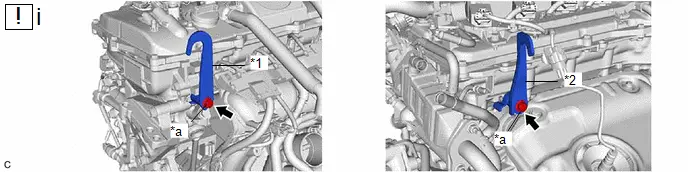
*1 |
No. 1 Engine Hanger |
*2 |
No. 2 Engine Hanger |
*a |
Bolt |
- |
- |
(1) Install the No. 1 engine hanger and No. 2 engine hanger with the 2 bolts.
Torque:
43 N·m {438 kgf·cm, 32 ft·lbf}
No. 1 Engine Hanger |
12281-37070 |
No. 2 Engine Hanger |
12282-37060 |
Bolt |
91552-81050 |

(1) Using an engine sling device and engine lifter, secure the engine assembly with transaxle.
NOTICE:
- Adjust the angle of the sling device carefully to prevent damage or deformation to the engine hangers or engine assembly.
- Do not perform any procedures while the engine assembly is suspended because doing so may cause the engine assembly to drop, resulting in injury. However, the engine assembly needs to be suspended when it is installed to or removed from an engine stand.
53. REMOVE ENGINE MOUNTING INSULATOR LH
HINT:
Perform this procedure only when replacement of the engine mounting insulator LH is necessary.

54. REMOVE ENGINE MOUNTING INSULATOR SUB-ASSEMBLY RH
HINT:
Perform this procedure only when replacement of the engine mounting insulator sub-assembly RH is necessary.
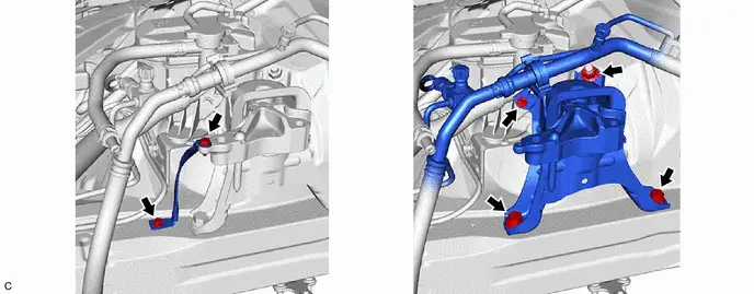
55. REMOVE COMPRESSOR WITH MOTOR ASSEMBLY
 |
Click here |


56. REMOVE STARTER HOLE INSULATOR
Click here 
57. REMOVE FLYWHEEL HOUSING SIDE COVER
Click here 
58. REMOVE ENGINE WIRE
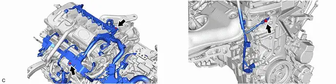
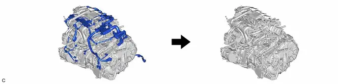
HINT:
The illustrations are representative examples, and details may differ.
59. REMOVE ENGINE ASSEMBLY
 |
Click here |

60. REMOVE TRANSMISSION INPUT DAMPER ASSEMBLY
 |
Click here |

61. REMOVE FLYWHEEL SUB-ASSEMBLY
 |
Click here |

62. INSTALL ENGINE ASSEMBLY TO ENGINE STAND

63. REMOVE ENGINE HANGERS
Installation
INSTALLATION
CAUTION:
The engine assembly with transaxle is very heavy. Be sure to follow the procedure described in the repair manual, or the engine lifter may suddenly drop.
HINT:
Perform "Inspection After Repair" after replacing the engine assembly.
Click here 
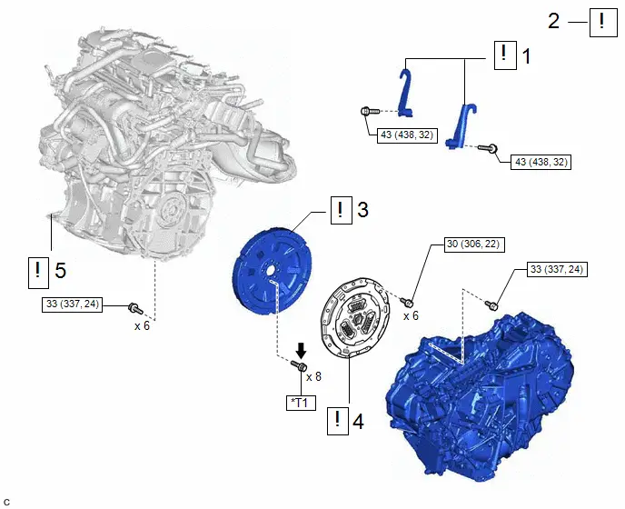
Procedure | Part Name Code |  |  |  |
|
|---|---|---|---|---|---|
1 |
INSTALL ENGINE HANGERS |
- |
 |
- |
- |
2 |
REMOVE ENGINE ASSEMBLY FROM ENGINE STAND |
- |
 |
- |
- |
3 |
FLYWHEEL SUB-ASSEMBLY |
13405 |
 |
- |
- |
4 |
TRANSMISSION INPUT DAMPER ASSEMBLY |
31270 |
 |
- |
- |
5 |
ENGINE ASSEMBLY |
- |
 |
- |
- |
 |
N*m (kgf*cm, ft.*lbf): Specified torque |
 |
Adhesive 1324 |
★ |
Precoated part |
*T1 |
1st: 49 (500, 36) 2nd: Turn 90° |
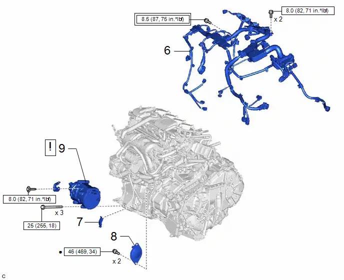
Procedure | Part Name Code |  |  |  |
|
|---|---|---|---|---|---|
6 |
ENGINE WIRE |
82121 |
- |
- |
- |
7 |
FLYWHEEL HOUSING SIDE COVER |
11363A |
- |
- |
- |
8 |
STARTER HOLE INSULATOR |
28193 |
- |
- |
- |
9 |
COMPRESSOR WITH MOTOR ASSEMBLY |
88370 |
 |
- |
- |
 |
Tightening torque for "Major areas involving basic Toyota Prius vehicle performance such as moving/turning/stopping" : N*m (kgf*cm, ft.*lbf) |
 |
N*m (kgf*cm, ft.*lbf): Specified torque |
● |
Non-reusable part |
- |
- |
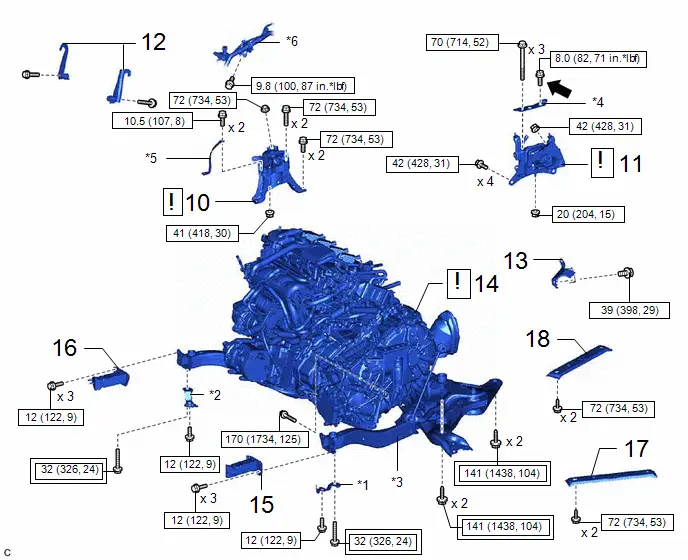
Procedure | Part Name Code |  |  |  |
|
|---|---|---|---|---|---|
10 |
ENGINE MOUNTING INSULATOR SUB-ASSEMBLY RH |
12305 |
 |
- |
- |
11 |
ENGINE MOUNTING INSULATOR LH |
12372A |
 |
- |
- |
12 |
REMOVE ENGINE HANGER |
- |
- |
- |
- |
13 |
WIRE HARNESS CLAMP BRACKET |
- |
- |
- |
- |
14 |
ENGINE ASSEMBLY WITH TRANSAXLE |
- |
 |
- |
- |
15 |
FRONT BUMPER EXTENSION SUB-ASSEMBLY LH |
52103A |
- |
- |
- |
16 |
FRONT BUMPER EXTENSION SUB-ASSEMBLY RH |
52102B |
- |
- |
- |
17 |
NO. 2 CROSSMEMBER GUSSET LH |
51322 |
- |
- |
- |
18 |
NO. 2 CROSSMEMBER GUSSET RH |
51321 |
- |
- |
- |
*1 |
CENTER RADIATOR SUPPORT LH |
*2 |
CENTER RADIATOR SUPPORT RH |
*3 |
FRONT SUSPENSION CROSSMEMBER SUB-ASSEMBLY |
*4 |
NO. 2 ENGINE MOUNTING STAY LH |
*5 |
NO. 2 EARTH WIRE |
*6 |
AIR CONDITIONER TUBE AND ACCESSORY ASSEMBLY |
 |
Tightening torque for "Major areas involving basic Toyota Prius vehicle performance such as moving/turning/stopping": N*m (kgf*cm, ft.*lbf) |
 |
N*m (kgf*cm, ft.*lbf): Specified torque |
 |
Adhesive 1324 |
★ |
Precoated part |
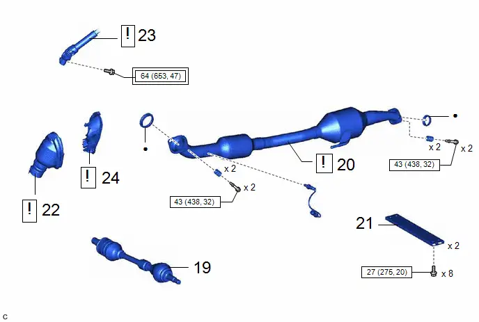
Procedure | Part Name Code |  |  |  |
|
|---|---|---|---|---|---|
19 |
FRONT DRIVE SHAFT ASSEMBLY |
- |
- |
- |
- |
20 |
FRONT EXHAUST PIPE ASSEMBLY |
17410 |
 |
- |
- |
21 |
FRONT FLOOR CENTER BRACE |
57533B |
- |
- |
- |
22 |
NO. 1 STEERING COLUMN HOLE COVER SUB-ASSEMBLY |
45025D |
 |
- |
- |
23 |
NO. 2 STEERING INTERMEDIATE SHAFT ASSEMBLY |
45260 |
 |
- |
- |
24 |
COLUMN HOLE COVER SILENCER SHEET |
45259A |
- |
- |
- |
 |
Tightening torque for "Major areas involving basic Toyota Prius vehicle performance such as moving/turning/stopping": N*m (kgf*cm, ft.*lbf) |
 |
N*m (kgf*cm, ft.*lbf): Specified torque |
● |
Non-reusable part |
- |
- |
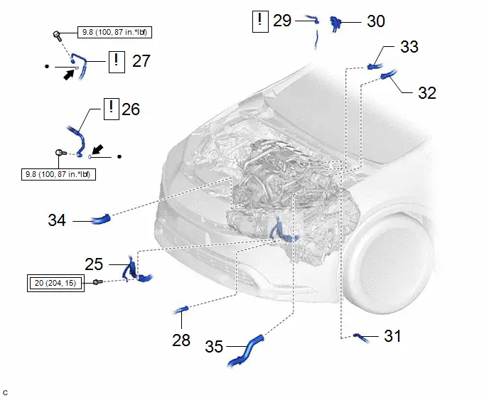
Procedure | Part Name Code |  |  |  |
|
|---|---|---|---|---|---|
25 |
NO. 7 ENGINE WIRE |
82127D |
- |
- |
- |
26 |
SUCTION HOSE SUB-ASSEMBLY |
88704 |
 |
- |
- |
27 |
DISCHARGE HOSE SUB-ASSEMBLY |
88703 |
 |
- |
- |
28 |
NO. 2 INVERTER COOLING OUTLET HOSE |
G922D |
- |
- |
- |
29 |
FUEL TUBE SUB-ASSEMBLY |
23901 |
 |
- |
- |
30 |
EFI FUEL PIPE CLAMP |
23842A |
- |
- |
- |
31 |
NO. 1 FUEL VAPOR FEED HOSE |
23826 |
- |
- |
- |
32 |
OUTLET HEATER WATER HOSE |
87246 |
- |
- |
- |
33 |
INLET HEATER WATER HOSE |
87245 |
- |
- |
- |
34 |
NO. 2 RADIATOR HOSE |
16572D |
- |
- |
- |
35 |
NO. 1 RADIATOR HOSE |
16571C |
- |
- |
- |
 |
Tightening torque for "Major areas involving basic Toyota Prius vehicle performance such as moving/turning/stopping": N*m (kgf*cm, ft.*lbf) |
 |
N*m (kgf*cm, ft.*lbf): Specified torque |
 |
Compressor oil ND-OIL 11 or equivalent |
● |
Non-reusable part |
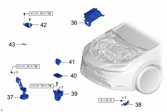
Procedure | Part Name Code |  |  |  |
|
|---|---|---|---|---|---|
36 |
INVERTER WITH CONVERTER ASSEMBLY |
G9200 |
- |
- |
- |
37 |
INLET NO. 1 AIR CLEANER |
17751 |
- |
- |
- |
38 |
AIR CLEANER BRACKET |
17771A |
- |
- |
- |
39 |
AIR CLEANER CASE SUB-ASSEMBLY |
17701 |
- |
- |
- |
40 |
AIR CLEANER FILTER ELEMENT SUB-ASSEMBLY |
17801 |
- |
- |
- |
41 |
THROTTLE BODY ASSEMBLY |
22210 |
- |
- |
- |
42 |
INLET NO. 2 AIR CLEANER |
17752 |
- |
- |
- |
43 |
NO. 8 WATER BY-PASS HOSE |
16296 |
- |
- |
- |
 |
N*m (kgf*cm, ft.*lbf): Specified torque |
- |
- |
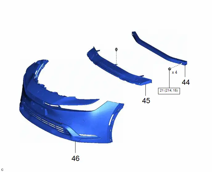
Procedure | Part Name Code |  |  |  |
|
|---|---|---|---|---|---|
44 |
NO. 2 FRONT BUMPER REINFORCEMENT |
52132A |
- |
- |
- |
45 |
FRONT BUMPER LOWER ABSORBER |
52618 |
- |
- |
- |
46 |
FRONT BUMPER ASSEMBLY |
- |
- |
- |
- |
 |
N*m (kgf*cm, ft.*lbf): Specified torque |
- |
- |
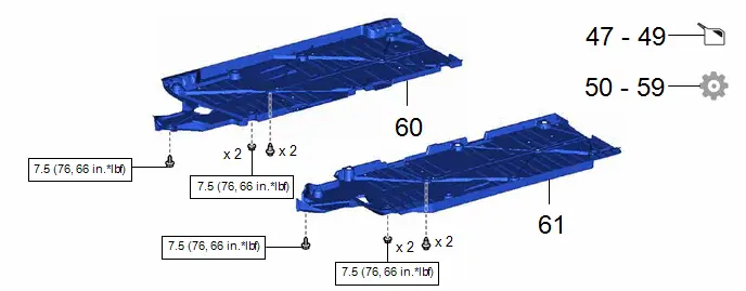
Procedure | Part Name Code |  |  |  |
|
|---|---|---|---|---|---|
47 |
ADD ENGINE OIL |
- |
- |
 |
- |
48 |
ADD HYBRID TRANSAXLE FLUID |
- |
- |
 |
- |
49 |
ADD ENGINE COOLANT (for Engine) |
- |
- |
 |
- |
50 |
CHARGE AIR CONDITIONING SYSTEM WITH REFRIGERANT |
- |
- |
- |
 |
51 |
CHECK ENGINE OIL LEVEL |
- |
- |
- |
 |
52 |
INSPECT HYBRID TRANSAXLE FLUID |
- |
- |
- |
 |
53 |
INSPECT FOR COOLANT LEAK (for Inverter) |
- |
- |
- |
 |
54 |
INSPECT FOR COOLANT LEAK (for Engine) |
- |
- |
- |
 |
55 |
WARM UP COMPRESSOR |
- |
- |
- |
 |
56 |
INSPECT FOR REFRIGERANT LEAK |
- |
- |
- |
 |
57 |
INSPECT FOR FUEL LEAK |
- |
- |
- |
 |
58 |
INSPECT FOR OIL LEAK |
- |
- |
- |
 |
59 |
INSPECT FOR EXHAUST GAS LEAK |
- |
- |
- |
 |
60 |
FRONT FLOOR COVER RH |
58165C |
- |
- |
- |
61 |
FRONT FLOOR COVER LH |
58166A |
- |
- |
- |
 |
N*m (kgf*cm, ft.*lbf): Specified torque |
- |
- |
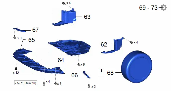
Procedure | Part Name Code |  |  |  |
|
|---|---|---|---|---|---|
62 |
REAR ENGINE UNDER COVER LH |
51444A |
- |
- |
- |
63 |
REAR ENGINE UNDER COVER RH |
51443C |
- |
- |
- |
64 |
NO. 1 ENGINE UNDER COVER ASSEMBLY |
51410 |
- |
- |
- |
65 |
CENTER ENGINE UNDER COVER |
51451A |
- |
- |
- |
66 |
FRONT WHEEL OPENING EXTENSION PAD LH |
53852B |
- |
- |
- |
67 |
FRONT WHEEL OPENING EXTENSION PAD RH |
53851D |
- |
- |
- |
68 |
FRONT WHEELS |
- |
 |
- |
- |
69 |
INSPECT IGNITION TIMING |
- |
- |
- |
 |
70 |
INSPECT ENGINE IDLE SPEED |
- |
- |
- |
 |
71 |
INSPECT CO/HC |
- |
- |
- |
 |
72 |
INSPECT AND ADJUST FRONT WHEEL ALIGNMENT |
- |
- |
- |
 |
73 |
CHECK SPEED SENSOR SIGNAL |
- |
- |
- |
 |
 |
N*m (kgf*cm, ft.*lbf): Specified torque |
- |
- |
PROCEDURE
1. INSTALL ENGINE HANGERS
 |
Click here |

2. REMOVE ENGINE ASSEMBLY FROM ENGINE STAND
3. INSTALL FLYWHEEL SUB-ASSEMBLY
 |
Click here |

4. INSTALL TRANSMISSION INPUT DAMPER ASSEMBLY
 |
Click here |

5. INSTALL ENGINE ASSEMBLY
 |
Click here |

6. INSTALL ENGINE WIRE
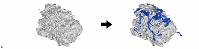
HINT:
The illustrations are representative examples, and details may differ.
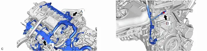
Torque:
Bolt (A) :
8 N·m {82 kgf·cm, 71 in·lbf}
Bolt (B) :
8,5 N·m {87 kgf·cm, 75 in·lbf}
7. INSTALL FLYWHEEL HOUSING SIDE COVER
Click here 
8. INSTALL STARTER HOLE INSULATOR
Click here 
9. INSTALL COMPRESSOR WITH MOTOR ASSEMBLY
 |
Click here |

10. INSTALL ENGINE MOUNTING INSULATOR SUB-ASSEMBLY RH
HINT:
Perform this procedure only when replacement of the engine mounting insulator sub-assembly RH is necessary.
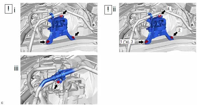
*a |
Temporarily Tighten |
- |
- |
(1) Temporarily install the engine mounting insulator sub-assembly RH to the Toyota Prius vehicle with the 2 bolts and nut.
(2) Tighten the 2 bolts and nut in the order shown in the illustration.
Torque:
72 N·m {734 kgf·cm, 53 ft·lbf}
(3) Connect the air conditioner tube and accessory assembly to the engine mounting insulator sub-assembly RH with the bolt.
Torque:
9,8 N·m {100 kgf·cm, 87 in·lbf}
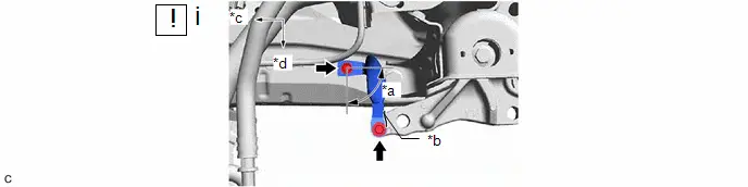
*a |
Installation Range |
*b |
Contact Point to Stop Rotation When Tightening |
*c |
Front of Toyota Prius Vehicle |
*d |
LH Side |
(1) Install the No. 2 earth wire to the engine mounting insulator sub-assembly RH and vehicle body with the 2 bolts as shown in the illustration.
Torque:
10,5 N·m {107 kgf·cm, 8 ft·lbf}
11. INSTALL ENGINE MOUNTING INSULATOR LH
HINT:
Perform this procedure only when replacement of the engine mounting insulator LH is necessary.
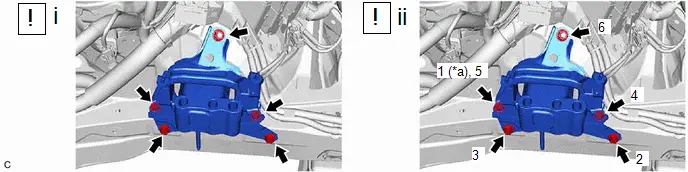
*a |
Temporarily Tighten |
- |
- |
(1) Temporarily install the engine mounting insulator LH to the Toyota Prius vehicle with the 4 bolts and nut..
(2) Tighten the 4 bolts and nut in the order shown in the illustration.
Torque:
42 N·m {428 kgf·cm, 31 ft·lbf}
12. REMOVE ENGINE HANGER
13. INSTALL WIRE HARNESS CLAMP BRACKET
Torque:
39 N·m {398 kgf·cm, 29 ft·lbf}
14. INSTALL ENGINE ASSEMBLY WITH TRANSAXLE
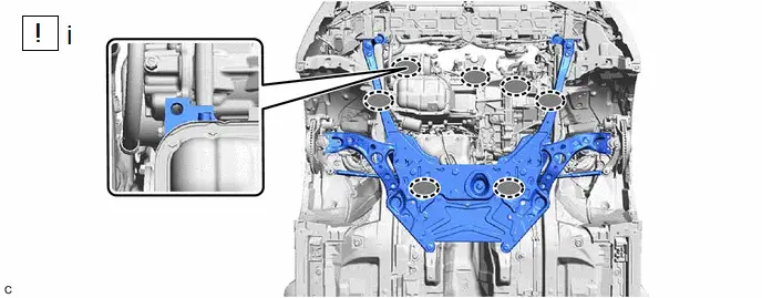
 |
Attachment Installation Position |
- |
- |
(1) Using height adjustment attachments and plate lift attachments to keep the engine assembly with transaxle and front suspension crossmember sub-assembly level, set an engine lifter underneath the engine assembly with transaxle and front suspension crossmember sub-assembly.
NOTICE:
- Using height adjustment attachments and plate lift attachments, keep the engine assembly with transaxle horizontal.
- Do not perform any procedures while the engine assembly is suspended because doing so may cause the engine assembly to drop, resulting in injury. However, the engine assembly needs to be suspended when it is installed to or removed from an engine stand.
- To prevent the oil pan sub-assembly from deforming, do not place any attachments under the oil pan sub-assembly of the engine assembly with transaxle.
*1 |
Center Radiator Support LH |
*2 |
Center Radiator Support RH |
*3 |
No. 2 Engine Mounting Stay LH |
- |
- |
 |
Bolt |
 |
Nut |
(1) Operate the engine lifter and install the engine assembly with transaxle to the Toyota Prius vehicle.
CAUTION:
Do not raise the engine assembly with transaxle more than necessary. If the engine is raised excessively, the vehicle may also be lifted up.
NOTICE:
- Make sure that the engine assembly with transaxle is clear of all wiring and hoses.
- While raising the engine assembly with transaxle into the Toyota Prius vehicle, do not allow it to contact the vehicle.
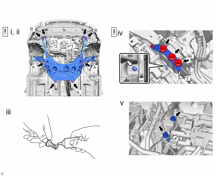
(2) Install the front suspension crossmember sub-assembly, center radiator support LH and center radiator support RH to the vehicle with the 8 bolts.
Torque:
Bolt (A) :
141 N·m {1438 kgf·cm, 104 ft·lbf}
Bolt (B) :
32 N·m {326 kgf·cm, 24 ft·lbf}
Bolt (C) :
12 N·m {122 kgf·cm, 9 ft·lbf}
(3) Apply adhesive to 2 or 3 threads at the end of each of the bolt (D).
Adhesive:
Toyota Genuine Adhesive 1324, Three Bond 1324 or equivalent
(4) Install the engine mounting insulator LH and No. 2 engine mounting stay LH to the hybrid Toyota Prius vehicle transaxle assembly with the 4 bolts and nut in the order shown in the illustration.
Torque:
Bolt (A), (B), (C) :
70 N·m {714 kgf·cm, 52 ft·lbf}
Bolt (D) :
8 N·m {82 kgf·cm, 71 in·lbf}
Nut :
20 N·m {204 kgf·cm, 15 ft·lbf}
NOTICE:
Temporarily tighten the bolt (A), and then fully tighten the 4 bolts in the order of (D), (A), (B) and (C).
(5) Install the engine mounting insulator sub-assembly RH to the engine mounting bracket RH with the 2 bolts and nut.
Torque:
Bolt :
72 N·m {734 kgf·cm, 53 ft·lbf}
Nut :
41 N·m {418 kgf·cm, 30 ft·lbf}
15. INSTALL FRONT BUMPER EXTENSION SUB-ASSEMBLY LH
Torque:
12 N·m {122 kgf·cm, 9 ft·lbf}
16. INSTALL FRONT BUMPER EXTENSION SUB-ASSEMBLY RH
Torque:
12 N·m {122 kgf·cm, 9 ft·lbf}
17. INSTALL NO. 2 CROSSMEMBER GUSSET LH
Torque:
72 N·m {734 kgf·cm, 53 ft·lbf}
18. INSTALL NO. 2 CROSSMEMBER GUSSET RH
Torque:
72 N·m {734 kgf·cm, 53 ft·lbf}
19. INSTALL FRONT DRIVE SHAFT ASSEMBLY
Click here 
20. INSTALL FRONT EXHAUST PIPE ASSEMBLY
 |
Click here |

21. INSTALL FRONT FLOOR CENTER BRACE
Click here 
22. CONNECT NO. 1 STEERING COLUMN HOLE COVER SUB-ASSEMBLY
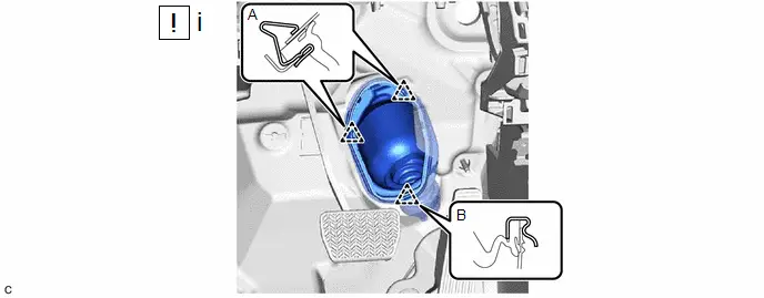
(1) Connect the No. 1 steering column hole cover sub-assembly by the below procedure.
1. Engage the clip (B) to the Toyota Prius vehicle body.
2. Engage the clip (A) to install the No. 1 steering column hole cover sub-assembly to the vehicle body.
NOTICE:
- Be careful not to damage the lip of the No. 1 steering column hole cover sub-assembly.
- Check that the No. 1 steering column hole cover sub-assembly is securely installed.
- Check that the No. 1 steering column hole cover sub-assembly and Toyota Prius vehicle body are in close contact with one another.
23. CONNECT NO. 2 STEERING INTERMEDIATE SHAFT ASSEMBLY
 |
Click here |


24. INSTALL COLUMN HOLE COVER SILENCER SHEET
25. CONNECT NO. 7 ENGINE WIRE
Torque:
20 N·m {204 kgf·cm, 15 ft·lbf}
26. CONNECT SUCTION HOSE SUB-ASSEMBLY
 |
Click here |

27. CONNECT DISCHARGE HOSE SUB-ASSEMBLY
 |
Click here |

28. CONNECT NO. 2 INVERTER COOLING OUTLET HOSE
29. CONNECT FUEL TUBE SUB-ASSEMBLY
 |
Click here |

30. INSTALL EFI FUEL PIPE CLAMP
31. CONNECT NO. 1 FUEL VAPOR FEED HOSE
32. CONNECT OUTLET HEATER WATER HOSE
33. CONNECT INLET HEATER WATER HOSE
34. CONNECT NO. 2 RADIATOR HOSE
35. CONNECT NO. 1 RADIATOR HOSE
36. INSTALL INVERTER WITH CONVERTER ASSEMBLY
Click here 
37. INSTALL INLET NO. 1 AIR CLEANER
Click here 
38. INSTALL AIR CLEANER BRACKET
Click here 
39. INSTALL AIR CLEANER CASE SUB-ASSEMBLY
Click here 
40. INSTALL AIR CLEANER FILTER ELEMENT SUB-ASSEMBLY
41. INSTALL THROTTLE BODY ASSEMBLY
Click here 
42. INSTALL INLET NO. 2 AIR CLEANER
Click here 
43. CONNECT NO. 8 WATER BY-PASS HOSE
44. INSTALL NO. 2 FRONT BUMPER REINFORCEMENT
Click here 
45. INSTALL FRONT BUMPER LOWER ABSORBER
46. INSTALL FRONT BUMPER ASSEMBLY
Click here 
47. ADD ENGINE OIL
Click here 
48. ADD HYBRID TRANSAXLE FLUID
Click here 

49. ADD ENGINE COOLANT (for Engine)
Click here 
50. CHARGE AIR CONDITIONING SYSTEM WITH REFRIGERANT
- for HFC-134a (R134a):
Click here

- for HFO-1234yf (R1234yf):
Click here


51. CHECK ENGINE OIL LEVEL
Click here 
52. INSPECT HYBRID TRANSAXLE FLUID
Click here 

53. INSPECT FOR COOLANT LEAK (for Inverter)
Click here 
54. INSPECT FOR COOLANT LEAK (for Engine)
Click here 
55. WARM UP COMPRESSOR
- for HFC-134a (R134a):
Click here

- for HFO-1234yf (R1234yf):
Click here


56. INSPECT FOR REFRIGERANT LEAK
- for HFC-134a (R134a):
Click here

- for HFO-1234yf (R1234yf):
Click here


57. INSPECT FOR FUEL LEAK
Click here 
58. INSPECT FOR OIL LEAK
Click here 
59. INSPECT FOR EXHAUST GAS LEAK
Click here 
60. INSTALL FRONT FLOOR COVER RH
Click here 
61. INSTALL FRONT FLOOR COVER LH
Click here 
62. INSTALL REAR ENGINE UNDER COVER LH
63. INSTALL REAR ENGINE UNDER COVER RH
64. INSTALL NO. 1 ENGINE UNDER COVER ASSEMBLY
65. INSTALL CENTER ENGINE UNDER COVER
Torque:
7,5 N·m {76 kgf·cm, 66 in·lbf}
66. INSTALL FRONT WHEEL OPENING EXTENSION PAD LH
67. INSTALL FRONT WHEEL OPENING EXTENSION PAD RH
68. INSTALL FRONT WHEELS
 |
Click here |

69. INSPECT IGNITION TIMING
Click here 
70. INSPECT ENGINE IDLE SPEED
Click here 
71. INSPECT CO/HC
Click here 
72. INSPECT AND ADJUST FRONT WHEEL ALIGNMENT
Click here 
73. CHECK SPEED SENSOR SIGNAL
Click here 