Fuel Pump
- Removal
- Disassembly
- Inspection
- Reassembly
- Installation
Removal
REMOVAL
The necessary procedures (adjustment, calibration, initialization or registration) that must be performed after parts are removed and installed, or replaced during fuel pump removal/installation are shown below.
Necessary Procedures After Parts Removed/Installed/ReplacedReplaced Part or Performed Procedure | Necessary Procedure | Effect/Inoperative Function when Necessary Procedure not Performed | Link |
|---|---|---|---|
Replacement of fuel pump |
Inspection after repair |
|
 |
CAUTION:
- Never perform work on fuel system components near any possible ignition sources.
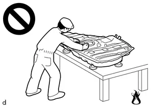
- Vaporized fuel could ignite, resulting in a serious accident.
- Do not perform work on fuel system components without first disconnecting the cable from the negative (-) auxiliary battery terminal.
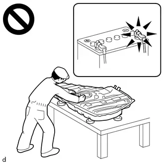
- Sparks could cause vaporized fuel to ignite, resulting in a serious accident.
HINT:
When the cable is disconnected / reconnected to the auxiliary battery terminal, systems temporarily stop operating. However, each system has a function that completes learning the first time the system is used.
Learning completes when Toyota Prius vehicle is drivenEffect/Inoperative Function when Necessary Procedure not Performed | Necessary Procedure | Link |
|---|---|---|
Front Camera System |
Drive the Toyota Prius vehicle straight ahead at 35 km/h or more for 5 seconds or more. |
 |
Effect/Inoperative Function when Necessary Procedure not Performed | Necessary Procedure | Link |
|---|---|---|
| *1: w/o Power Back Door System *2: w/ Power Back Door System |
||
Power Door Lock Control System*1
|
Perform door unlock operation with door control switch or electrical key transmitter sub-assembly switch. |
 |
Power Back Door System*2 |
Reset back door close position |
 |
Air Conditioning System |
After the ignition switch is turned to ON, the servo motor standard position is recognized. |
- |
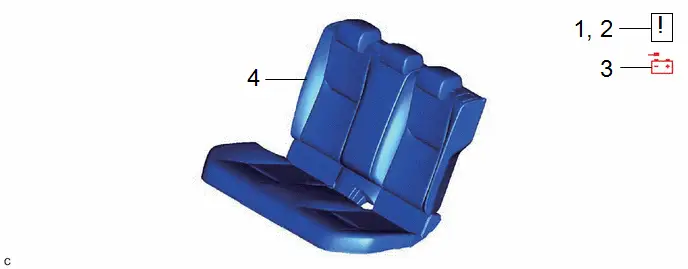
Procedure | Part Name Code |  |  |  |
|
|---|---|---|---|---|---|
1 |
PRECAUTION |
- |
 |
- |
- |
2 |
DISCHARGE FUEL SYSTEM PRESSURE |
- |
 |
- |
- |
3 |
DISCONNECT CABLE FROM NEGATIVE AUXILIARY BATTERY TERMINAL |
- |
- |
- |
- |
4 |
REAR SEAT ASSEMBLY |
- |
- |
- |
- |
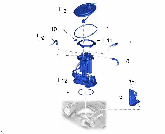
Procedure | Part Name Code |  |  |  |
|
|---|---|---|---|---|---|
5 |
CENTER REAR SEAT BACK HINGE SUB-ASSEMBLY |
71305A |
- |
- |
- |
6 |
REAR FLOOR SERVICE HOLE COVER |
58325E |
 |
- |
- |
7 |
NO. 1 FUEL EVAPORATION TUBE SUB-ASSEMBLY |
77026A |
- |
- |
- |
8 |
CHARCOAL CANISTER OUTLET HOSE |
77754B |
- |
- |
- |
9 |
FUEL TANK MAIN TUBE SUB-ASSEMBLY |
77209F |
 |
- |
- |
10 |
NO. 1 FUEL TUBE CLAMP |
77285M |
- |
- |
- |
11 |
FUEL PUMP GAUGE RETAINER |
77144 |
 |
- |
- |
12 |
FUEL SUCTION TUBE WITH PUMP AND GAUGE ASSEMBLY |
77020A |
 |
- |
- |
*1 |
TUBE JOINT CLIP |
- |
- |
● |
Non-reusable part |
- |
- |
PROCEDURE
1. PRECAUTION
 |
NOTICE: After the ignition switch is turned off, there may be a waiting time before disconnecting the negative (-) auxiliary battery terminal. Click here |

2. DISCHARGE FUEL SYSTEM PRESSURE
Click here 
3. DISCONNECT CABLE FROM NEGATIVE AUXILIARY BATTERY TERMINAL
Click here 
4. REMOVE REAR SEAT ASSEMBLY
Click here 

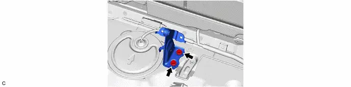
5. REMOVE CENTER REAR SEAT BACK HINGE SUB-ASSEMBLY
6. REMOVE REAR FLOOR SERVICE HOLE COVER
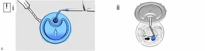
(1) Using a clip remover with its tip wrapped with protective tape, remove the rear floor service hole cover and butyl tape.
(2) Disconnect the fuel suction tube with pump andgauge assembly connector.
7. DISCONNECT NO. 1 FUEL EVAPORATION TUBE SUB-ASSEMBLY

8. DISCONNECT CHARCOAL CANISTER OUTLET HOSE
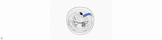
9. DISCONNECT FUEL TANK MAIN TUBE SUB-ASSEMBLY
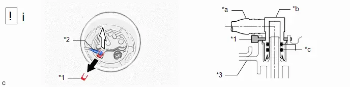
*1 |
Tube Joint Clip |
*2 |
Fuel Tank Main Tube Sub-assembly |
*3 |
Fuel Suction Plate Sub-assembly |
- |
- |
*a |
Nylon Tube |
*b |
Fuel Tube Joint |
*c |
O-ring |
- |
- |
 |
Pull off |
 |
Pull off |
(1) Remove the tube joint clip, and pull off the fuel tube joint of the fuel tank main tube sub-assembly.
NOTICE:
- Remove any foreign matter on the fuel tube joint before performing this work.
- Do not scratch or allow any foreign matter to get on the parts when disconnecting them as the fuel tube connector has O-rings that seal the pipe (fuel pipe).
- Be sure to disconnect the fuel tube joint by hand.
- Do not bend, twist, pinch or kink the nylon tube.
- Cover the disconnected fuel tube joint with a plastic bag to prevent damage and contamination.
- If the fuel tube joint and fuel suction plate sub-assembly are stuck, push and pull to release them.
10. REMOVE NO. 1 FUEL TUBE CLAMP
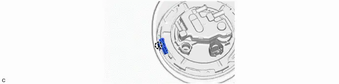
11. REMOVE FUEL PUMP GAUGE RETAINER
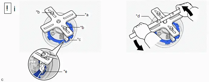
*a |
SST (Plate) |
*b |
SST (Bolt) |
*c |
SST (Claw) |
*d |
SST (Handle) |
*e |
Insertion Point |
- |
- |
(1) Remove the fuel pump gauge retainer.
1. Temporarily install SST (plate) and SST (claw) to the fuel pump gauge retainer.
SST: 09808-01071
SST: 09808-14031
09808-01030
09808-01090
HINT:
Securely insert the ends of SST (claw) into the insertion points in the fuel pump gauge retainer.
2. While firmly pressing SST (claw) into the insertion points in the fuel pump gauge retainer, tighten SST (bolt).
3. Install SST (handle) to SST (plate).
SST: 09808-14031
09808-01010
4. Lightly press down on SST to prevent it from separating from the fuel pump gauge retainer. While pressing down on SST, rotate SST (handle) slowly to loosen the fuel pump gauge retainer.
NOTICE:
- Do not use any tools other than specified as this may result in damage to the fuel pump gauge retainer or fuel tank sub-assembly.
- Do not press down on SST excessively as this may make the fuel pump gauge retainer hard to rotate, and may damage components.
- Make sure to rotate SST (handle) horizontally. If it is rotated at an angle, SST may come off.
- Do not spin SST too fast or use an impact wrench as this may result in damage to components.
- If SST comes off of the fuel pump gauge retainer, loosen SST (bolt) and reinstall SST.
5. While pressing down on the fuel suction tube with pump and gauge assembly, remove the fuel pump gauge retainer.
12. REMOVE FUEL SUCTION TUBE WITH PUMP AND GAUGE ASSEMBLY
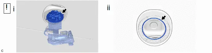
(1) Remove the fuel suction tube with pump and gauge assembly from the fuel tank sub-assembly.
NOTICE:
Be careful not to bend the arm of the fuel sender gauge assembly.
(2) Remove the fuel suction tube set gasket from the fuel tank sub-assembly.
Disassembly
DISASSEMBLY
NOTICE:
Do not disconnect the tube shown in the illustration when disassembling the fuel suction tube with pump and gauge assembly. Doing so will cause reassembly of the fuel suction tube with pump and gauge assembly to be impossible as the tube is pressed into the fuel suction plate sub-assembly.
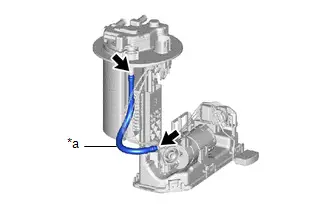
*a |
Tube |
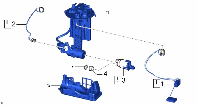
Procedure | Part Name Code |  |  |  |
|
|---|---|---|---|---|---|
1 |
FUEL SENDER GAUGE ASSEMBLY |
83320 |
 |
- |
- |
2 |
FUEL PUMP HARNESS |
77785 |
 |
- |
- |
3 |
FUEL PUMP |
23221 |
 |
- |
- |
4 |
FUEL PUMP SPACER |
23225A |
- |
- |
- |
*1 |
FUEL SUCTION PLATE SUB-ASSEMBLY |
*2 |
FUEL SUB-TANK SUB-ASSEMBLY |
● |
Non-reusable part |
- |
- |
PROCEDURE
1. REMOVE FUEL SENDER GAUGE ASSEMBLY
 |
Click here |

2. REMOVE FUEL PUMP HARNESS
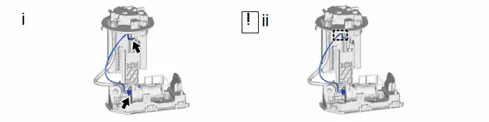
(1) Disconnect the 2 fuel pump harness connectors.
(2) Disengage the clamp to remove the fuel pump harness from the fuel suction tube with pump and gauge assembly.
NOTICE:
- Do not damage the wire harness.
- When disengaging each wire harness from the clamp, disengage one wire at a time.
3. REMOVE FUEL PUMP
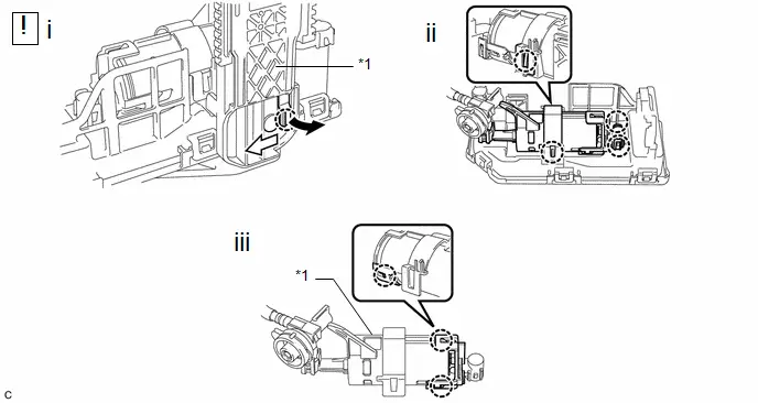
*1 |
Fuel Suction Plate Sub-assembly |
- |
- |
 |
Pull |
 |
Slide |
(1) Disengage the claw and slide the fuel suction plate sub-assembly and then separate it from the fuel sub-tank sub-assembly.
(2) Disengage the 4 claws and remove the fuel suction plate sub-assembly from the fuel sub-tank sub-assembly.
(3) Disengage the 3 claws, and remove the fuel pump from the fuel suction plate sub-assembly.
4. REMOVE FUEL PUMP SPACER

*1 |
O-ring |
*2 |
Fuel Pump Spacer |
Inspection
INSPECTION
PROCEDURE
1. INSPECT FUEL PUMP
(a) Check the resistance. (1) Measure the resistance according to the value(s) in the table below. Standard Resistance:
If the result is not as specified, replace the fuel pump. |
|
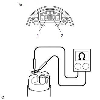
(b) Check the operation.
(1) Apply auxiliary battery voltage to both terminals. Check that the fuel pump operates.
NOTICE:
- Perform this test within 10 seconds to prevent the coil from burning out.
- Keep the fuel pump as far away from the auxiliary battery as possible.
- Always switch the voltage on and off at the auxiliary battery side, not the fuel pump side.
If the fuel pump does not operate, replace the fuel pump.
Reassembly
REASSEMBLY
COMPONENTS (REASSEMBLY)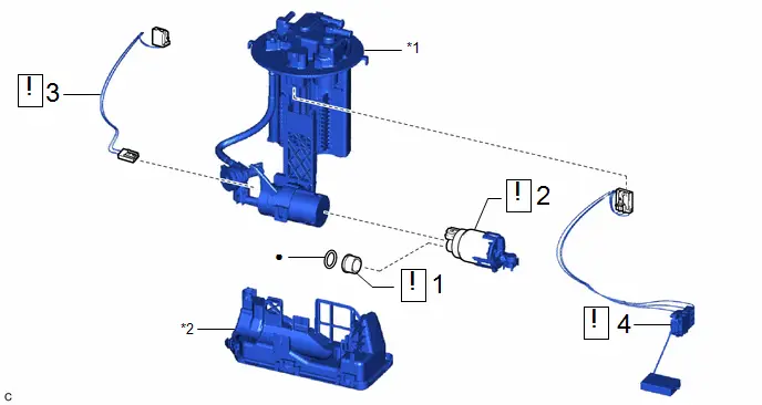
Procedure | Part Name Code |  |  |  |
|
|---|---|---|---|---|---|
1 |
FUEL PUMP SPACER |
23225A |
 |
- |
- |
2 |
FUEL PUMP |
23221 |
 |
- |
- |
3 |
FUEL PUMP HARNESS |
77785 |
 |
- |
- |
4 |
FUEL SENDER GAUGE ASSEMBLY |
83320 |
 |
- |
- |
*1 |
FUEL SUCTION PLATE SUB-ASSEMBLY |
*2 |
FUEL SUB-TANK SUB-ASSEMBLY |
● |
Non-reusable part |
- |
- |
PROCEDURE
1. INSTALL FUEL PUMP SPACER
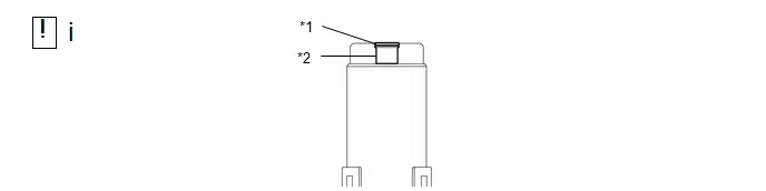
*1 |
O-ring |
*2 |
Fuel Pump Spacer |
(1) Apply gasoline to a new O-ring. Then install the O-ring and fuel pump spacer to the fuel pump.
2. INSTALL FUEL PUMP
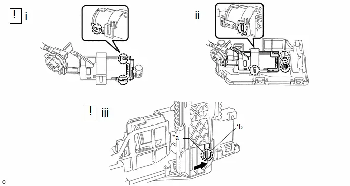
*a |
Protrusion |
*b |
Installation Hole |
 |
Slide |
- |
- |
(1) Engage the 3 claws to install the fuel pump to the fuel suction plate sub-assembly.
NOTICE:
- Make sure that the O-ring is not cut or pinched during the installation.
- Securely engage the claw.
(2) Engage the 4 claws to install the fuel suction plate sub-assembly to the fuel sub-tank sub-assembly.
(3) Align the protrusion of the fuel sub-tank sub-assembly with the installation hole of the fuel suction plate sub-assembly and then slide the fuel suction plate sub-assembly to install it the fuel sub-tank sub-assembly.
3. INSTALL FUEL PUMP HARNESS
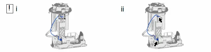
(1) Engage the clamp to install the fuel pump harness to the fuel suction tube with pump and gauge assembly.
NOTICE:
- Do not damage the wire harness.
- When engaging each wire harness to the clamp, engage one wire at a time.
(2) Connect the 2 fuel pump harness connectors.
4. INSTALL FUEL SENDER GAUGE ASSEMBLY
 |
Click here |

Installation
INSTALLATION
COMPONENTS (INSTALLATION)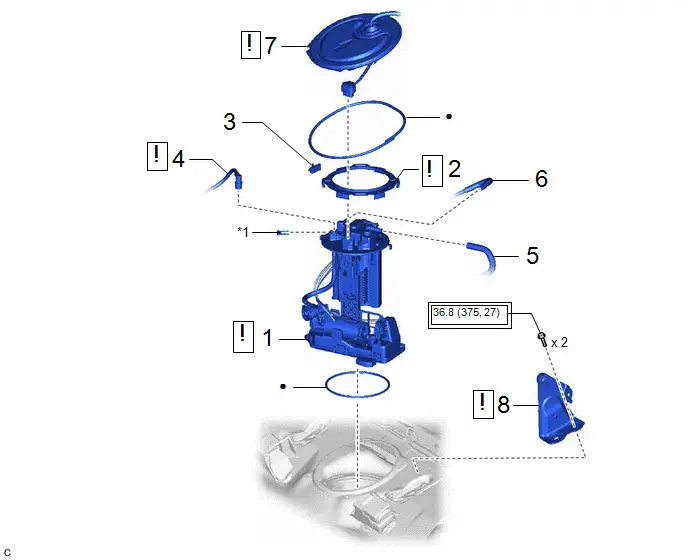
Procedure | Part Name Code |  |  |  |
|
|---|---|---|---|---|---|
1 |
FUEL SUCTION TUBE WITH PUMP AND GAUGE ASSEMBLY |
77020A |
 |
- |
- |
2 |
FUEL PUMP GAUGE RETAINER |
77144 |
 |
- |
- |
3 |
NO. 1 FUEL TUBE CLAMP |
77285M |
- |
- |
- |
4 |
FUEL TANK MAIN TUBE SUB-ASSEMBLY |
77209F |
 |
- |
- |
5 |
CHARCOAL CANISTER OUTLET HOSE |
77754B |
- |
- |
- |
6 |
NO. 1 FUEL EVAPORATION TUBE SUB-ASSEMBLY |
77026A |
- |
- |
- |
7 |
REAR FLOOR SERVICE HOLE COVER |
58325E |
 |
- |
- |
8 |
CENTER REAR SEAT BACK HINGE SUB-ASSEMBLY |
71305A |
 |
- |
- |
*1 |
TUBE JOINT CLIP |
- |
- |
 |
Tightening torque for "Major areas involving basic Toyota Prius vehicle performance such as moving/turning/stopping": N*m (kgf*cm, ft.*lbf) |
● |
Non-reusable part |
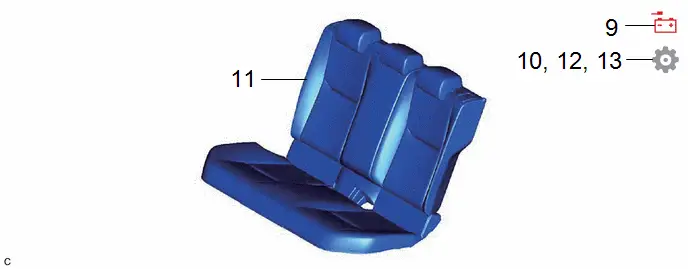
Procedure | Part Name Code |  |  |  |
|
|---|---|---|---|---|---|
9 |
CONNECT CABLE TO NEGATIVE AUXILIARY BATTERY TERMINAL |
- |
- |
- |
- |
10 |
INSPECT FOR FUEL LEAK |
- |
- |
- |
 |
11 |
REAR SEAT ASSEMBLY |
- |
- |
- |
- |
12 |
PERFORM INITIALIZATION |
- |
- |
- |
 |
13 |
INITIALIZATION AFTER RECONNECTING AUXILIARY BATTERY TERMINAL |
- |
- |
- |
 |
PROCEDURE
1. INSTALL FUEL SUCTION TUBE WITH PUMP AND GAUGE ASSEMBLY
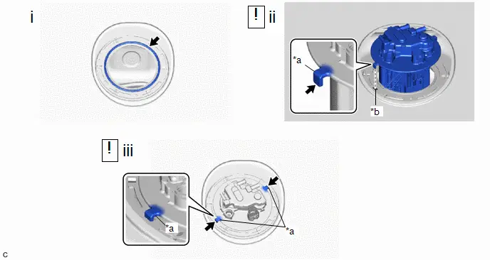
*a |
Protrusion |
*b |
Notch |
(1) Install a new fuel suction tube set gasket to the fuel tank sub-assembly.
(2) Set the fuel suction tube with pump and gauge assembly to the fuel tank sub-assembly.
NOTICE:
- Be careful not to bend the arm of the fuel sender gauge assembly.
- To avoid applying excessive force to the tip of the fuel sender gauge assembly, tilt the fuel sub-tank sub-assembly diagonally and insert it into the fuel tank sub-assembly as shown in the illustration.
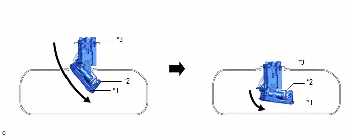
*1 |
Fuel Sender Gauge Assembly |
*2 |
Fuel Sub-tank Sub-assembly |
*3 |
Fuel Suction Plate Sub-assembly |
- |
- |
(3) Align the protrusions of the fuel suction tube with pump and gauge assembly with the notches in the fuel tank sub-assembly.
2. INSTALL FUEL PUMP GAUGE RETAINER
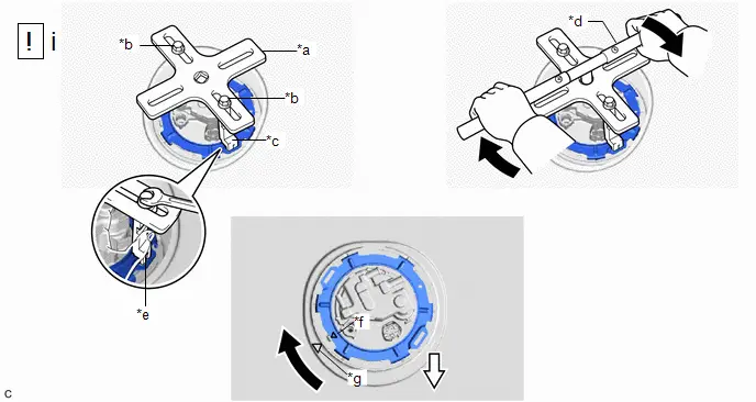
*a |
SST (Plate) |
*b |
SST (Bolt) |
*c |
SST (Claw) |
*d |
SST (Handle) |
*e |
Insertion Point |
*f |
Triangle Mark (Fuel Pump Gauge Retainer) |
*g |
Triangle Mark (Fuel Tank Sub-assembly) |
- |
- |
 |
Tighten |
 |
Front Side of Toyota Prius Vehicle |
(1) Install the fuel pump gauge retainer.
1. While pressing down on the fuel suction tube with pump and gauge assembly, temporarily install the fuel pump gauge retainer.
2. Temporarily install SST (plate) and SST (claw) to the fuel pump gauge retainer.
SST: 09808-01071
SST: 09808-14031
09808-01030
09808-01090
HINT:
Securely insert the ends of SST (claw) into the insertion points in the fuel pump gauge retainer.
3. While firmly pressing SST (claw) into the insertion points in the fuel pump gauge retainer, tighten SST (bolt).
4. Install SST (handle) to SST (plate).
SST: 09808-14031
09808-01010
5. Using SST, rotate the fuel pump gauge retainer so that the triangle mark on the fuel pump gauge retainer is aligned with the triangle mark on the fuel tank sub-assembly to install the fuel suction tube with pump and gauge assembly to the fuel tank sub-assembly.
NOTICE:
- Do not use any tools other than specified as this may result in damage to the fuel pump gauge retainer or fuel tank sub-assembly.
- Do not press down on SST excessively as this may make the fuel pump gauge retainer hard to rotate, and may damage components.
- Make sure to rotate SST (handle) horizontally. If it is rotated at an angle, SST may come off.
- Do not spin SST too fast or use an impact wrench as this may result in damage to components.
- If SST comes off of the fuel pump gauge retainer, loosen SST (bolt) and reinstall SST.
- Make sure that the fuel suction tube set gasket does not come off.
3. INSTALL NO. 1 FUEL TUBE CLAMP
4. CONNECT FUEL TANK MAIN TUBE SUB-ASSEMBLY
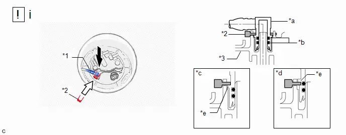
*1 |
Fuel Tank Main Tube Sub-assembly |
*2 |
Tube Joint Clip |
*3 |
Fuel Suction Plate Sub-assembly |
- |
- |
*a |
Fuel Tube Joint |
*b |
O-ring |
*c |
Correct |
*d |
Incorrect |
*e |
Collar |
- |
- |
 |
Insert |
 |
Insert |
(1) Push the fuel tube joint onto the plug of the fuel suction plate sub-assembly, then install the tube joint clip.
NOTICE:
- Check that there are no scratches or foreign matter around the connecting parts of the fuel tube joint and plug before performing this work.
- Check that the fuel tube joint is securely inserted to the end.
- Check that the tube joint clip is on the collar of the fuel tube joint.
- After installing the tube joint clip, check that the fuel tank main tube sub-assembly is securely connected by pulling on it.
5. CONNECT CHARCOAL CANISTER OUTLET HOSE
6. CONNECT NO. 1 FUEL EVAPORATION TUBE SUB-ASSEMBLY
7. INSTALL REAR FLOOR SERVICE HOLE COVER
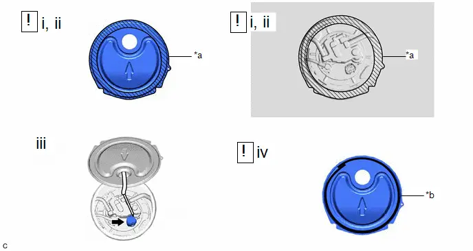
*a |
Cleaning Area |
*b |
Butyl Tape Adhesion Area |
(1) Remove any remaining butyl tape from the rear floor service hole cover and Toyota Prius vehicle body.
(2) Clean the installation surfaces of the rear floor service hole cover and vehicle body.
(3) Connect the fuel suction tube with pump and gauge assembly connector.
(4) Install the rear floor service hole cover with new butyl tape.
8. INSTALL CENTER REAR SEAT BACK HINGE SUB-ASSEMBLY
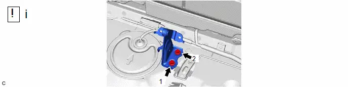
(1) Install the center rear seat back hinge sub-assembly to the Toyota Prius vehicle body with the 2 bolts in the order shown in the illustration.
Torque:
37 N·m {375 kgf·cm, 27 ft·lbf}
9. CONNECT CABLE TO NEGATIVE AUXILIARY BATTERY TERMINAL
Click here 
10. INSPECT FOR FUEL LEAK
Click here 
11. INSTALL REAR SEAT ASSEMBLY
Click here 

12. PERFORM INITIALIZATION
(a) Perform "Inspection After Repair" after replacing the fuel pump.
Click here 
13. INITIALIZATION AFTER RECONNECTING AUXILIARY BATTERY TERMINAL
HINT:
When disconnecting and reconnecting the auxiliary battery, there is an automatic learning function that completes learning when the respective system is used.
Click here 
