Inner Mirror Monitor Camera
Removal
REMOVAL
The necessary procedures (adjustment, calibration, initialization or registration) that must be performed after parts are removed and installed, or replaced during rear television camera assembly removal/installation are shown below.
Necessary Procedures After Parts Removed/Installed/ReplacedReplaced Part or Performed Procedure | Necessary Procedures | Effect/Inoperative Function When Necessary Procedures are not Performed | Link |
|---|---|---|---|
| *1: Even when not replacing the part, it is necessary to perform the specified necessary procedures after installation. *2: w/ Rear Camera Cleaner System |
|||
Rear television camera assembly |
|
Parking Assist Monitor System |
 |
Rear television camera view adjustment*1 |
Parking Support Brake System |
 |
|
Panoramic View Monitor System |
 |
||
Advanced Park |
 |
||
Camera cleaner setting operation*2 |
Multimedia switch is not displayed |
 |
|

Procedure | Part Name Code |  |  |  |
|
|---|---|---|---|---|---|
1 |
REAR LIGHT ASSEMBLY |
- |
- |
- |
- |
2 |
TELEVISION CAMERA ASSEMBLY |
86790D |
- |
- |
- |
3 |
INNER MIRROR CAMERA ASSEMBLY |
867C0B |
 |
- |
- |
*1 |
Screw grommet |
- |
- |
● |
Non-reusable part |
- |
- |
PROCEDURE
1. REMOVE REAR LIGHT ASSEMBLY
Click here 
2. REMOVE TELEVISION CAMERA ASSEMBLY
Click here 
3. REMOVE INNER MIRROR CAMERA ASSEMBLY

 |
Remove in this Direction |
- |
- |
(1) Using a T5 "TORX" socket wrench, remove the 2 screws.
(2) Remove the inner mirror camera assembly as shown in the illustration.
Installation
INSTALLATION
COMPONENTS (INSTALLATION)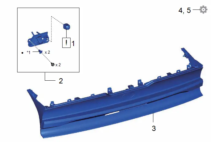
Procedure | Part Name Code |  |  |  |
|
|---|---|---|---|---|---|
1 |
INNER MIRROR CAMERA ASSEMBLY |
867C0B |
 |
- |
- |
2 |
TELEVISION CAMERA ASSEMBLY |
86790D |
- |
- |
- |
3 |
REAR LIGHT ASSEMBLY |
- |
- |
- |
- |
4 |
PERFORM CALIBRATION |
- |
- |
- |
- |
5 |
PERFORM CALIBRATION (w/ Rear Camera Cleaner System) |
- |
- |
- |
- |
*1 |
Screw grommet |
- |
- |
● |
Non-reusable part |
- |
- |
PROCEDURE
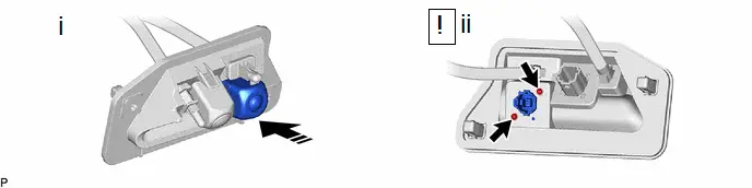
1. INSTALL INNER MIRROR CAMERA ASSEMBLY RR
 |
Remove in this Direction |
- |
- |
(1) Temporarily install the inner mirror camera assembly as shown in the illustration.
(2) Using a T5 "TORX" socket wrench, install the inner mirror camera assembly with the 2 screws.
2. INSTALL TELEVISION CAMERA ASSEMBLY
3. INSTALL REAR LIGHT ASSEMBLY
4. PERFORM CALIBRATION
(a) w/ Parking Assist Monitor System:
Click here 
(b) w/ Parking Support Brake System:
Click here 
(c) w/ Panoramic View Monitor System:
Click here 
(d) w/ Advanced Park:
Click here 
5. PERFORM CALIBRATION (w/ Rear Camera Cleaner System)
Click here 