High Mounted Stop Light Assembly
- Removal
- Inspection
- Installation
Removal
REMOVAL
The necessary procedures (adjustment, calibration, initialization or registration) that must be performed after parts are removed and installed, or replaced during high mounted stop light assembly removal/installation are shown below.
Necessary Procedures After Parts Removed/Installed/ReplacedReplaced Part or Performed Procedure | Necessary Procedures | Effect/Inoperative Function When Necessary Procedures are not Performed | Link |
|---|---|---|---|
| *1: Even when not replacing the part, it is necessary to perform the specified necessary procedures after installation. | |||
|
Reset back door close position |
Power Back Door System |
 |
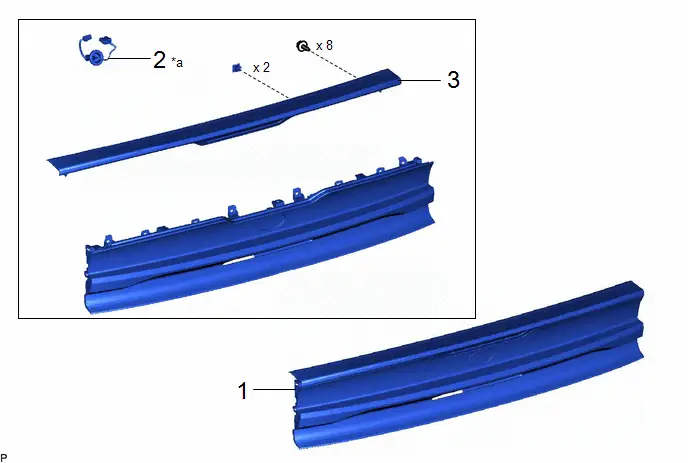
Procedure | Part Name Code |  |  |  |
|
|---|---|---|---|---|---|
1 |
REAR LIGHT ASSEMBLY |
- |
- |
- |
- |
2 |
CENTER STOP LIGHT CORD ASSEMBLY |
81935D |
- |
- |
- |
3 |
CENTER STOP LIGHT ASSEMBLY |
81570 |
- |
- |
- |
*a |
The illustration shown is an example only. The illustration may differ from the actual parts according to the model. |
- |
- |
PROCEDURE
1. REMOVE REAR LIGHT ASSEMBLY
Click here 
2. REMOVE CENTER STOP LIGHT CORD ASSEMBLY
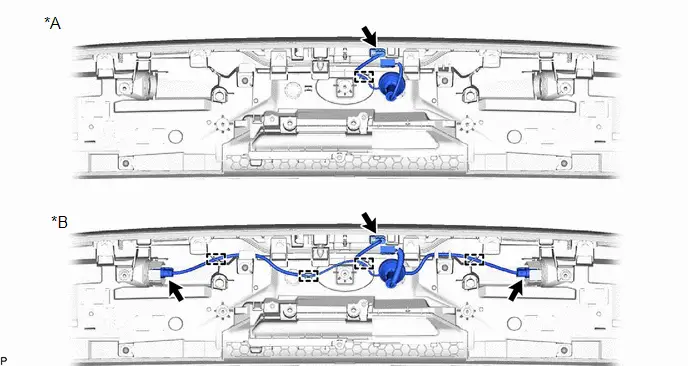
*A |
w/o Tail Light LED |
*B |
w/ Tail Light LED |
3. REMOVE CENTER STOP LIGHT ASSEMBLY
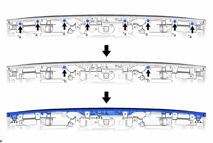
*a |
Screw |
*b |
Grommet |
Inspection
INSPECTION
PROCEDURE
1. INSPECT CENTER STOP LIGHT ASSEMBLY
(a) Illumination Inspection
(1) Apply auxiliary battery voltage to the center stop light assembly and check that the light illuminates. OK:
If the result is not as specified, replace the center stop light assembly. |
|
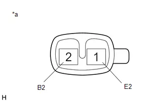
2. INSPECT CENTER STOP LIGHT CORD ASSEMBLY
(a) Measure the resistance according to the value(s) in the table below.
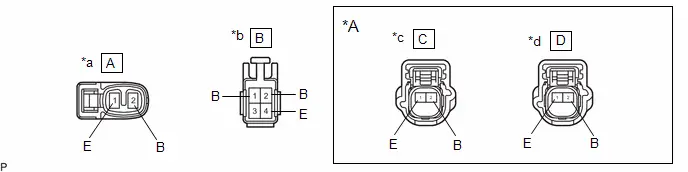
*A |
w/ Tail Light LED |
- |
- |
*a |
Component without harness connected (to Center Stop Light Assembly) |
*b |
Component without harness connected (to Wire Harness) |
*c |
Component without harness connected (to Tail Light LED LH) |
*d |
Component without harness connected (to Tail Light LED RH) |
(1) Inspect the center stop light circuit.
Standard Resistance:
Tester Connection | Condition | Specified Condition | Result |
|---|---|---|---|
A-1 - B-4 |
Always |
Below 1 Ω |
Ω |
A-2 - B-2 |
Always |
Below 1 Ω |
Ω |
If the result is not as specified, replace the center stop light cord.
(2) w/ Tail Light LED:
Inspect the tail light circuit.
Standard Resistance:
Tester Connection | Condition | Specified Condition | Result |
|---|---|---|---|
B-1 - C-2 |
Always |
Below 1 Ω |
Ω |
B-1 - D-2 |
Always |
Below 1 Ω |
Ω |
B-4 - C-1 |
Always |
Below 1 Ω |
Ω |
B-4 - D-1 |
Always |
Below 1 Ω |
Ω |
If the result is not as specified, replace the center stop light cord.
Installation
INSTALLATION
COMPONENTS (INSTALLATION)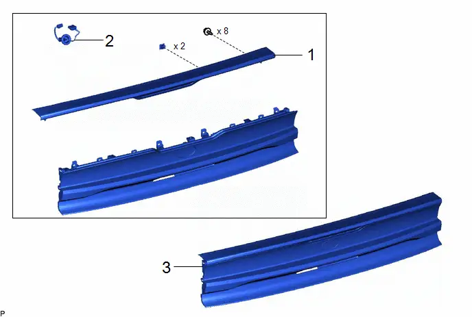
Procedure | Part Name Code |  |  |  |
|
|---|---|---|---|---|---|
1 |
CENTER STOP LIGHT ASSEMBLY |
81570 |
- |
- |
- |
2 |
CENTER STOP LIGHT CORD ASSEMBLY |
81935D |
- |
- |
- |
3 |
REAR LIGHT ASSEMBLY |
- |
- |
- |
- |
*a |
The illustration shown is an example only. The illustration may differ from the actual parts according to the model. |
- |
- |
PROCEDURE
1. INSTALL CENTER STOP LIGHT ASSEMBLY
2. INSTALL CENTER STOP LIGHT CORD ASSEMBLY
3. INSTALL REAR LIGHT ASSEMBLY
Click here 