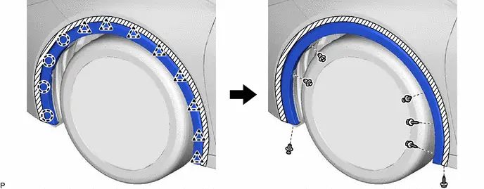
Wheel Opening Moulding (for Front Side)
- Removal
- Disassembly
- Reassembly
- Installation
Removal
REMOVAL
HINT:
- Use the same procedure for the RH side and LH side.
- The following procedure is for the LH side.
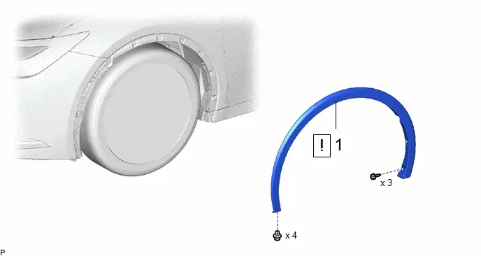
Procedure | Part Name Code |  |  |  |
|
|---|---|---|---|---|---|
1 |
FRONT FENDER MOULDING SUB-ASSEMBLY |
75602A |
 |
- |
- |
PROCEDURE
1. REMOVE FRONT FENDER MOULDING SUB-ASSEMBLY
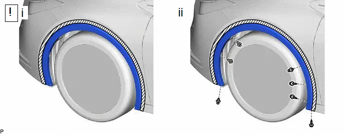
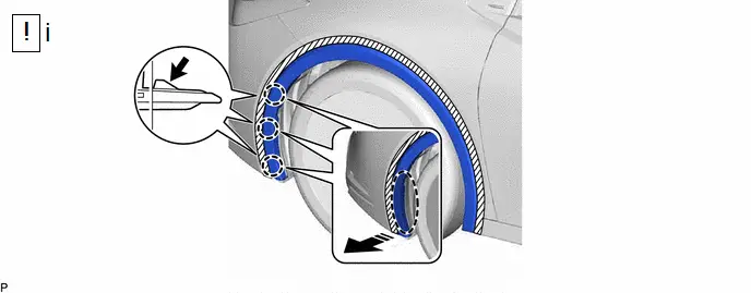
(1) Apply protective tape around the front fender moulding sub-assembly as shown in the illustration.
(2) Remove the 4 clips and 3 screws.
 |
Push |
 |
Place Hand Here |
 |
Remove in this Direction |
- |
- |
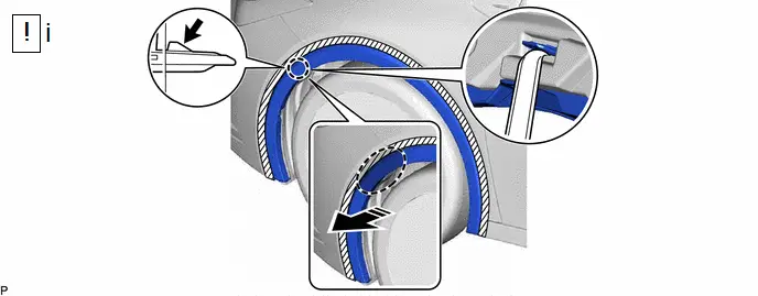
(1) Using a moulding remover, disengage the claw by pushing the area indicated by the arrow in the illustration.
NOTICE:
To avoid damaging the claw, do not forcibly pull the front fender moulding sub-assembly.
 |
Push |
 |
Place Hand Here |
 |
Remove in this Direction |
- |
- |
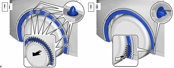
(1) Disengage the 3 claws by pushing the area indicated by the arrow in the illustration with a finger.
NOTICE:
To avoid damaging the claw, do not forcibly pull the front fender moulding sub-assembly.
 |
Place Hand Here |
 |
Remove in this Direction (1) |
 |
Remove in this Direction (2) |
- |
- |
(1) Disengage the 7 clips as shown in the illustration.
(2) Disengage the clip as shown in the illustration to remove the front fender moulding sub-assembly.
NOTICE:
To prevent damage to the clips, make sure to pull the front fender moulding sub-assembly evenly and straight.
Disassembly
DISASSEMBLY
HINT:
- Use the same procedure for the RH side and LH side.
- The following procedure is for the LH side.
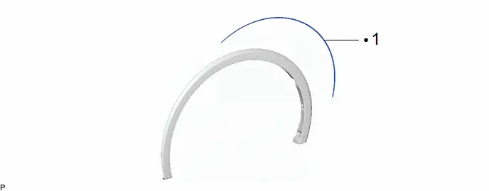
Procedure | Part Name Code |  |  |  |
|
|---|---|---|---|---|---|
1 |
NO. 3 FRONT WHEEL OPENING EXTENSION PAD |
53853 |
- |
- |
- |
● |
Non-reusable part |
- |
- |
PROCEDURE
1. REMOVE NO. 3 FRONT WHEEL OPENING EXTENSION PAD

Reassembly
REASSEMBLY
HINT:
- Use the same procedure for the RH side and LH side.
- The following procedure is for the LH side.
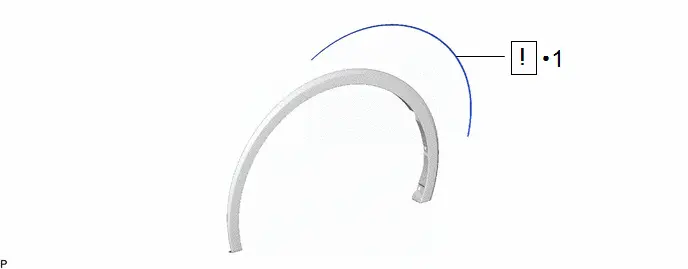
Procedure | Part Name Code |  |  |  |
|
|---|---|---|---|---|---|
1 |
NO. 3 FRONT WHEEL OPENING EXTENSION PAD |
53853 |
 |
- |
- |
● |
Non-reusable part |
- |
- |
PROCEDURE
1. INSTALL NO. 3 FRONT WHEEL OPENING EXTENSION PAD
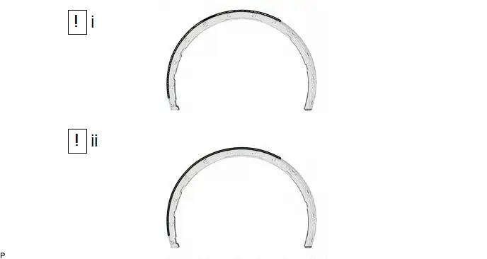
 |
Cleaning Area |
 |
Primer |
(1) Clean the front fender moulding surface.
1. Using a heat light, heat the double-sided tape remaining on the front fender moulding and No. 3 front wheel opening extension pad.
Heating TemperatureArea | Temperature | Area | Temperature |
|---|---|---|---|
Front Fender Moulding |
20 to 30 °C |
No. 3 Front Wheel Opening Extension Pad |
20 to 30 °C |
CAUTION:
- Do not touch the heat light and heated parts, touching the heat light may result in burns.
- Touching heated parts for a long time may result in burns.
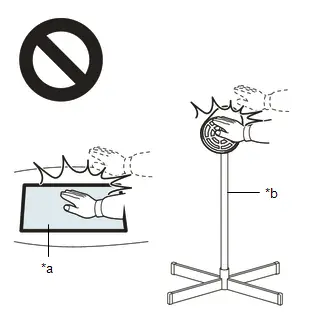
*a |
Heated Part |
*b |
Heat Light |
NOTICE:
Do not heat the front fender moulding excessively.
2. Remove any remaining double-sided tape from the front fender moulding.
3. Wipe off any tape adhesive residue with cleaner.
(2) Apply primer to front fender moulding on the installation area of the No. 3 front wheel opening extension pad.
1. Using a brush or felt, apply primer or equivalent to the No. 3 front wheel opening extension pad installation area.
NOTICE:
- Replace the brush or felt if it is dirty or has become hardened.
- Do not apply primer to the painted side.
- Do not touch the front fender moulding until the primer has dried.
2. Let the primer dry sufficiently.
NOTICE:
Do not touch applied surfaces until the primer is dry.
Recommended drying time:
10 minutes or more (at 23 °C)
3. Confirm that the primer has completely dried by touching the front fender moulding. Then remove the tape.
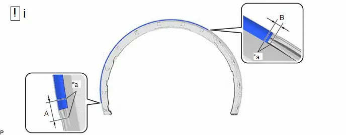
*a |
Scribed Line |
- |
- |
Standard Measurement:
Area | Measurement | Area | Measurement |
|---|---|---|---|
A |
10.0 mm (0.394 in.) |
B |
3.0 mm (0.118 in.) |
(1) Install a new No. 3 front wheel opening extension pad.
1. Using a heat light, heat the front fender moulding surface.
2. Remove the release paper from the No. 3 front wheel opening extension pad.
HINT:
After removing the release paper, keep the exposed adhesive free from foreign matter.
3. Install the No. 3 front wheel opening extension pad as shown in the illustration.
HINT:
- Apply the No. 3 front wheel opening extension pad along the scribed line on the front fender moulding.
- Press the No. 3 front wheel opening extension pad firmly to install it.
Installation
INSTALLATION
HINT:
- Use the same procedure for the RH side and LH side.
- The following procedure is for the LH side.
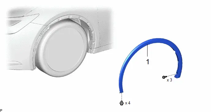
Procedure | Part Name Code |  |  |  |
|
|---|---|---|---|---|---|
1 |
FRONT FENDER MOULDING SUB-ASSEMBLY |
75602A |
- |
- |
- |
PROCEDURE
1. INSTALL FRONT FENDER MOULDING SUB-ASSEMBLY