Evaporator Pipe Temperature Sensor
- Removal
- Inspection
- Installation
Removal
REMOVAL
COMPONENTS (REMOVAL)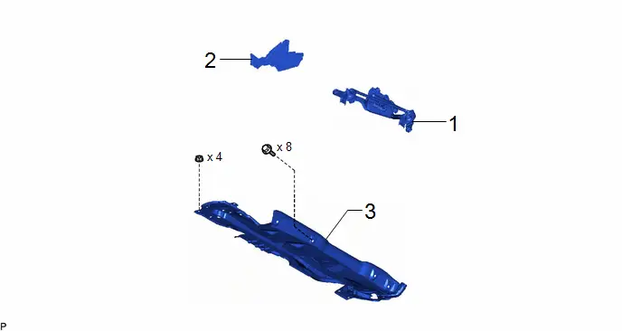
Procedure | Part Name Code |  |  |  |
|
|---|---|---|---|---|---|
1 |
WINDSHIELD WIPER MOTOR AND LINK ASSEMBLY |
- |
- |
- |
- |
2 |
WATER GUARD PLATE |
55734D |
- |
- |
- |
3 |
OUTER COWL TOP PANEL SUB-ASSEMBLY |
55701J |
- |
- |
- |
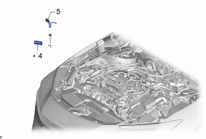
Procedure | Part Name Code |  |  |  |
|
|---|---|---|---|---|---|
4 |
NO. 2 COOLER PACKING |
88E78 |
- |
- |
- |
5 |
NO. 2 AIR CONDITIONING THERMISTOR ASSEMBLY |
88620R |
- |
- |
- |
*1 |
NO. 1 COOLER CLAMP |
- |
- |
● |
Non-reusable part |
- |
- |
PROCEDURE
1. REMOVE WINDSHIELD WIPER MOTOR AND LINK ASSEMBLY
Click here 
2. REMOVE WATER GUARD PLATE
Click here 
3. REMOVE OUTER COWL TOP PANEL SUB-ASSEMBLY
Click here 
4. REMOVE NO. 2 COOLER PACKING

5. REMOVE NO. 2 AIR CONDITIONING THERMISTOR ASSEMBLY


Inspection
INSPECTION
PROCEDURE
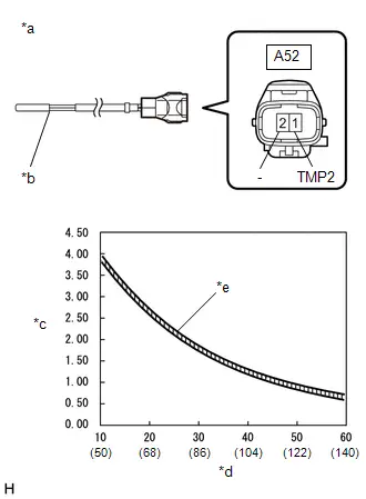
1. INSPECT NO. 2 AIR CONDITIONING THERMISTOR ASSEMBLY
(a) Measure the resistance according to the value(s) in the table below. Standard Resistance:  Click Location & Routing(A52) Click Connector(A52)
NOTICE:
HINT: As the temperature increases, the resistance decreases (see the graph).
|
|
Installation
INSTALLATION
COMPONENTS (INSTALLATION)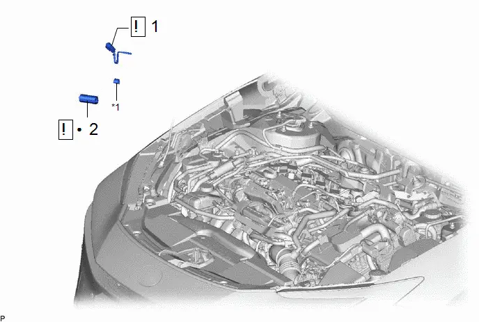
Procedure | Part Name Code |  |  |  |
|
|---|---|---|---|---|---|
1 |
NO. 2 AIR CONDITIONING THERMISTOR ASSEMBLY |
88620R |
 |
- |
- |
2 |
NO. 2 COOLER PACKING |
88E78 |
 |
- |
- |
*1 |
NO. 1 COOLER CLAMP |
- |
- |
● |
Non-reusable part |
- |
- |
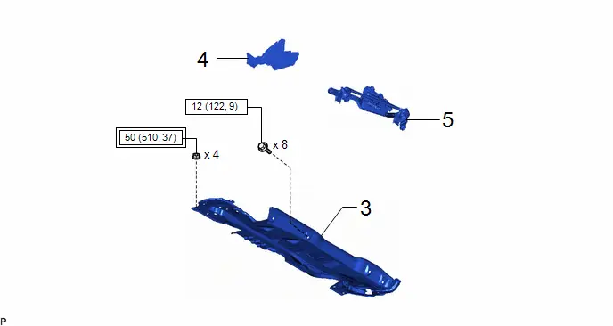
Procedure | Part Name Code |  |  |  |
|
|---|---|---|---|---|---|
3 |
OUTER COWL TOP PANEL SUB-ASSEMBLY |
55701J |
- |
- |
- |
4 |
WATER GUARD PLATE |
55734D |
- |
- |
- |
5 |
WINDSHIELD WIPER MOTOR AND LINK ASSEMBLY |
- |
- |
- |
- |
 |
Tightening torque for "Major areas involving basic Toyota Prius vehicle performance such as moving/turning/stopping": N*m (kgf*cm, ft.*lbf) |
 |
N*m (kgf*cm, ft.*lbf): Specified torque |
PROCEDURE
1. INSTALL NO. 2 AIR CONDITIONING THERMISTOR ASSEMBLY
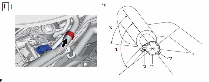
*1 |
NO. 1 SUCTION TUBE |
*2 |
NO. 1 COOLER CLAMP |
*3 |
NO. 2 AIR CONDITIONING THERMISTOR ASSEMBLY |
- |
- |
*a |
View A |
*b |
Installation Angle (90°) |
*c |
Installation Angle (45.6°) |
- |
- |
(1) Install the No. 2 air conditioning thermistor assembly with the No. 1 cooler clamp as shown in the illustration.

(1) Engage the claw.
(2) Connect the connector.
2. INSTALL NO. 2 COOLER PACKING
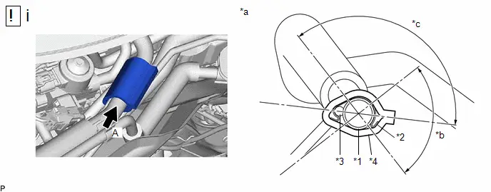
*1 |
NO. 1 SUCTION TUBE |
*2 |
NO. 1 COOLER CLAMP |
*3 |
NO. 2 AIR CONDITIONING THERMISTOR ASSEMBLY |
*4 |
NO. 2 COOLER PACKING |
*a |
View A |
*b |
Installation Angle (90°) |
*c |
Installation Angle (134.4°) |
- |
- |
(1) Perform the following procedure to install the No. 2 cooler packing.
1. Remove any remaining No. 2 cooler packing from the No. 2 air conditioning thermistor and No. 1 suction tube.
2. Remove the release paper from a new No. 2 cooler packing.
3. Install the No. 2 cooler packing as shown in the illustration.
3. INSTALL OUTER COWL TOP PANEL SUB-ASSEMBLY
Click here 
4. INSTALL WATER GUARD PLATE
5. INSTALL WINDSHIELD WIPER MOTOR AND LINK ASSEMBLY
Click here 