Cooling fan control
Cooling fan control : system diagram
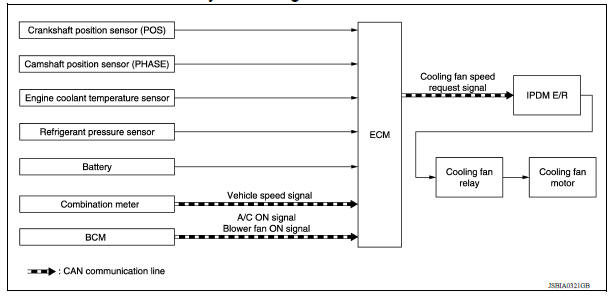
Cooling fan control : system description
INPUT/OUTPUT SIGNAL CHART
| Sensor | Input signal to ECM | ECM function | Actuator |
| Crankshaft position sensor (POS) Camshaft position sensor (PHASE) | Engine speed*1 Piston position | Cooling fan speed request signal | IPDM E/R ↓ Cooling fan relay ↓ Cooling fan motor |
| Engine coolant temperature sensor | Engine coolant temperature | ||
| Battery | Battery voltage*1 | ||
| Refrigerant pressure sensor | Refrigerant pressure | ||
| Combination meter | Vehicle speed signal*2 | ||
| BCM | A/C ON signal*2 Blower fan signal*2 |
*1: The ECM determines the start signal status by the signals of engine speed and battery voltage.
*2: This signal is sent to ECM through CAN communication line.
SYSTEM DESCRIPTION (EXCEPT FOR SINGLE CONNECTOR COOLING FAN WITHOUT A/C)
ECM controls cooling fan speed corresponding to vehicle speed, engine coolant temperature, refrigerant pressure, air conditioner ON signal. Then control system has 3step control [HIGH/LOW/OFF].
Cooling Fan Operation
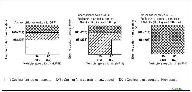
Cooling Fan Relay Operation
The ECM controls cooling fan relays through CAN communication line.
| Cooling fan speed | Cooling fan low relay | Cooling fan high relay | Cooling fan relay |
| Stop (OFF) | OFF | OFF | OFF |
| Low (LOW) | ON | OFF | OFF |
| High (HI) | ON | ON | ON |
SYSTEM DESCRIPTION (FOR SINGLE CONNECTOR COOLING FAN WITHOUT A/C)
ECM controls cooling fan speed corresponding to vehicle speed, engine coolant temperature, refrigerant pressure, air conditioner ON signal. Then control system has 2step control [HIGH/OFF].
Cooling Fan Operation
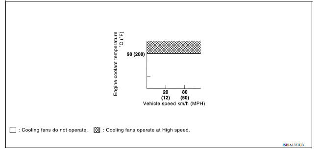
Cooling Fan Relay Operation
The ECM controls cooling fan relays through CAN communication line.
| Cooling fan speed | Cooling fan low relay |
| Stop (OFF) | OFF |
| Operate (HI) | ON |