Front drive shaft
Exploded View
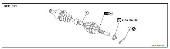
1. Drive shaft 2. Cotter pin A. Apply Molykote M77
Removal and Installation
REMOVAL
- Remove the wheel and tire assembly using power tool. Refer to WT "Adjustment".
- Remove wheel sensor and sensor harness. Refer to BRC "FRONT WHEEL SENSOR : Removal and Installation".
- Remove brake lock plate from strut assembly.
- Remove brake caliper using power tool, leaving brake caliper hydraulic lines connected. Reposition brake caliper aside with wire. Refer to BR "BRAKE CALIPER ASSEMBLY : Exploded View".
NOTE: Avoid depressing brake pedal while brake caliper is removed.
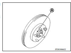
- Put matching marks (A) on disc rotor and wheel hub and bearing assembly, then remove disc rotor.
CAUTION:
- Put matching marks (A) on the wheel hub and the disc rotor before removing the disc rotor.
- Do not drop disc rotor.
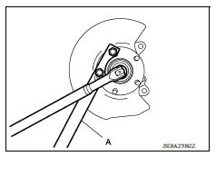
6. Remove and discard cotter pin, and then loosen wheel hub lock nut, using Tool (A).
Tool number : KV40104000 ( - )
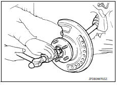
- Separate the drive shaft from the wheel hub and bearing assembly by lightly tapping the end of the drive shaft using a suitable tool and a wood block.
CAUTION:
- Do not place drive shaft joint at an extreme angle. Also be careful not to overextend slide joint.
- Do not allow drive shaft to hang down without support for joint sub-assembly, shaft and the other parts.
NOTE: Use suitable puller, if wheel hub and drive shaft cannot be separated even after performing the above procedure.
- Remove wheel hub lock nut.
- Remove the nuts and bolts, then separate the steering knuckle from strut assembly. Refer to FSU"Removal and Installation".
- Remove drive shaft from wheel hub.
- Use the Tool (A) and a suitable tool (B) while inserting tip of the drive shaft attachment between shaft and transaxle assembly, and then remove drive shaft from transaxle assembly.
Tool number : KV40107500 ( - )
CAUTION:
- Do not place drive shaft joint at an extreme angle when removing drive shaft. Also be careful not to overextend slide joint.
- Confirm that the circular clip is attached to the drive shaft.
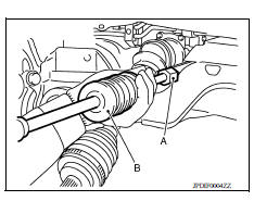
INSTALLATION
Installation is in the reverse order of removal.
Transaxle Side
- Always replace differential side oil seal with new one when installing drive shaft. Refer to TM "Removal and Installation".
- Place the protector (A) onto transaxle assembly to prevent damage to the oil seal while inserting drive shaft. Slide drive shaft sliding joint and tap with a hammer to install securely.
Tool number : KV38107900 ( - )
CAUTION: Check that circular clip is completely engaged.
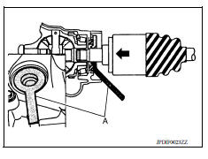
Wheel Hub Side
CAUTION:
- During the installation, do not damage the wheel bearing seal. If damage has occurred, replace wheel bearing with a new one.
- Do not allow paint to adhere to the wheel bearing seal.
- Check each mating surface for water and foreign matter. If there is any water or foreign matter, clean the mating surface.
- Clean the mating surface of wheel hub lock nut and wheel hub.
CAUTION: Do not apply lubricating oil to the mating surface of the wheel hub lock nut and the wheel hub.
- Clean the mating surface of drive shaft, wheel hub, and wheel bearing. And then apply Molykote M77 to surface (A) of joint subassembly of drive shaft.
CAUTION: Apply Molykote M77 to cover entire flat surface of joint subassembly of drive shaft.
Molykote M77 quantity : 1.0 - 3.0 g (0.04 - 0.10 oz)

Perform the final tightening of each of parts under unladen conditions, which were removed when removing wheel hub and axle housing.
When installing a cotter pin, securely bend the end portion to prevent rattles.
CAUTION: Do not reuse cotter pin.