Camshaft valve clearance
In this manual: Camshaft valve clearance
14steps
~84min
3/5difficulty
Done 0 of 14
Inspection and Adjustment
INSPECTION
Perform inspection as follows after removal, replacement or installation of camshaft or valverelated parts, or if there are unusual engine conditions regarding valve clearance.
- Remove rocker cover.
- Measure the valve clearance with the following procedure:
- Set No. 1 cylinder at TDC of its compression stroke.
- Rotate crankshaft pulley (2) clockwise and align TDC mark (no paint) (A) to timing indicator (1) on front cover.
(B) : White paint mark (Not used for service)
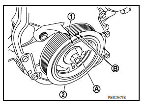
- At the same time, check that both intake and exhaust cam lobes of No. 1 cylinder face inside (
 ) as shown.
(1) : Camshaft (INT)
(2) : Camshaft (EXH)
 : Engine front
- If the lobes do not face inside, rotate the crankshaft pulley 360 degrees to align as shown.

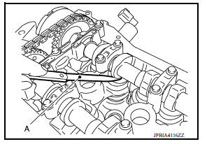
- Use a feeler gauge (A) to measure the clearance between the valve lifter and camshaft.
- Refer to the figure. Using a feeler gauge, measure the valve clearances at locations marked "×" in the table below [also shown with black arrow ( )].
(A) : No. 1 cylinder
(B) : No. 2 cylinder
(C) : No. 3 cylinder
(D) : No. 4 cylinder
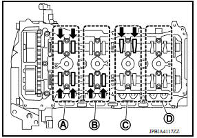
| Measuring position | No. 1 CYL. | No. 2 CYL. | No. 3 CYL. | No. 4 CYL. | |
| No. 1 cylinder at compression TDC | EXH | x | x | ||
| INT | x | x | |||
- Set No. 4 cylinder at TDC of its compression stroke.
- Rotate crankshaft pulley (2) one revolution (360 degrees) and align TDC mark (no paint) (A) to timing indicator (1) on front cover.
(B) : White paint mark (Not use for service)

- Refer to the figure. Using a feeler gauge, measure the valve clearances at locations marked "×" in the table below [also shown with black arrow (
 )].
(A) : No. 1 cylinder
(B) : No. 2 cylinder
(C) : No. 3 cylinder
(D) : No. 4 cylinder

| Measuring position | No. 1 CYL. | No. 2 CYL. | No. 3 CYL. | No. 4 CYL. | |
| No. 4 cylinder at compression TDC | EXH | x | x | ||
| INT | x | x | |||
- If out of the specifications, adjust as necessary. Refer to "ADJUSTMENT".
ADJUSTMENT
NOTE:
Proper valve clearance is obtained by selecting the correct valve lifter head thickness.
- Remove camshaft.
- Remove valve lifters from the locations that are out of specification.
- Measure the center thickness of the removed valve lifters with a micrometer (A).

- Use the equation below to calculate valve lifter thickness for replacement.
Valve lifter thickness calculation: t = t1 + (C1 - C2)
t = Valve lifter thickness to be replaced
t1 = Removed valve lifter thickness
C1 = Measured valve clearance
C2 = Standard valve clearance:
Intake : 0.30 mm (0.012 in)
Exhaust : 0.33 mm (0.013 in)
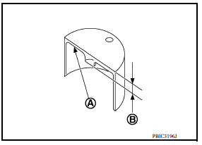
- Thickness of new valve lifter (B) can be identified by stamp mark (A) on the under side of the lifter.
NOTE:
Available thickness of valve lifter: 26 sizes range 3.00 to 3.50 mm (0.1181 to 0.1378 in) in increments of 0.02 mm (0.0008 in) when manufactured at factory.
- Stamp mark "302" indicates 3.02 mm (0.1189 in) in thickness.
- Install the correct thickness valve lifter.
- Install camshaft.
- Install timing chain and related parts.
- Manually rotate crankshaft pulley a few rotations.
- Check that valve clearances are within specification. Refer to "INSPECTION".
- Install remaining parts in the reverse order of removal.
- Warm up the engine, and check for unusual noise and vibration.
Was this page helpful?