Fuel level sensor unit
In this manual: Fuel level sensor unit
~1min read
Disassembly and Assembly
Fuel Level Sender Unit
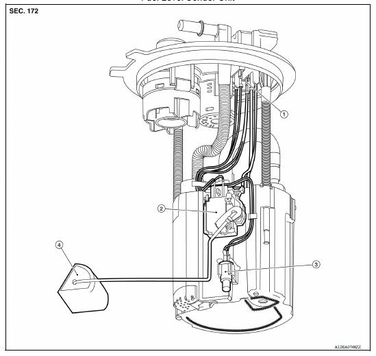
1. Harness connectors 2. Level sending unit module 3. Fuel temperature sensor 4. Float arm assembly
Disassembly
NOTE: Before disassembly, note the proper placement of the wires to the correct terminals and correct wire routing to the terminals.
- Disconnect the red, white, and double black wire connectors.
- Press the tabs on the terminals to release the locking tabs.
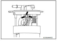
2. Release the two clips and remove the fuel temperature sensor from the pump assembly.
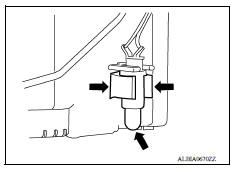
3. Release the tab (A) and slide the level sending unit module and float arm assembly up (B) to remove.

Assembly
Assembly is in the reverse order of disassembly.
NOTE:
- Ensure proper placement of the wires to the correct terminals and correct wire routing to the terminals.
- After connecting terminals, ensure they are securely locked and can not be pulled out.
- When installing the level sending unit, push down until the tab is locked into place.
SERVICE DATA AND SPECIFICATIONS (SDS)
Fuel Tank
STANDARD AND LIMIT
| Fuel tank capacity | Approx. 41.0  (10-7/8 US gal, 9 Imp gal) |
| Fuel recommendation | Refer to GI, "Fuel (Regular Unleaded Gasoline Recommended) HR16DE". |
Was this page helpful?