P1564 ASCD steering switch
DTC Logic
DTC DETECTION LOGIC
NOTE: If DTC P1564 is displayed with DTC P0605, first perform the trouble diagnosis for DTC P0605. Refer to EC, "DTC Logic".
| DTC No. | Trouble diagnosis (Trouble diagnosis content) | DTC detecting condition | Possible cause |
| P1564 | ASCD SW (ASCD steering switch) |
|
|
DTC CONFIRMATION PROCEDURE
1.PRECONDITIONING
If DTC Confirmation Procedure has been previously conducted, always perform the following procedure before conducting the next test.
- Turn ignition switch OFF and wait at least 10 seconds.
- Turn ignition switch ON.
- Turn ignition switch OFF and wait at least 10 seconds.
>> GO TO 2.
2.PERFORM DTC CONFIRMATION PROCEDURE
- Turn ignition switch ON.
- Wait at least 10 seconds.
- Press MAIN switch for at least 10 seconds, then release it and wait at least 10 seconds.
- Press CANCEL switch for at least 10 seconds, then release it and wait at least 10 seconds.
- Press ACCEL/RES switch for at least 10 seconds, then release it and wait at least 10 seconds.
- Press COAST/SET switch for at least 10 seconds, then release it and wait at least 10 seconds.
- Check DTC.
Is DTC detected?
YES >> Proceed to EC, "Diagnosis Procedure".
NO >> INSPECTION END
Diagnosis Procedure
1.CHECK ASCD STEERING SWITCH CIRCUIT
With CONSULT
- Turn ignition switch ON.
- Select "MAIN SW", "CANCEL SW", "RESUME/ACC SW" and "SET SW" in "DATA MONITOR" mode of "ENGINE" using CONSULT.
- Check each item indication as per the following conditions.
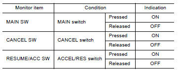

Without CONSULT
- Turn ignition switch ON.
- Check the voltage between ECM harness connector terminals.
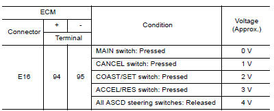
Is the inspection result normal?
YES >> Check intermittent incident. Refer to GI, "Intermittent Incident".
NO >> GO TO 2.
2.CHECK ASCD STEERING SWITCH GROUND CIRCUIT
- Turn ignition switch OFF.
- Disconnect ECM harness connector.
- Disconnect combination switch (spiral cable) harness connector.
- Check the continuity between combination switch (spiral cable) and ECM harness connector.
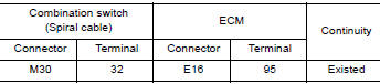
- Also check harness for short to ground and to power.
Is the inspection result normal?
YES >> GO TO 3.
NO >> Repair or replace error-detected parts.
3.CHECK ASCD STEERING SWITCH INPUT SIGNAL CIRCUIT
- Check the continuity between ECM harness connector and combination switch.
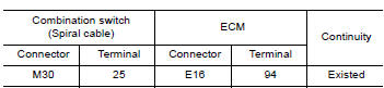
- Also check harness for short to ground and to power.
Is the inspection result normal?
YES >> GO TO 4.
NO >> Repair or replace error-detected parts.
4.CHECK ASCD STEERING SWITCH
Refer to EC, "Component Inspection".
Is the inspection result normal?
YES >> Check intermittent incident. Refer to GI, "Intermittent Incident".
NO >> Replace ASCD steering switch. Refer to ST, "Removal and Installation".
Component Inspection
1.CHECK ASCD STEERING SWITCH
- Disconnect combination switch (spiral cable) harness connector.
- Check the resistance between combination switch harness connector terminals as per the following conditions.
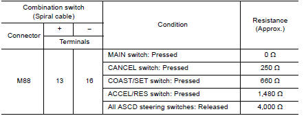
Is the inspection result normal?
YES >> INSPECTION END
NO >> Replace ASCD steering switch. Refer to ST, "Removal and Installation".