P0130 A/F sensor 1
DTC Logic
DTC DETECTION LOGIC
To judge malfunctions, the diagnosis checks that the A/F signal computed by ECM from the A/F sensor 1 signal fluctuates according to fuel feedback control.
| DTC No. | Trouble diagnosis name | DTC detecting condition | Possible cause |
| P0130 | Air fuel ratio (A/F) sensor 1 circuit | The A/F signal computed by ECM from the A/F sensor 1 signal is constantly approx. 2.2 V. |
|
DTC CONFIRMATION PROCEDURE
1.PRECONDITIONING
If DTC Confirmation Procedure has been previously conducted, always perform the following procedure before conducting the next test.
- Turn ignition switch OFF and wait at least 10 seconds.
- Turn ignition switch ON.
- Turn ignition switch OFF and wait at least 10 seconds.
TESTING CONDITION: Before performing the following procedure, confirm that battery voltage is more than 11 V at idle.
Do you have CONSULT?
YES >> GO TO 2.
NO >> GO TO 6.
2.CHECK AIR FUEL RATIO (A/F) SENSOR 1 FUNCTION
- Start engine and warm it up to normal operating temperature.
- Select "ENGINE" using CONSULT.
- Select "A/F SEN1 (B1)" in "DATA MONITOR" mode.
- Check "A/F SEN1 (B1)" indication.
Does the indication fluctuate around 2.2 V?
YES >> GO TO 3.
NO >> Go to EC, "Diagnosis Procedure".
3.PERFORM DTC CONFIRMATION PROCEDURE FOR MALFUNCTION I
- Select "ENGINE" using CONSULT.
- Select "A/F SEN1 (B1) P1276" (for DTC P0130) of "A/F SEN1" in "DTC WORK SUPPORT" mode.
- Touch "START".
- When the following conditions are met, "TESTING" will be displayed on the CONSULT screen.
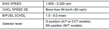
If "TESTING" is not displayed after 20 seconds, retry from step 2.
CAUTION: Always drive vehicle at a safe speed.
Is "TESTING" displayed on CONSULT screen?
YES >> GO TO 4.
NO >> Check A/F sensor 1 function again. GO TO 2.
4.PERFORM DTC CONFIRMATION PROCEDURE FOR MALFUNCTION II
Release accelerator pedal fully.
NOTE: Never apply brake when releasing the accelerator pedal.
Which does "TESTING" change to?
COMPLETED>>GO TO 5.
OUT OF CONDITION>>Retry DTC CONFIRMATION PROCEDURE. GO TO 3.
5.PERFORM DTC CONFIRMATION PROCEDURE FOR MALFUNCTION III
Touch "SELFDIAG RESULT".
Which is displayed on CONSULT screen?
OK >> INSPECTION END
NG >> Go to EC, "Diagnosis Procedure".
6.PERFORM COMPONENT FUNCTION CHECK FOR MALFUNCTION
Perform component function check. Refer to EC, "Component Function Check".
NOTE: Use component function check to check the overall function of the A/F sensor 1 circuit. During this check, a 1st trip DTC might not be confirmed.
Is the inspection result normal?
YES >> INSPECTION END
NO >> Go to EC, "Diagnosis Procedure".
Component Function Check
1.PERFORM COMPONENT FUNCTION CHECK
 With GST
- Start engine and warm it up to normal operating temperature.
- Drive the vehicle at a speed of 80 km/h for a few minutes in the suitable gear position.
- Shift the selector lever to D position (A/T or CVT) or 5th position (M/T), then release the accelerator pedal fully until the vehicle speed decreases to 50 km/h.
CAUTION: Always drive vehicle at a safe speed.
NOTE: Never apply brake when releasing the accelerator pedal.
- Repeat steps 2 and 3 for five times.
- Stop the vehicle and turn ignition switch OFF.
- Turn ignition switch ON.
- Turn ignition switch OFF and wait at least 10 seconds.
- Restart engine.
- Repeat steps 2 and 3 for five times.
- Stop the vehicle and connect GST to the vehicle.
- Check 1st trip DTC.
Is 1st trip DTC detected?
YES >> Go to EC, "Diagnosis Procedure".
NO >> INSPECTION END
Diagnosis Procedure
1.CHECK GROUND CONNECTION
- Turn ignition switch OFF.
- Check ground connection E. Refer to Ground Inspection in GI, "Circuit Inspection".
Is the inspection result normal?
YES >> GO TO 2.
NO >> Repair or replace ground connection.
2.CHECK AIR FUEL RATIO (A/F) SENSOR 1 POWER SUPPLY CIRCUIT
- Disconnect A/F sensor 1 harness connector.
- Turn ignition switch ON.
- Check the voltage between A/F sensor 1 harness connector and ground.

Is the inspection result normal?
YES >> GO TO 4.
NO >> GO TO 3.
3.DETECT MALFUNCTIONING PART
Check the following.
- IPDM E/R harness connector F42
- 20A fuse (No. 53)
- Harness for open or short between A/F sensor 1 and fuse
>> Repair or replace harness or connectors.
4.CHECK A/F SENSOR 1 INPUT SIGNAL CIRCUIT FOR OPEN AND SHORT
- Turn ignition switch OFF.
- Disconnect ECM harness connector.
- Check the continuity between A/F sensor 1 harness connector and ECM harness connector.

4. Check the continuity between A/F sensor 1 harness connector and ground or ECM harness connector and ground.
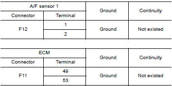
5. Also check harness for short to power.
Is the inspection result normal?
YES >> GO TO 5.
NO >> Repair open circuit, short to ground or short to power in harness or connectors.
5.CHECK INTERMITTENT INCIDENT
Perform GI, "Intermittent Incident".
Is the inspection result normal?
YES >> GO TO 6.
NO >> Repair or replace.
6.REPLACE AIR FUEL RATIO (A/F) SENSOR 1
Replace malfunctioning air fuel ratio (A/F) sensor 1. Refer to EM, "Exploded View".
CAUTION:
- Discard any A/F sensor which has been dropped from a height of more than 0.5 m (19.7 in) onto a hard surface such as a concrete floor; use a new one.
- Before installing new A/F sensor, clean exhaust system threads using Oxygen Sensor Thread Cleaner [commercial service tool (J4389718 or J4389712)] and approved antiseize lubricant (commercial service tool).
>> INSPECTION END