Cylinder block

In this manual: Cylinder block
Precautions — 1Preparation — 1Camshaft valve clearance — 1Compression pressure — 1Noise, vibration and harshness (NVH) troubleshooting — 1Drive belt — 1Air cleaner filter — 1Spark plug — 1Drive belt idler pulley — 1Air cleaner and air duct — 1Intake manifold — 1Exhaust manifold — 1Oil pan (lower) — 1Fuel injector and fuel tube — 1Ignition coil, spark plug and rocker cover — 1Timing chain — 1Camshaft — 1Valve oil seal — 1Front oil seal — 1Rear oil seal — 1Cylinder head — 1Engine assembly — 1Engine stand setting — 1Oil pan (upper) and oil strainer — 1Cylinder block — 1How to select piston and bearing — 1Service data and specifications (sds) — 1Precautions — 1Preparation — 1Engine oil — 1Oil filter — 1Oil pump — 1Oil cooler — 1Service data and specifications (SDS) — 1Precaution — 1Description — 1Engine coolant — 1Radiator — 1Cooling fan — 1Water pump — 1Thermostat — 1Water outlet — 1Precaution — 1Engine control system — 1Structure and operation — 1Engine control system — 1Multiport fuel injection system — 1Electric ignition system — 1Air conditioning cut control — 1Cooling fan control — 1Evaporative emission system — 1Intake valve timing control — 1Exhaust valve timing control — 1Engine protection control at low engine oil pressure — 1Fuel filler cap warning system — 1Automatic speed control device (ASCD) — 1Automatic speed control device (ASCD) — 1Diagnosis description — 1Ecm — 1Diagnosis and repair workflow — 1Additional service when replacing ECM — 1Accelerator pedal released position learning — 1Throttle valve closed position learning — 1Idle air volume learning — 1Mixture ratio selflearning value clear — 1Basic inspection — 1Fuel pressure check — 1How to set SRT code — 1How to erase permanent DTC — 1Trouble diagnosis specification value — 1Power supply and ground circuit — 1U0101 can comm circuit — 1U1001 CAN comm circuit — 1P0011 IVT control — 1P0014 EVT control — 1P0031, P0032 A/F sensor 1 heater — 1P0037, P0038 HO2s2 heater — 1P0075 IVT control solenoid valve — 1P0078 EVT control solenoid valve — 1P0101 MAF sensor — 1P0102, P0103 MAF sensor — 1P0111 IAT sensor — 1P0112, P0113 IAT sensor — 1P0116 ECT sensor — 1P0117, P0118 ECT sensor — 1P0122, P0123 TP sensor — 1P0125 ECT sensor — 1P0127 IAT sensor — 1P0128 thermostat function — 1P0130 A/F sensor 1 — 1P0131 A/F sensor 1 — 1P0132 A/F sensor 1 — 1P0137 HO2s2 — 1P0138 HO2s2 — 1P0139 HO2s2 — 1P014C, P014D, P015A, P015B, A/F sensor 1 — 1P0171 fuel injection system function — 1P0181 FTT sensor — 1P0182, P0183 FTT sensor — 1P0196 EOT sensor — 1P0197, P0198 EOT sensor — 1P0222, P0223 TP sensor — 1P0300, P0301, P0302, P0303, P0304 misfire — 1P0327, P0328 KS — 1P0335 CKP sensor (POC) — 1P0340 CMP sensor (PHASE) — 1P0420 three way catalyst function — 1P0441 EVAP control system — 1P0443 EVAP canister purge volume control solenoid valve — 1P0444, P0445 EVAP canister purge volume control solenoid valve — 1P0447 EVAP canister vent control valve — 1P0448 EVAP canister vent control valve — 1P0451 EVAP control system pressure sensor — 1P0452 EVAP control system pressure sensor — 1P0453 EVAP control system pressure sensor — 1P0456 EVAP control system — 1P0460 fuel level sensor — 1P0461 fuel level sensor — 1P0462, P0463 fuel level sensor — 1P0500 VSS — 1P0506 ISC system — 1P0507 ISC system — 1P050a, P050b, P050e cold start control — 1P0520 EOP sensor — 1P0524 engine oil pressure — 1P0603 ECM power supply — 1P0605 ECM — 1P0607 ECM — 1P0643 sensor power supply — 1P0850 PNP switch — 1P1078 EVT control position sensor — 1P1148 closed loop control — 1P117A air fuel ratio — 1P1212 TCS communication line — 1P1217 engine over temperature — 1P1225 TP sensor — 1P1226 TP sensor — 1P1550 battery current sensor — 1P1551, P1552 battery current sensor — 1P1553 battery current sensor — 1P1554 battery current sensor — 1P1564 ASCD steering switch — 1P1572 ASCD brake switch — 1P1574 ASCD vehicle speed sensor — 1P1715 Input speed sensor — 1P1720 VSS — 1P1805 brake switch — 1P2096, P2097 A/F sensor 1 — 1P2100, P2103 throttle control motor relay — 1P2101 electric throttle control function — 1P2118 throttle control motor — 1P2119 electric throttle control actuator — 1P2122, P2123 APP sensor — 1P2127, P2128 APP sensor — 1P2135 TP sensor — 1P2138 APP sensor — 1Brake pedal position switch — 1Clutch pedal position switch — 1Cooling fan — 1Electrical load signal — 1Fuel injector — 1Fuel pump — 1Ignition signal — 1Malfunction indicator lamp — 1On board refueling vapor recovery (ORVR) — 1Refrigerant pressure sensor — 1Engine control system symptoms — 1Normal operating condition — 1IDLE SPEED — 1Ignition timing — 1Evaporative emission system — 1EVAP leak check — 1Positive crankcase ventilation — 1Removal and installation — 1Service data and specifications (SDS) — 1Precautions — 1Fuel level sensor unit, fuel filter and fuel pump assembly — 1Fuel tank — 1EVAP canister — 1EVAP canister filter — 1EVAP canister vent control valve — 1EVAP control system pressure sensor — 1Fuel level sensor unit — 1Precautions — 1Exhaust system — 1Precautions — 1Diagnosis and repair workflow — 1B terminal circuit — 1S connector circuit — 1Starter motor — 1Precautions — 1Accelerator control system — 1Precautions — 1Clutch pedal — 1Clutch fluid — 1Clutch pedal — 1Clutch master cylinder — 1Clutch piping — 1CSC (Concentric slave cylinder) — 1Clutch disc and clutch cover — 1Service data and specifications (SDS) — 1Precautions — 1Structure and operation — 1Position switch — 1Gear oil — 1Side oil seal — 1Position switch — 1Control linkage — 1Air breather hose — 15Th main gear assembly — 1Transaxle assembly — 1Transaxle assembly — 1Input shaft and gear — 1Mainshaft and gear — 1Final drive — 1Precautions — 1A/T Control system — 1A/T Shift lock system — 1Transaxle — 1A/T control system — 1Line pressure control — 1Shift change control — 1Lock-up control — 1Diagnosis description — 1Consult function — 1TCM — 1Diagnosis and repair work flow — 1Additional service when replacing TCM — 1Additional service when replacing transaxle assembly — 1A/T Fluid cooler — 1Stall test — 1Line pressure test — 1U0073 Communication bus a off — 1U0100 Lost communication (ECM A) — 1U0140 Lost communication (BCM) — 1U0155 Lost communication (IPC) — 1U0300 Can communication data — 1U1000 Can comm circuit — 1U1117 Lost communication (ABS) — 1P062F EEPROM — 1P0705 Transmission range switch A — 1P0706 Transmission range sensor A — 1P0711 Transmission fluid temperature sensor A — 1P0712 Transmission fluid temperature sensor A — 1P0713 Transmission fluid temperature sensor A — 1P0717 Input speed sensor A — 1P0720 Output speed sensor — 1P072C Stuck in 1GR — 1P072D Stuck in 2GR — 1P072E Stuck in 3GR — 1P072F Stuck in 4GR — 1P0731 1GR Incorrect ratio — 1P0732 2GR Incorrect ratio — 1P0733 3GR Incorrect ratio — 1P0734 4GR Incorrect ratio — 1P073E Unable to engage r range — 1P073F Unable to engage 1GR — 1P0740 Torque converter — 1P0743 Torque converter — 1P0744 Torque converter — 1P074A Unable to engage 2GR — 1P074B Unable to engage 3GR — 1P074C Unable to engage 4GR — 1P0863 TCM Communication — 1P0890 TCM — 1P0962 Pressure control solenoid A — 1P0963 Pressure control solenoid A — 1P0973 Shift solenoid A — 1P0974 Shift solenoid A — 1P0976 Shift solenoid B — 1P0977 Shift solenoid B — 1P0979 Shift solenoid C — 1P0980 Shift solenoid C — 1P0982 Shift solenoid D — 1P0983 Shift solenoid D — 1P2760 Torque converter — 1Main power supply and ground circuit — 1Overdrive control switch — 1O/D OFF indicator lamp — 1Shift position indicator circuit — 1Shift lock system — 1A/T Fluid — 1A/T Shift selector — 1Control cable — 1Key interlock cable — 1TCM — 1Oil pan — 1Output speed sensor — 1Differential side oil seal — 1Fluid cooler tube — 1Transmission assembly — 1Service data and specifications (SDS) — 1Precautions — 1Component parts — 1Shift lock system — 1Structure and operation — 1Fluid cooler & fluid warmer system — 1CVT Control system — 1Line pressure control — 1Shift control — 1Lock-up control — 1Idle neutral control — 1Diagnosis system (TCM) — 1TCM — 1Diagnosis and repair work flow — 1Additional service when replacing TCM — 1Additional service when replacing transaxle assembly — 1Calibration of G Sensor — 1CVT Fluid cooler system — 1Stall test — 1Line pressure test — 1U0073 Communication bus A off — 1U0100 Lost communication (ECM A) — 1U0140 Lost communication (BCM) — 1U0141 Lost communication (BCM A) — 1U0155 Lost communication (IPC) — 1U0300 Can communication data — 1U1000 Can COMM circuit — 1U1117 Lost communication (ABS) — 1P062F EEPROM — 1P0705 Transmission range sensor A — 1P0706 Transmission range sensor A — 1P0711 Transmission fluid temperature sensor A — 1P0712 Transmission fluid temperature sensor A — 1P0713 Transmission fluid temperature sensor A — 1P0715 Input speed sensor A — 1P0720 Output speed sensor — 1P0740 Torque converter — 1P0743 Torque converter — 1P0744 Torque converter — 1P0746 Pressure control solenoid A — 1P0846 Transmission fluid pressure SEN/SW B — 1P0847 Transmission fluid pressure SEN/SW B — 1P0848 Transmission fluid pressure SEN/SW B — 1P0863 TCM Communication — 1P0890 TCM — 1P0962 Pressure control solenoid A — 1P0963 Pressure control solenoid A — 1P0965 Pressure control solenoid B — 1P0966 Pressure control solenoid B — 1P0967 Pressure control solenoid B — 1P0998 Shift solenoid F — 1P0999 Shift solenoid F — 1P099B Shift solenoid G — 1P099C Shift solenoid G — 1P1586 G Sensor — 1P1588 G Sensor — 1P2765 Clutch B speed sensor — 1P2857 Clutch A pressure — 1P2858 Clutch B pressure — 1P2859 Clutch A pressure — 1P285A Clutch B pressure — 1Main power supply and ground circuit — 1Overdrive control switch — 1OD OFF indicator lamp — 1Shift position indicator circuit — 1Shift lock system — 1CVT Control system — 1CVT Fluid — 1CVT Shift selector — 1Control cable — 1Key interlock cable — 1TCM — 1Air breather hose — 1G Sensor — 1Oil pan — 1Primary speed sensor — 1Secondary speed sensor — 1Output speed sensor — 1Differential side oil seal — 1Water hose — 1Fluid cooler hose — 1PLUG — 1Transmission assembly — 1Service data and specifications (SDS) — 1Precautions — 1Front wheel hub and knuckle — 1Front wheel hub and knuckle — 1Front drive shaft — 1Front drive shaft — 1Precautions — 1Front suspension assembly — 1Front coil spring and strut — 1Transverse link — 1Front stabilizer — 1Front suspension member — 1Precautions — 1Wheel alignment — 1Rear shock absorber — 1Coil spring — 1Rear suspension beam — 1PRECAUTIONS — 1Component parts — 1Tire pressure monitoring system — 1Air pressure monitor — 1Air pressure monitor — 1Diagnosis and repair work flow — 1Transmitter wake up operation — 1Id registration procedure — 1C1704, C1705, C1706, C1707 Low tire pressure — 1C1708, C1709, C1710, C1711 Transmitter (no data) — 1C1716, C1717, C1718, C1719 Transmitter (pressure data) — 1C1729 Vehicle speed signal — 1Low tire pressure warning lamp — 1Power supply and ground circuit — 1Low tire pressure warning lamp does not turn on — 1Low tire pressure warning lamp does not turn off — 1Low tire pressure warning lamp blinks — 1Road wheel — 1Road wheel tire assembly — 1Transmitter — 1Precautions — 1Brake pedal — 1Brake fluid — 1Brake pad — 1Disc rotor — 1Brake lining — 1Brake drum — 1Brake pedal — 1Front — 1Rear — 1Brake master cylinder — 1Brake booster and check valve — 1Vacuum lines — 1Brake pad — 1Brake caliper assembly — 1Rear drum brake — 1Precautions — 1Parking brake system — 1Parking brake control — 1Precautions — 1Component parts — 1VDC/TCS/ABS — 1Diagnosis system [abs actuator and electric unit (control unit)] — 1ABS Actuator and electric unit (control unit) — 1Diagnosis and repair work flow — 1Adjustment of steering angle sensor neutral position — 1C1101, C1102, C1103, C1104 Wheel sensor — 1C1105, C1106, C1107, C1108 Wheel sensor — 1C1109 Power and ground system — 1C1110, C1153, C1170 ABS Actuator and electric unit (control unit) — 1C1111 Pump motor — 1C1115 ABS Sensor [abnormal signal] — 1C1116 Stop lamp switch — 1C1120, C1122, C1124, C1126 ABS In valve system — 1C1121, C1123, C1125, C1127 ABS Out valve system — 1C1130 Engine signal — 1C1140 Actuator relay system — 1C1142 Press sensor — 1C1143 Steering angle sensor — 1C1144 Incomplete steering angle sensor adjustment — 1C1145, C1146 Yaw rate/side/decel g sensor — 1C1155 BR Fluid level low — 1C1164, C1165, C1166, C1167 CV/SV System — 1U1000 CAN Comm circuit — 1U1002 System comm (CAN) — 1Parking brake switch — 1VDC OFF Switch — 1ABS Warning lamp — 1Brake warning lamp — 1VDC OFF Indicator lamp — 1Slip indicator lamp — 1VDC/TCS/ABS — 1Excessive ABS Function operation frequency — 1Unexpected pedal reaction — 1The braking distance is long — 1Pedal vibration or ABS operation sound occurs — 1Vehicle jerks during VDC/TCS/ABS control — 1Wheel sensor — 1Sensor rotor — 1ABS Actuator and electric unit (control unit) — 1Precautions — 1Steering wheel — 1Steering wheel — 1Steering column — 1Steering shaft — 1Steering gear and linkage — 1Steering gear and linkage — 1Precautions — 1EPS System — 1Diagnosis system (EPS control unit) — 1EPS control unit — 1Diagnosis and repair workflow — 1C1601 Battery power supply — 1C1604 Torque sensor — 1C1606 EPS Motor — 1C1607, C1608 EPS Control unit — 1C1609 Vehicle speed signal — 1C1610 Engine status signal — 1U1000 CAN Comm circuit — 1EPS Warning lamp — 1EPS Warning lamp does not turn OFF — 1Steering wheel turning force is heavy or light — 1Unbalance steering wheel turning force and return between right and left — 1Unbalance steering wheel turning force (torque variation) — 1EPS Control unit — 1Precautions — 1Component inspection — 1Seat belt retractor — 1Precautions — 1Collision diagnosis — 1Driver air bag module — 1Spiral cable — 1Passenger air bag module — 1Side curtain air bag module — 1Side air bag module — 1Crash zone sensor — 1Side air bag (satellite) sensor — 1Diagnosis sensor unit — 1Precautions — 1Component parts — 1SRS Air bag system — 1Occupant classification system — 1Seat belt warning lamp system — 1Diagnosis system (air bag) — 1Diagnosis sensor unit — 1Diagnosis and repair work flow — 1Inspection and adjustment — 1B1049 - B1052, B1054 - B1057 Driver airbag module — 1B1065 - B1068, B1070 - B1073 Passenger airbag module — 1B1134 - B1137 Side airbag module LH — 1B1129 - B1132 Side airbag module RH — 1B1150 - B1153 Side curtain air bag module LH — 1B1145 - B1148 Side curtain air bag module RH — 1B1086 - B1089 Seat belt pre-tensioner LH — 1B1081 - B1084 Seat belt pre-tensioner RH — 1B1033 - B1035 Crash zone sensor — 1B1118 - B1120 Satellite sensor LH — 1B1113 - B1115 Satellite sensor RH — 1B1343 - B1349 Front door satellite sensor LH — 1B1336 - B1342 Front door satellite sensor RH — 1B1350 Front door satellite sensors — 1B1XXX Air bag diagnosis sensor unit — 1B1023 Passenger air bag off indicator — 1B1017, B1018, B1020, B1021, B1022, B1025, B1032, B1048 OCS System — 1B1209 - B1210 Collision detection — 1SRS Air bag warning lamp does not turn on — 1SRS Air bag warning lamp does not turn off — 1Seat belt warning system — 1Precautions — 1Blower motor — 1Precautions — 1Preparation — 1Component parts — 1Refrigeration system — 1Diagnosis and repair workflow — 1Refrigerant — 1Oil — 1Performance test — 1Compressor — 1Condenser — 1Low-pressure flexible hose — 1High-pressure flexible hose — 1High-pressure pipe — 1Expansion valve — 1Refrigerant pressure sensor — 1A/C Unit assembly — 1Evaporator — 1Precautions — 1Manual air conditioning system — 1Diagnosis and repair workflow — 1Operation inspection — 1A/C On signal — 1Blower fan on signal — 1A/C Indicator — 1Front blower motor — 1Magnet clutch — 1Insufficient cooling — 1Insufficient heating — 1Compressor does not operate — 1Front air control — 1Refrigerant pressure sensor — 1Blower fan resistor — 1Intake door cable — 1Mode door cable — 1Air mix door cable — 1Precautions — 1Squeak and rattle trouble diagnoses — 1Front door finisher — 1Rear door finisher — 1Front pillar finisher — 1Kicking plate inner — 1Dash side finisher — 1Body side welt — 1Center pillar upper finisher — 1Rear pillar finisher — 1Rear parcel shelf finisher — 1Floor trim — 1Headlining — 1Trunk rear plate — 1Trunk lid trim — 1Precautions — 1Squeak and rattle trouble diagnoses — 1Instrument panel assembly — 1Steering column covers — 1Cluster lid A — 1Instrument lower panel LH — 1Glove box assembly and housing — 1Center console assembly — 1Center console lower — 1Center console assembly — 1Precautions — 1Squeak and rattle trouble diagnoses — 1Front seat — 1Passenger side — 1Rear seat — 1Front seat — 1Passenger side — 1Rear seat — 1Door & lock (DLK) — 1Precautions — 1Component parts — 1System (power door lock system) — 1Intelligent key system — 1Door lock function — 1Trunk open function — 1Remote keyless entry function — 1Key reminder function — 1Warning function — 1Diagnosis and repair work flow — 1Inspection and adjustment — 1B2621 Inside antenna — 1B2622 Inside antenna — 1B2623 Inside antenna — 1B2626 Outside antenna — 1B2627 Outside antenna — 1B2628 Outside antenna — 1Power supply and ground circuit — 1Combination meter buzzer — 1Door lock actuator — 1Rear LH — 1Rear RH — 1Door lock and unlock switch — 1Door request switch — 1Door switch — 1Hazard function — 1Intelligent key — 1Key warning lamp — 1Remote keyless entry receiver — 1Shift P Warning lamp — 1Trunk lid opener actuator — 1Trunk lid opener switch — 1Trunk lamp switch — 1Door does not lock/unlock with door lock and unlock switch — 1Door does not lock/unlock with driver side door lock knob or door key cylinder — 1Door does not lock/unlock with door request switch — 1Door does not lock/unlock with intelligent key — 1Trunk lid does not open — 1Ignition position warning function does not operate — 1Auto door lock operation does not operate — 1Vehicle speed sensing auto lock operation does not operate — 1IGN OFF Interlock door unlock function does not operate — 1Hazard and buzzer reminder does not operate — 1Key reminder function does not operate — 1OFF Position warning does not operate — 1P Position warning does not operate — 1ACC Warning does not operate — 1Take away warning does not operate — 1Intelligent key low battery warning does not operate — 1Door lock operation warning does not operate — 1Key id warning does not operate — 1Panic alarm function does not operate — 1Squeak and rattle trouble diagnoses — 1Hood assembly — 1Hood hinge — 1Radiator core support upper — 1Radiator core support lower — 1Front fender — 1Fender cover — 1Door assembly — 1Door hinge — 1Door check link — 1Door assembly — 1Door hinge — 1Door check link — 1Trunk lid assembly — 1Trunk lid striker — 1Trunk lid hinge — 1Torsion bar — 1Trunk lid weather-strip — 1Hood lock — 1Hood lock control cable — 1Hood lock secondary control — 1Door lock — 1Inside handle — 1Outside handle — 1Door lock — 1Inside handle — 1Outside handle — 1Trunk lid lock — 1Trunk lid opener handle — 1Trunk lid opener cable — 1Fuel filler opener cable — 1Fuel filler lid lock — 1Door switch — 1Inside key antenna — 1Outside key antenna — 1Intelligent key battery — 1Precautions — 1Component parts — 1Automatic door lock/unlock function — 1Power door lock system — 1Remote keyless entry system — 1Trunk lid opener system — 1Diagnosis system (BCM) — 1Diagnosis and repair workflow — 1U1000 CAN COMM — 1Power supply and ground circuit — 1Door switch — 1Door lock and unlock switch — 1Key cylinder switch — 1Key switch (BCM Input) — 1Door lock actuator — 1Trunk lid opener actuator — 1Remote keyless entry receiver — 1Keyfob battery and function — 1Horn function — 1Warning chime function — 1Hazard function — 1Keyfob ID set up with consult — 1Keyfob ID set up without consult — 1Power door lock system symptoms — 1Squeak and rattle trouble diagnoses — 1Hood assembly — 1Hood hinge — 1Radiator core support upper — 1Radiator core support lower — 1Front fender — 1Fender cover — 1Door assembly — 1Door hinge — 1Door check link — 1Door assembly — 1Door hinge — 1Door check link — 1Trunk lid assembly — 1Trunk lid striker — 1Trunk lid hinge — 1Torsion bar — 1Trunk lid weather-strip — 1Hood lock — 1Hood lock control cable — 1Hood lock bell crank — 1Door lock — 1Inside handle — 1Outside handle — 1Door lock — 1Inside handle — 1Outside handle — 1Trunk lid lock — 1Trunk lid opener handle — 1Trunk lid opener cable — 1Fuel filler lid — 1Fuel filler opener cable — 1Fuel filler lid lock — 1Door switch — 1Remote keyless entry receiver — 1Keyfob battery — 1Security control system (SEC) — 1Precautions — 1Component parts Component parts Component parts — 1Intelligent key system/engine start function — 1Nissan anti-theft system — 1Vehicle security system — 1Diagnosis system (BCM) — 1Diagnosis and repair work flow — 1Additional service when replacing control unit — 1P1610 Lock mode — 1P1611 ID Discord, IMMU-ECM — 1P1612 Chain of ECM-IMMU — 1B2192 ID discord, IMMU-ECM — 1B2193 Chain of ECM-IMMU — 1B2195 Anti-scanning — 1B2196 Dongle unit — 1B2198 NATS antenna AMP — 1B2555 Stop lamp — 1B2556 Push-button ignition switch — 1B2557 Vehicle speed — 1B2601 Shift position — 1B2602 Shift position — 1B2603 Shift position — 1B2604 Shift position — 1B2605 Shift position — 1B2608 Starter relay — 1B260F Engine status — 1B26F3 Starter control relay — 1B26F4 Starter control relay — 1B26F7 BCM — 1B26FC Key registration — 1B210B Starter control relay — 1B210C Starter control relay — 1B210D Starter relay — 1B210E Starter relay — 1B210F Shift position/clutch interlock switch — 1B2110 Shift position/clutch interlock switch — 1Engine does not start when intelligent key is inside of vehicle — 1Security indicator lamp does not turn on or blink — 1NATS antenna AMP — 1Push-button ignition switch — 1Remote keyless entry receiver — 1Precautions — 1Nissan vehicle immobilizer system-NATS — 1Diagnosis system (IPDM E/R) — 1Diagnosis and repair workflow — 1Inspection and adjustment — 1U1000 CAN Comm — 1U1010 Control unit (CAN) — 1P1610 Lock mode — 1B2190, P1614 NATS antenna AMP — 1B2191, P1615 Difference of key — 1B2192, P1611 ID discord, IMMU-ECM — 1B2193, P1612 Chain of ECM-IMMU — 1B2195 Anti-scanning — 1B2196 Dongle unit — 1Power supply and ground circuit — 1Vehicle security indicator — 1Nissan vehicle immobilizer systemnats symptoms — 1NATS antenna AMP — 1Precautions — 1Squeak and rattle trouble diagnoses — 1Windshield glass — 1Rear window glass — 1Front door glass — 1Front regulator — 1Rear door glass — 1Rear regulator — 1Precautions — 1System — 1Diagnosis and repair work flow — 1Power supply and ground circuit — 1Front power window switch (passenger side) — 1Rear power window switch — 1Power window motor — 1Door switch — 1None of the power windows can be operated using any switch — 1Driver side power window does not operate — 1Front passenger side power window does not operate — 1Rear LH side power window does not operate — 1Rear RH side power window does not operate — 1Power window main switch — 1Front power window switch — 1Rear power window switch — 1Precautions — 1Squeak and rattle trouble diagnoses — 1Front bumper — 1Under cover — 1Rear bumper — 1Front grille — 1Cowl top — 1Fender protector — 1Roof side molding — 1Door outside molding — 1Trunk lid finisher — 1Door parting seal — 1Rear spoiler — 1Body repair (BRM) — 1Precautions — 1Precautions in repairing high strength steel — 1Repairing material — 1Corrosion protection — 1Replacement operations — 1Body alignment — 1Precautions — 1Door mirror remote control switch (mirror switch/changeover switch) — 1Squeak and rattle trouble diagnoses — 1Inside mirror — 1Door mirror assembly — 1Front door corner finisher — 1Door mirror glass — 1Door mirror rear finisher — 1Door mirror remote control switch — 1Precautions — 1Headlamp system — 1With daytime light system — 1Front fog lamp system — 1Turn signal and hazard warning lamp system — 1Parking, license plate and tail lamp system — 1Diagnosis system (IPDM E/R) (with intelligent key system) — 1Diagnosis system (IPDM E/R) (without intelligent key system) — 1Diagnosis and repair workflow — 1Power supply and ground circuit — 1Headlamp (HI) circuit — 1Headlamp (LO) circuit — 1Parking lamp circuit — 1Turn signal lamp circuit — 1Front fog lamp circuit — 1Both side headlamps do not switch to high beam — 1Both side headlamps (LO) are not turned on — 1Parking, license plate and tail lamps are not turned on — 1Both side front fog lamps are not turned on — 1Headlamp aiming adjustment — 1Front fog lamp aiming adjustment — 1Front combination lamp — 1Front fog lamp — 1Combination switch — 1Hazard switch — 1Rear combination lamp — 1High-mounted stop lamp — 1License plate lamp — 1Precautions — 1System — 1Diagnosis and repair workflow — 1Power supply and ground circuit — 1Battery saver output/power supply circuit — 1Interior room lamp control circuit — 1Trunk room lamp circuit — 1Push-button ignition switch illumination circuit — 1Map lamp — 1Interior room lamp — 1Console lamp — 1Trunk room lamp — 1Precautions — 1System — 1Diagnosis system (IPDM E/R) (With intelligent key system) — 1Diagnosis system (IPDM E/R) (Without intelligent key system) — 1Diagnosis and repair workflow — 1Wiper and washer fuse — 1Front wiper motor lo circuit — 1Front wiper motor hi circuit — 1Front wiper auto stop signal circuit — 1Front wiper motor ground circuit — 1Washer motor circuit — 1Washer switch — 1Front wiper does not operate — 1Normal operating condition — 1Wiper arm — 1Wiper blade — 1Wiper refill — 1Wiper drive assembly — 1Washer tank — 1Washer pump — 1Washer nozzle — 1Washer tube — 1Precautions — 1System — 1Diagnosis and repair work flow — 1Rear window defogger switch — 1Rear window defogger relay — 1Rear window defogger power supply and ground circuit — 1Driver side door mirror defogger — 1Passenger side door mirror defogger — 1Rear window defogger and door mirror defogger do not operate — 1Both doors mirror defogger don't operate but rear window defogger operates — 1Filament — 1Precautions — 1Horn — 1Precautions — 1Power socket — 1Body control system (BCS) — 1Precautions — 1System — 1Diagnosis system (BCM) — 1BCM — 1Inspection and adjustment — 1U1000 CAN Comm circuit — 1U1010 Control unit (CAN) — 1U0415 Vehicle speed — 1B2562 Low voltage — 1Power supply and ground circuit — 1Combination switch input circuit — 1Combination switch output circuit — 1BCM (Body control module) — 1Combination switch — 1Precautions — 1System — 1BCM — 1Inspection and adjustment — 1U1000 CAN Comm — 1U1010 Control unit (CAN) — 1Power supply and ground circuit — 1Combination switch input circuit — 1Combination switch output circuit — 1BCM (Body control module) — 1Combination switch — 1LAN System (LAN) — 1Precautions — 1System — 1Trouble diagnosis — 1Diagnosis and repair workflow — 1Precautions — 1CAN Communication system — 1Main line between IPDM-E and DLC circuit — 1ECM Branch line circuit — 1ABS Branch line circuit — 1IPDM-E Branch line circuit — 1TCM Branch line circuit — 1A-BAG Branch line circuit — 1AV Branch line circuit — 1DLC Branch line circuit — 1EPS Branch line circuit — 1M&A Branch line circuit — 1STRG Branch line circuit — 1BCM Branch line circuit — 1CAN Communication circuit — 1Main line between IPDM-E and DLC circuit — 1ECM Branch line circuit — 1ABS Branch line circuit — 1IPDM-E Branch line circuit — 1A-BAG Branch line circuit — 1DLC Branch line circuit — 1EPS Branch line circuit — 1M&A Branch line circuit — 1STRG Branch line circuit — 1BCM Branch line circuit — 1CAN Communication circuit — 1Main line between IPDM-E and DLC circuit — 1ECM Branch line circuit — 1ABS Branch line circuit — 1IPDM-E Branch line circuit — 1TCM Branch line circuit — 1A-BAG Branch line circuit — 1DLC Branch line circuit — 1EPS Branch line circuit — 1M&A Branch line circuit — 1STRG Branch line circuit — 1BCM Branch line circuit — 1CAN Communication circuit — 1Main line between IPDM-E and DLC circuit — 1ECM Branch line circuit — 1ABS Branch line circuit — 1IPDM-E Branch line circuit — 1TCM Branch line circuit — 1A-BAG Branch line circuit — 1DLC Branch line circuit — 1EPS Branch line circuit — 1M&A Branch line circuit — 1STRG Branch line circuit — 1BCM Branch line circuit — 1CAN Communication circuit — 1Main line between IPDM-E and DLC circuit — 1ECM Branch line circuit — 1ABS Branch line circuit — 1IPDM-E Branch line circuit — 1TCM Branch line circuit — 1A-BAG Branch line circuit — 1AV Branch line circuit — 1DLC Branch line circuit — 1EPS Branch line circuit — 1M&A Branch line circuit — 1STRG Branch line circuit — 1BCM Branch line circuit — 1CAN Communication circuit — 1Power control system (PCS) — 1Precautions — 1System — 1Diagnosis system (IPDM E/R) — 1IPDM E/R (Intelligent power distribution module engine room) — 1U1000 CAN Comm circuit — 1B2098 Ignition relay on stuck — 1B2099 Ignition relay off stuck — 1Power supply and ground circuit — 1IPDM E/R — 1Precautions — 1System — 1Diagnosis system (IPDM E/R) — 1IPDM E/R (Intelligent power distribution module engine room) — 1U1000 CAN Comm circuit — 1B2098 Ignition relay on stuck — 1B2099 Ignition relay off stuck — 1Power supply and ground circuit — 1IPDM E/R — 1Precautions — 1Power distribution system — 1Diagnosis and repair work flow — 1U1000 CAN Comm circuit — 1B2614 ACC Relay circuit — 1B2615 Blower relay circuit — 1B2616 Ignition relay circuit — 1B2618 BCM — 1B261A Push-button ignition switch — 1B26F1 Ignition relay — 1B26F2 Ignition relay — 1B26F6 BCM — 1Push-button ignition switch — 1Push-button ignition switch does not operate — 1Push-button ignition switch — 1Precautions — 1System — 1Diagnosis and repair workflow — 1Charging system preliminary inspection — 1Power generation voltage variable control system operation inspection — 1B Terminal circuit — 1L Terminal circuit (open) — 1L Terminal circuit (short) — 1S Terminal circuit — 1Generator — 1Precautions — 1Battery — 1Power supply routing circuit — 1Harness — 1Harness connector — 1Battery — 1Meter, warning lamp & indicator (MWI) — 1Precautions — 1System — 1Diagnosis system (combination meter) — 1Diagnosis and repair workflow — 1U1000 CAN Comm circuit — 1DTC B2205 Vehicle speed circuit — 1B2267 Engine speed — 1Power supply and ground circuit — 1Fuel level sensor signal circuit — 1Washer fluid level switch circuit — 1The fuel gauge indicator does not operate — 1The oil pressure warning lamp does not turn on — 1The low washer fluid warning continues displaying, or does not display — 1Combination meter — 1Combination meter — 1Precautions — 1System — 1Diagnosis system (combination meter) — 1Diagnosis and repair workflow — 1U1000 CAN Comm circuit — 1DTC B2205 Vehicle speed circuit — 1B2267 Engine speed — 1Power supply and ground circuit — 1Fuel level sensor signal circuit — 1Washer fluid level switch circuit — 1The fuel gauge indicator does not operate — 1The oil pressure warning lamp does not turn on — 1The low washer fluid warning continues displaying, or does not display — 1Combination meter — 1Combination meter — 1Warning chime system (WCS) — 1Precautions — 1System — 1Diagnosis system (combination meter) — 1Diagnosis and repair workflow — 1Power supply and ground circuit — 1Meter buzzer circuit — 1Seat belt buckle switch signal circuit — 1Key switch signal circuit (without intelligent key) — 1Parking brake switch signal circuit — 1The parking brake release warning continues sounding, or does not sound — 1The seat belt reminder warning continues sounding, or does not sound — 1The light reminder warning does not sound — 1The key warning does not sound (without intelligent key) — 1Precautions — 1Audio system — 1Diagnosis and repair workflow — 1Power supply and ground circuit — 1Front door speaker — 1Rear door speaker — 1Normal operating condition — 1Audio unit — 1Front door speaker — 1Rear door speaker — 1Roof antenna — 1Precautions — 1System — 1Diagnosis system (audio unit) — 1Diagnosis system (bluetooth control unit) — 1Diagnosis and repair workflow — 1Power supply and ground circuit — 1Front door speaker — 1Rear door speaker — 1Bluetooth voice signal circuit — 1Bluetooth control signal circuit — 1Microphone signal circuit — 1Steering switch — 1Audio system — 1Normal operating condition — 1Audio unit — 1Front door speaker — 1Rear door speaker — 1Roof antenna — 1Steering audio control switch — 1Bluetooth antenna — 1Bluetooth control unit — 1Microphone — 1Precautions — 1System — 1Diagnosis system (audio unit) — 1Diagnosis system (bluetooth control unit) — 1Diagnosis and repair workflow — 1Power supply and ground circuit — 1Front door speaker — 1Rear door speaker — 1Bluetooth voice signal circuit — 1Bluetooth control signal circuit — 1Microphone signal circuit — 1Steering switch — 1USB Connector — 1Audio system — 1Normal operating condition — 1Audio unit — 1Front door speaker — 1Rear door speaker — 1USB Connector — 1Bluetooth control unit — 1Steering audio control switch — 1Bluetooth antenna — 1Microphone — 1Roof antenna — 1Precautions — 1System — 1Diagnosis system (AV Control unit) — 1Diagnosis and repair workflow — 1Inspection and adjustment — 1U1000 CAN Comm circuit — 1U1244 GPS Antenna — 1U1258 Satellite radio antenna — 1U1263 USB — 1U1264 Antenna AMP — 1U12AA Configuration error — 1U12B0 Power supply voltage — 1U12B1 Power supply voltage — 1Power supply and ground circuit — 1Front door speaker — 1Rear door speaker — 1Rear view camera image signal circuit — 1Microphone signal circuit — 1Steering switch — 1USB Connector — 1Auxiliary input jack — 1Multi AV system — 1Normal operating condition — 1AV Control unit — 1USB Connector — 1Front door speaker — 1Rear door speaker — 1Satellite radio antenna — 1Steering audio control switch — 1GPS Antenna — 1Cruise control & driver assistance — 1Precautions — 1General maintenance — 1Periodic maintenance — 1Recommended fluids and lubricants — 1Drive belt — 1Engine coolant — 1Fuel lines — 1Air cleaner filter — 1Engine oil — 1Oil filter — 1Spark plug — 1Exhaust system — 1CVT Fluid — 1A/T Fluid — 1Clutch fluid — 1M/T Oil — 1Road wheel — 1Brake fluid level and leaks — 1Brake lines and cables — 1Brake fluid — 1Disc brake — 1Drum brake — 1Steering gear and linkage — 1Axle and suspension parts — 1Seat belt, buckles, retractors, anchors and adjusters — 1
2steps
~12min
1/5difficulty
Done 0 of 2

Exploded View

CYLINDER BLOCK

1. Crankshaft position sensor cover 2. Crankshaft position sensor (POS) 3. Oring 4. Drain plug 5. Cylinder block 6. Oil level gauge 7. Oil level gauge guide 8. Oring 9. Knock sensor 10. Oil temperature sensor 11. Oil pressure sensor 12. Oil jet 13. Top ring 14. Second ring 15. Oil ring 16. Piston 17. Piston pin 18. Connecting rod 19. Connecting rod bearing (upper) 20. Main bearing (upper) 21. Thrust bearing 22. Crankshaft key 23. Connecting rod bolt 24. Connecting rod cap 25. Connecting rod bearing (lower) 26. Main bearing (lower) 27. Crankshaft 28. Pilot converter (A/T and CVT models) 29. Signal plate 30. Rear oil seal 31. Drive plate (A/T and CVT models) 32. Reinforce plate (A/T and CVT models) 33. Flywheel (M/T models) 34. Main bearing cap 35. Main bearing cap bolt

Disassembly and Assembly

DISASSEMBLY

NOTE:

The following procedures explain how to disassemble the engine with the engine stand fastened to the bell housing. Some steps may be different if using a different type of engine stand.

  1. Remove cylinder head.
  2. Remove knock sensor.

CAUTION:

Carefully handle knock sensor avoiding shocks.

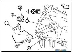
3. Remove the crankshaft position sensor cover (3), and then crankshaft position sensor (POS) (2).

(1) Oring

(4) Cylinder block

: Engine front

CAUTION:

  • Avoid impacts such as a dropping.
  • Do not disassemble.
  • Keep sensor away from metal particles.
  • Do not place the sensor in a location where it is exposed to magnetism.
  • Do not reuse Oring.
CYLINDER BLOCK

4. Remove oil pan (upper and lower).

5. Remove piston and connecting rod assembly:

  • Before removing piston and connecting rod assembly, check the connecting rod side clearance.

a. Position crankshaft pin corresponding to connecting rod to be removed onto the bottom dead center.

b. Remove connecting rod cap.

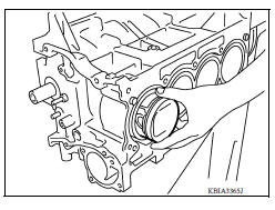
c. Using a hammer handle or similar tool, push piston and connecting rod assembly out through the cylinder head side.

CAUTION:

  • Be careful not to damage mating surface with connecting rod cap.
  • Be careful not to damage the cylinder wall or crankshaft pin.
CYLINDER BLOCK

6. Remove connecting rod bearings.

CAUTION:

Identify original positions for installation, and store the bearings without mixing them up.

7. Remove piston rings from piston.

  • Before removing piston rings, check the piston ring side clearance. Refer to EM103, "Inspection".
  • Use a suitable tool) (A) as shown.

CAUTION:

  • When removing piston rings, be careful not to damage the piston.
  • Be careful not to damage piston rings by expanding them excessively.
CYLINDER BLOCK

8. Remove piston from connecting rod.

  • Use a Tools (A, B, C) and a press to remove the piston pin.

Tool Number (A) : KV10109730

(B) : KV10110310

(C) : ST13030020

CAUTION:

  • Do not damage the piston and connecting rod.
  • Do not reuse piston and piston pin after removing piston pin from connecting rod.
  • The connecting rod is reusable.

NOTE:

The joint between the connecting rod and the piston pin is a press fit.

CYLINDER BLOCK

9. Remove the main bearing cap.

  • Measure crankshaft end play before loosening main bearing cap bolts.

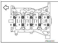
a. Loosen and remove bolts in several steps in reverse of the numerical order as shown.

: Engine front

NOTE:

When removing or installing signal plate, use socket (size T40).
CYLINDER BLOCK

b. Remove the main bearing cap from the cylinder block while tapping lightly with a plastic hammer.

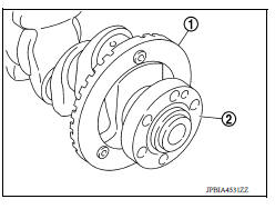
10. Remove crankshaft (2).

CAUTION:

  • Be careful not damage or deform signal plate (1) mounted on crankshaft.
  • When setting crankshaft on a flat floor surface, use a block of wood to avoid interference between signal plate and the floor surface.
  • Do not remove signal plate unless it is necessary to do so.

NOTE:

When removing or installing signal plate, use socket (size T40).
CYLINDER BLOCK

11. Pull rear oil seal out from rear end of crankshaft.

12. Remove main bearing (upper and lower) and thrust bearings from cylinder block and main bearing caps.

CAUTION:

Identify original installation positions, and store the bearings without mixing them up.

13. Remove oil jets.

CAUTION:

Insert the dowel pin of oil jet into the cylinder block dowel pin hole to loosen the bolt.

ASSEMBLY

CAUTION:

Do not reuse Orings.

1. Fully airblow engine coolant and engine oil passages in cylinder block, cylinder bore and crankcase to remove any foreign material.

WARNING:

Use goggles to protect your eyes.

2. Install oil jets.

3. Install main bearings and thrust bearings:

a. Remove dust, dirt, and engine oil on the bearing mating surfaces of cylinder block.

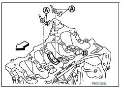
b. Install thrust bearings to the both sides of the No. 3 journal housing (B) on cylinder block.

: Engine front

  • Install thrust bearings with the oil groove (A) facing crankshaft arm (outside).
CYLINDER BLOCK

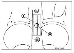
c. Install the main bearings paying attention to the direction.

  • Before installing main bearings, apply new engine oil to the bearing surface (inside). Do not apply engine oil to the back surface, but thoroughly clean it.
  • When installing, align main bearing to the center position of cylinder block and main bearing cap.
  • Ensure the oil holes on cylinder block and oil holes (A) on the main bearings (1) are aligned.

NOTE:

For assembly, the center position can be visually identified.

  • To install the main bearing, obtain a proper fit. Do not allow the main bearing to lie off the cylinder block chamfer.
  • To install the main bearing, obtain a proper fit. Do not allow the main bearing to lie off bearing cap chamfer.
CYLINDER BLOCK

4. Install signal plate to crankshaft if removed.

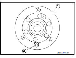
a. Set the signal plate (1) with the flange facing toward the counterweight side (engine front side) to the crankshaft rear surface.

(A) : Dowel pin hole

b. After positioning crankshaft and signal plate with positioning dowel pin, tighten bolt.

NOTE:

Dowel pin of crankshaft and signal plate is provided as a set for each.

c. Remove dowel pin.

CAUTION:

Be sure to remove dowel pin.
CYLINDER BLOCK

5. Install crankshaft to cylinder block.

  • While turning crankshaft by hand, check that it turns smoothly.

CAUTION:

Do not install rear oil seal at this time.

6. Install main bearing caps

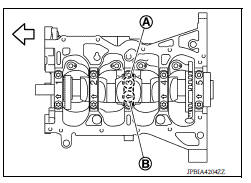
  • Install the main bearing cap while referring to the front mark (B) and the journal number stamp (A).

: Engine front

NOTE:

Main bearing cap cannot be replaced as a single part, because it is machined together with cylinder block.
CYLINDER BLOCK

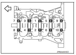
7. Tighten main bearing cap bolts in numerical order as shown with the following steps:

: Engine front

a. Apply new engine oil to threads and seat surfaces of the bolts.

b. Tighten main bearing cap bolts in numerical order.

Main bearing cap bolts : 32.4 N*m (3.3 kgm, 24 ftlb)
CYLINDER BLOCK

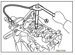
c. Turn main bearing cap bolts 60 degrees clockwise (angle tightening) in numerical order as shown.

CAUTION:

Check and confirm the tightening angle by using the Tool (A) or protractor. Avoid judgment by visual inspection without the Tool.

Tool number : KV10112100 (BT8653A)
CYLINDER BLOCK
  • After installing the main bearing cap bolts, check that crankshaft can be rotated smoothly by hand.
  • Check crankshaft end play.

8. Install piston to connecting rod with the following procedure:

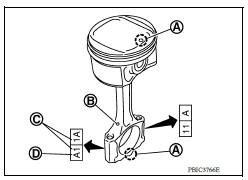
a. Set so that the front mark (A) on the piston head and the cylinder number (C) are in the position as shown.

(B) : Oil hole

(D) : Connecting rod big end grade

NOTE:

The symbols without notes are for manufacturing.

CYLINDER BLOCK

b. Pressfit the piston pin using the Tools (A, B, C, D, E).

Tool number (A) : KV10109730

(B) : KV10110310

(C) : ST13030020

(D) : KV10114120

(E) : ST13030030

(F) : Detail

CAUTION:

Pressfit the piston so as not to damage it.

NOTE:

The joint between the connecting rod and the piston pin is a press fit.

CYLINDER BLOCK
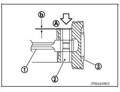
  • Pressfit the piston pin (2) from piston surface (A) to the depth of 2.35 mm (0.092 in) (b).

(1) : Connecting rod

: Pressfit direction

  • After finishing work, check that the piston (3) moves freely.
CYLINDER BLOCK

9. Using suitable tool (A), install piston rings.

CAUTION:

  • Be careful not to damage piston.
  • Be careful not to damage piston rings by expanding them excessively.
CYLINDER BLOCK
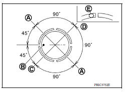
  • Position each ring with the gap as shown referring to the piston front mark (B).

(A) : Oil ring upper or lower rail gap (either of them)

(C) : Second ring and oil ring spacer gap

(D) : Top ring gap

  • Install second ring with the stamped mark (E) facing upward.
CYLINDER BLOCK

Stamped mark:

Top ring : 1R

Second ring : 2R

10. Install connecting rod bearings to connecting rod and connecting rod cap.

  • When installing connecting rod bearings, apply new engine oil to the bearing surface (inside). Do not apply engine oil to the back surface, but thoroughly clean it.
  • Install the bearing in the center position.

NOTE:

There is no stopper tab.

  • Check that the oil holes on connecting rod and connecting rod bearing are aligned.
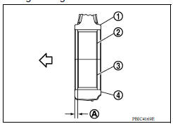
  • Install the connecting rod in the dimension (A) as shown.

(1) : Connecting rod

(2) : Connecting rod bearing (upper)

(3) : Connecting rod bearing (lower)

(4) : Connecting rod cap

(A) : 1.7 2.1 mm (0.067 0.083 in)

: Engine front

NOTE:

Install the connecting rod bearing in the center position with the dimension as shown. For service operation, the center position can be checked visually.
CYLINDER BLOCK

11. Install piston and connecting rod assembly to crankshaft.

  • Position crankshaft pin corresponding to connecting rod to be installed onto the bottom dead center.
  • Apply new engine oil sufficiently to the cylinder bore, piston and crankshaft pin.
  • Match the cylinder position with the cylinder number on connecting rod to install.
  • Using Tool (A) or suitable tool, install piston with the front mark on the piston head facing the front of the engine.

CAUTION:

  • Be careful not to damage mating surface with connecting rod cap.
  • Be careful not to damage the cylinder wall or crankshaft pin.

Tool number : EM03470000

CYLINDER BLOCK

12. Install connecting rod cap.

  • Match the stamped cylinder number marks (C) on connecting rod with those on connecting rod cap to install.

(A) : Front mark

(B) : Oil hole

(D) : Connecting rod big end grade
CYLINDER BLOCK

13. Inspect outer diameter of connecting rod bolts.

14. Tighten connecting rod bolt:

a. Apply new engine oil to the threads and seats of connecting rod bolts.

b. Tighten connecting rod bolts in several steps.

Connecting rod bolts : 27.4 N*m (2.8 kgm, 20 ftlb)

c. Completely loosen connecting rod bolts.

Connecting rod bolts : 0 N*m (0 kgm, 0 ftlb)

d. Tighten connecting rod bolts in several steps.

Connecting rod bolts : 19.6 N*m (2.0 kgm, 14 ftlb)

e. Then turn all connecting rod bolts 60 degrees clockwise (angle tightening).

CAUTION:

Check and confirm the tightening angle by using the Tool (A) or protractor. Avoid judgement by visual inspection without the Tool.

Tool number : KV10112100 (BT8653A)

CYLINDER BLOCK
  • After tightening connecting rod bolt, check that crankshaft rotates smoothly.
  • Check the connecting rod side clearance.

15. Install oil pan (upper).

NOTE:

Install the rear oil seal after installing the oil pan (upper).

16. Install rear oil seal.

17. Install flywheel (M/T models) or drive plate (A/T and CVT models).

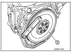
M/T models

  • Secure crankshaft with a stopper plate (A) and tighten bolts crosswise over several times.

(1) :Flywheel

Tool number : KV11105210 (J44716)
CYLINDER BLOCK

A/T and CVT models

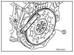
  • Secure crankshaft with a stopper plate (A) and tighten bolts crosswise over several times

(1) :Drive plate

Tool number : KV11105210 (J44716)
CYLINDER BLOCK

CAUTION:

Be careful not to damage or scratch and contact surface for clutch disc of flywheel.

18. Install knock sensor (1).

: Engine front

  • Install connectors so that they are positioned toward the rear of the engine.

CAUTION:

  • Do not tighten bolt while holding the connector.
  • If any impact by dropping is applied to knock sensor, replace it with a new one.

NOTE:

  • Check that there is no foreign material on the cylinder block mating surface and the back surface of knock sensor.
  • Check that knock sensor does not interfere with other parts.
CYLINDER BLOCK

19. Install crankshaft position sensor (POS) (2) using a new Oring (1) and then install the crankshaft position sensor cover (3) on the cylinder block (4).

  • Tighten bolts with sensor inserted completely.

: Engine front

CYLINDER BLOCK

CAUTION:

  • Avoid impacts such as a dropping.
  • Do not disassemble.
  • Keep sensor away from metal particles.
  • Do not place the sensor in a location where it is exposed to magnetism.
  • Do not reuse Oring.

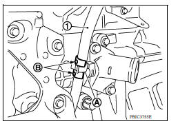
20. For the oil level gauge guide (1), secure in position (B) shown to the water inlet clip (A) after inserting to the cylinder block side.
CYLINDER BLOCK

21. Assembly of the remaining components is in the reverse order of disassembly.

Inspection

CRANKSHAFT END PLAY

  • Measure the clearance between thrust bearings and crankshaft arm when crankshaft is moved fully forward or backward with a suitable tool (A).
  • If the measured value exceeds the limit, replace thrust bearings, and measure again. If it still exceeds the limit, replace crankshaft also.
CRANKSHAFT END PLAY

CONNECTING ROD SIDE CLEARANCE

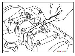
  • Measure the side clearance between connecting rod and crankshaft arm with a suitable tool (A).
  • If the measured value exceeds the limit, replace connecting rod, and measure again. If it still exceeds the limit, replace crankshaft also.
CONNECTING ROD SIDE CLEARANCE

PISTON TO PISTON PIN OIL CLEARANCE

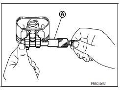
Piston Pin Hole Diameter Measure the inner diameter of piston pin hole with an suitable tool (A).
PISTON TO PISTON PIN OIL CLEARANCE

Piston Pin Outer Diameter Measure the outer diameter of piston pin with a suitable tool (A).

PISTON TO PISTON PIN OIL CLEARANCE

Piston to Piston Pin Oil Clearance (Piston to piston pin oil clearance) = (Piston pin hole diameter) - (Piston pin outer diameter)

  • If oil clearance is out of the standard, replace piston and piston pin assembly.
  • When replacing piston and piston pin assembly.

NOTE:

  • Piston is available together with piston pin as assembly.
  • Piston pin (piston pin hole) grade is provided only for the parts installed at the factory. For service parts, no grades can be selected. Only grade "0" is available.

PISTON RING SIDE CLEARANCE

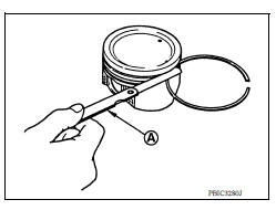
  • Measure the side clearance of piston ring and piston ring groove with a suitable tool (A).
  • If the measured value exceeds the limit, replace piston ring, and measure again. If it still exceeds the limit, replace piston also.
PISTON RING SIDE CLEARANCE

PISTON RING END GAP

  • Check that cylinder bore inner diameter is within specification. Refer to "PISTON TO CYLINDER BORE CLEARANCE".
  • Lubricate piston (1) and piston ring (2) with new engine oil and then insert (A) piston ring until middle of cylinder (B) with piston, and measure piston ring end gap with a feeler gauge (C).
  • If the measured value exceeds the limit, replace piston ring, and measure again. If it still exceeds the limit, replace cylinder block.
PISTON RING END GAP

CONNECTING ROD BEND AND TORSION

  • Check with a connecting rod aligner.

(A) : Bend

(B) : Torsion

(C) : Feeler gauge

  • If it exceeds the limit, replace connecting rod assembly.
CONNECTING ROD BEND AND TORSION

CONNECTING ROD BIG END DIAMETER

  • Install connecting rod cap (1) without connecting rod bearing installed, and tightening connecting rod cap bolts to the specified torque.

(2) : Connecting rod

(A) : Example

(B) : Measuring direction of inner diameter

  • Measure the inner diameter (B) of connecting rod big end with a suitable tool.
  • If out of the standard, replace connecting rod assembly.
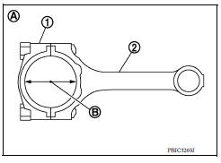
CONNECTING ROD BIG END DIAMETER

CONNECTING ROD BUSHING OIL CLEARANCE

Connecting Rod Bushing Inner Diameter Measure the inner diameter of connecting rod bushing with a suitable tool (A).
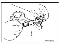
CONNECTING ROD BUSHING OIL CLEARANCE

Piston Pin Outer Diameter Measure the outer diameter of piston pin with a micrometer (A).

CONNECTING ROD BUSHING OIL CLEARANCE

Connecting Rod Bushing Oil Clearance (Connecting rod bushing oil clearance) = (Connecting rod bushing inner diameter) - (Piston pin outer diameter)

  • If the measured value is out of the standard range, replace connecting rod assembly and/or piston and piston pin assembly.
  • If replacing piston and piston pin assembly.
  • If replacing connecting rod assembly.

CYLINDER BLOCK TOP SURFACE DISTORTION

  • Using a scraper, remove gasket on the cylinder block surface, and also remove engine oil, scale, carbon, or other contamination.

CAUTION:

Be careful not to allow gasket particles to enter engine oil or engine coolant passages.

  • Measure the distortion on the cylinder block upper face at different points in six directions with a suitable tool (A) and (B).
  • If it exceeds the limit, replace cylinder block.
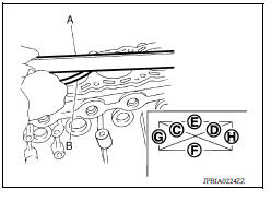
CYLINDER BLOCK TOP SURFACE DISTORTION

MAIN BEARING HOUSING INNER DIAMETER

  • Install main bearing cap without main bearings installed, and tighten main bearing cap bolts to the specified torque.
  • Measure the inner diameter of main bearing housing with a suitable tool.
  • Measure the position shown [5 mm (0.20 in)] backward from main bearing housing front side in the 2 directions as shown. The smaller one is the measured value.

(1) : Cylinder block

(2) : Main bearing cap

: Engine front

  • If out of the standard, replace cylinder block and main bearing caps assembly.

NOTE:

Main bearing caps cannot be replaced individually, because they are machined together with cylinder block.
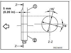
MAIN BEARING HOUSING INNER DIAMETER

PISTON TO CYLINDER BORE CLEARANCE

Cylinder Bore Inner Diameter

  • Using a suitable tool, measure the cylinder bore for wear, outofround and taper at six different points on each cylinder. [(A) and (B) directions at (C), (D), and (E)] [(A) is in longitudinal direction of engine]

(f) : 10 mm (0.39 in)

(g) : 60 mm (2.36 in)

(h) : 124 mm (4.88 in)

NOTE:

When determining cylinder bore grade, measure the cylinder bore (B) direction at (D) position.
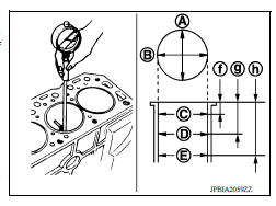
PISTON TO CYLINDER BORE CLEARANCE
  • If the measured value exceeds the limit, or if there are scratches and/or seizure on the cylinder inner wall, replace cylinder block.

NOTE:

Oversize piston is not available.

Piston Skirt Diameter Measure the outer diameter of piston skirt with a suitable tool (A).
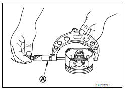
PISTON TO CYLINDER BORE CLEARANCE

Piston to Cylinder Bore Clearance Calculate by piston skirt diameter and cylinder bore inner diameter [direction (B), position (D)].

(A) : Direction A

(C) : Position C

(E) : Position E

(f) : 10 mm (0.39 in)

(g) : 60 mm (2.36 in)

(h) : 124 mm (4.88 in)

(Clearance) = (Cylinder bore inner diameter) - (Piston skirt diameter)

PISTON TO CYLINDER BORE CLEARANCE
  • If it exceeds the limit, replace piston and piston pin assembly and/or cylinder block.

CRANKSHAFT MAIN JOURNAL DIAMETER

  • Measure the outer diameter of crankshaft main journals with a suitable tool (A).
  • If out of the standard, measure the main bearing oil clearance.

    Then use undersize bearing.
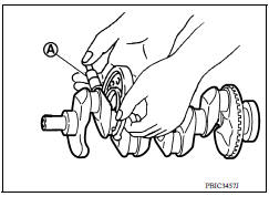
CRANKSHAFT MAIN JOURNAL DIAMETER

CRANKSHAFT PIN JOURNAL DIAMETER

  • Measure the outer diameter of crankshaft pin journal with a suitable tool.
  • If out of the standard, measure the connecting rod bearing oil clearance.

OUTOFROUND AND TAPER OF CRANKSHAFT

  • Measure the dimensions at four different points as shown on each main journal and pin journal with a suitable tool.

  • Outofround is indicated by the difference in dimensions between (a) and (b) at (c) and (d).

  • Taper is indicated by the difference in dimension between (c) and (d) at (a) and (b).

  • If the measured value exceeds the limit, correct or replace crankshaft.

  • If corrected, measure the bearing oil clearance of the corrected main journal and/or pin journal. Then select main bearing and/or connecting rod bearing.
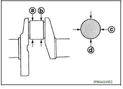
OUTOFROUND AND TAPER OF CRANKSHAFT

CRANKSHAFT RUNOUT

  • Place a Vblock on a precise flat table to support the journals on both ends of the crankshaft.
  • Place a suitable tool (A) straight up on the No. 3 journal.
  • While rotating crankshaft, read the movement of the pointer on the suitable tool. (Total indicator reading)
  • If it exceeds the limit, replace crankshaft.
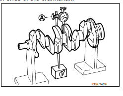
CRANKSHAFT RUNOUT

CONNECTING ROD BEARING OIL CLEARANCE

Method by Calculation

  • Install connecting rod bearings (2) to connecting rod (3) and connecting rod cap (1), and tighten connecting rod cap bolts to the specified torque.

(A) : Example

(B) : Inner diameter measuring direction

  • Measure the inner diameter of connecting rod bearing with a suitable tool.

    (Bearing oil clearance) = (Connecting rod bearing inner diameter) - (Crankshaft pin journal diameter)
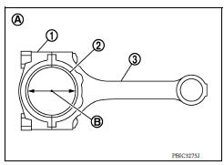
CONNECTING ROD BEARING OIL CLEARANCE
  • If clearance exceeds the limit, select proper connecting rod bearing according to connecting rod big end diameter and crankshaft pin journal diameter to obtain specified bearing oil clearance.

Method of Using Plastigage

  • Remove engine oil and dust on crankshaft pin and the surfaces of each bearing completely.
  • Cut a plastigage slightly shorter than the bearing width, and place it in crankshaft axial direction, avoiding oil holes.
  • Install connecting rod bearings to connecting rod and cap, and tighten connecting rod cap bolts to the specified torque.

CAUTION:

Do not rotate crankshaft.

  • Remove connecting rod cap and bearing, and using the scale (A) on the plastigage bag, measure the plastigage width.

NOTE:

The procedure when the measured value exceeds the limit is same as that described in the "Method by Calculation".

CONNECTING ROD BEARING OIL CLEARANCE

MAIN BEARING OIL CLEARANCE

Method by Calculation

  • Install main bearings (3) to cylinder block (1) and main bearing cap (2), and tighten main bearing cap bolts to the specified torque.

(A) : Example

(B) : Inner diameter measuring direction

  • Measure the inner diameter (B) of main bearing (3) with a suitable tool.

    (Bearing oil clearance) = (Main bearing inner diameter) - (Crankshaft main journal diameter)

  • If clearance exceeds the limit, select proper main bearing according to main bearing inner diameter and crankshaft main journal diameter to obtain specified bearing oil clearance.
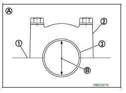
MAIN BEARING OIL CLEARANCE

Method of Using Plastigage

  • Remove engine oil and dust on crankshaft main journal and the surfaces of each bearing completely.
  • Cut a plastigage slightly shorter than the bearing width, and place it in crankshaft axial direction, avoiding oil holes.
  • Install main bearings to cylinder block and main bearing cap, and tighten main bearing cap bolts to the specified torque.

CAUTION:

Do not rotate crankshaft.

  • Remove main bearing cap and bearings, and using the scale (A) on the plastigage bag, measure the plastigage width.

NOTE:

The procedure when the measured value exceeds the limit is same as that described in the "Method by Calculation".
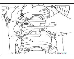
MAIN BEARING OIL CLEARANCE

MAIN BEARING CRUSH HEIGHT

  • When main bearing cap is removed after being tightened to the specified torque with main bearings (1) installed, the tip end of bearing must protrude (B).

(A) : Example

Standard : There must be crush height.

  • If the standard is not met, replace main bearings.
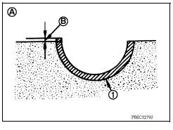
MAIN BEARING CRUSH HEIGHT

CONNECTING ROD BEARING CRUSH HEIGHT

  • When connecting rod cap is removed after being tightened to the specified torque with connecting rod bearings (1) installed, the tip end of bearing must protrude (B).

(A) : Example

Standard : There must be crush height.

  • If the standard is not met, replace connecting rod bearings.
CONNECTING ROD BEARING CRUSH HEIGHT

MAIN BEARING CAP BOLT OUTER DIAMETER

  • Measure the outer diameters (d1) and (d2) at two positions as shown.

(A) : (d1) measuring position

(B) : (d2) measuring position

  • If reduction appears in places other than (B) range, regard it as (d2).

Limit [(d1) - (d2)]: 0.2 mm (0.0078 in)

  • If it exceeds the limit (a large difference in dimensions), replace main bearing cap bolt with a new one.
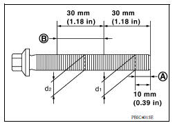
MAIN BEARING CAP BOLT OUTER DIAMETER

CONNECTING ROD CAP BOLT OUTER DIAMETER

  • Measure the outer diameter (d) at position as shown.
  • If reduction appears in a position other than (d), regard it

Limit: 7.75 mm (0.3051 in)

  • When (d) is less than the limit (when it becomes thinner), replace connecting rod cap bolt with a new one.
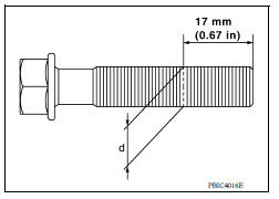
CONNECTING ROD CAP BOLT OUTER DIAMETER

FLYWHEEL DEFLECTION (M/T models)

  • Measure the deflection of flywheel contact surface to torque with a suitable tool (A).
  • Measure the deflection at 210 mm (8.27 in) diameter.

Limit : 0.45 mm (0.0177 in) or less.

  • If measured value is out of the standard, replace flywheel.
  • If a trace of burn or discoloration is found on the surface, clean it with sandpaper.

CAUTION:

When measuring, keep magnetic fields (such as dial indicator stand) away from signal plate of the rear end of crankshaft.
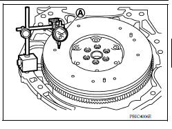
FLYWHEEL DEFLECTION (M/T models)