Audio Remote Switch Test
In this manual: Audio Remote Switch Test
24steps
~144min
4/5difficulty
Done 0 of 24
Test
SRS components are located in this area. Review the SRS component locations and the precautions and procedures before doing repairs or service.
1. Steering Wheel Trim - Remove
2. Audio Remote Switch - Test

- Measure the resistance between terminals No. 2 and No. 5 in each switch position according to the table.
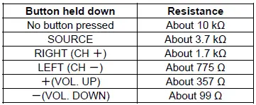
- Display audio type (8-inch screen): Measure the resistance between terminals No. 3 and No. 5 in each switch position according to the table.
Display Audio Type (8-inch Screen)

- If the resistance is not as specified, replace the audio remote switch.
3. All Removed Parts - Install
- Install the parts in the reverse order of removal.
Auto High-Beam (High-Beam Support System) C-MOS Camera Light Source Test
Cautions for the test environment
- The C-MOS camera must be fixed.
- There should be no bright objects behind or to the sides of the target vehicle (sunlight, windows, illumination, or reflectors).
- The test should be done a dark in area (15 lux or less).
- The target vehicle should only have OEM headlight and taillight bulbs installed.
Set up the vehicle
- All wheels of the vehicle should touch the ground.
- Make sure the steering wheel is straight ahead, and do not turn it after setting up the vehicle.
- Make sure that all doors are closed.
- Do not put any objects on the instrument panel.
- Before testing, clean the lens of the C-MOS camera with dry cloth, and the interior and exterior surface of the windshield of the lens parts.
- Shift to the neutral position, and apply the parking brake.
- Make sure that the headlights or taillights of the target vehicle should face the C-MOS camera.
Confirm C-MOS camera
- Setting the distance between the target vehicle (A) and customer's vehicle (B).
Headlight (White light source)
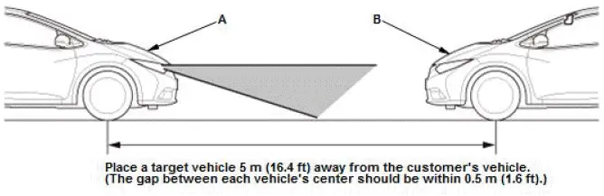
Taillight (Red light source)

- Connect the HDS to the data link connector (DLC).
- Turn the vehicle to the ON mode.
- From the BODY ELECTRICAL SYSTEM SELECT menu, select AUTO HIGH-BEAM, then FUNCTION TEST.
- Do the test in this order:
- ONCOMING VEHICLE DETECTION
- PRECEDING VEHICLE DETECTION
- The C-MOS camera does not detect the light source and is faulty; Substitute or replace a known-good C-MOS camera or replace the rearview mirror.
Auto High-Beam (High-Beam Support System) Control Unit Input Test
NOTE:
- Before testing, check for DTCs. If any DTCs are indicated, troubleshoot the indicated DTCs first.
- If you are troubleshooting multiple DTCs, be sure to follow the instructions in B-CAN System Diagnosis Test Mode A.
- Before testing, make sure the No. C23 (7.5 A) fuse in the under-dash fuse/relay box is OK.
- Disconnect the auto high-beam control unit 6P connector.

- Inspect the connector and socket terminals to be sure they are all making good contact:
- If the terminals are bent, loose, or corroded, repair them as necessary, and recheck the system.
- If the terminals look OK, go to step 3.
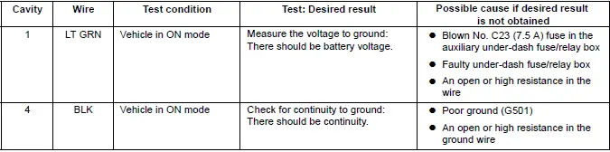
- With the connector still disconnected, do the following input tests:
- If any test indicates a problem, find and correct the cause, then recheck the system.
- If all the input tests prove OK, replace the auto high-beam control unit.
Automatic Dimming Mirrors Test
NOTE: Before testing, check for B-CAN DTCs. If any B-CAN DTCs are indicated, troubleshoot the indicated B-CAN DTCs first.
- Turn the vehicle to the ON mode.
- Measure the voltage between terminal No. 1 and body ground.
- If there is battery voltage, go to step 3.
- If there is no voltage, check for:
- Blown No. C23 (7.5 A) fuse in the under-dash fuse/relay box.
- An open or high resistance in the wire.

- Measure the voltage between terminal No. 4 and body ground.
- If there is less than 0.2 V, replace the rearview mirror.
- If there is voltage more than 0.2 V, check for:
- An open or high resistance in the ground wire.
- Poor ground (G501).
Automatic Dimming Mirrors Test
- Turn the vehicle to ON mode.
- Measure the voltage between terminal No. 7 and body ground.
- If there is battery voltage, go to step 3.
- If there is no voltage, check for:
- Blown No. C23 (7.5 A) fuse in the under-dash fuse/relay box.
- An open or high resistance in the wire.
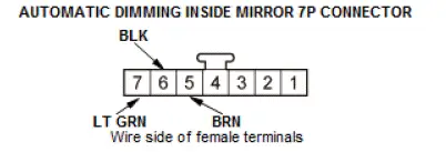
- Measure the voltage between terminal No. 6 and body ground.
- If there is continuity, go to step 4.
- If there is no continuity, check for:
- An open or high resistance in the ground wire.
- Poor ground (G501).
- Measure the voltage between terminal No. 5 and body ground with the transmission range switch in R position.
- If there is battery voltage, replace the rearview mirror.
- If there is no voltage, check for:
- Blown No. C29 (7.5 A) fuse in the under-dash fuse/relay box.
- An open or high resistance in the wire.
- Faulty under-dash fuse/relay box
- Faulty TCM (9-speed A/T)
- Faulty transmission range switch (6-speed A/T)
Automatic Lighting Control Unit-Sensor Input Test
NOTE:
- Before testing, check for DTCs. If any DTCs are indicated, troubleshoot those DTCs first.
- If you are troubleshooting multiple DTCs, be sure to follow the instructions in B-CAN System Diagnosis Test Mode A.
- Before testing, make sure the No. A26 (10 A) fuse in the under-hood fuse/relay box is OK.
- Turn the vehicle to the OFF (LOCK) mode.
- Disconnect the automatic control unit 5P connector.

- Inspect the connector and socket terminals to be sure they are all making good contact:
- If the terminals are bent, loose, or corroded, repair them as necessary, and recheck the system.
- If the terminals are OK, go to step 4.
- Reconnect the connector, and do the following input tests:
- If any test indicates a problem, find and correct the cause, then recheck the system.
- If all the input tests prove OK, replace the automatic lighting control unit-sensor.
| Cavity | Wire | Test condition | Test: Desired result | Possible cause if desired result is not obtained |
| 4 | WHT | Under all conditions | Measure the voltage to ground: There should be battery voltage. |
|
| 3 | BLK | In all power modes | Measure the voltage to ground: There should be less than 0.2 V. |
|
| 5 | BRN | Combination light switch in any position, other than headlight ON. | Measure the voltage to ground: There should be about 5 V. | An open or high resistance in the wire |
Automatic Lighting/Rain Sensor Input Test
NOTE:
- Before testing, check for DTCs. If any DTCs are indicated, troubleshoot those DTCs first.
- If you are troubleshooting multiple DTCs, be sure to follow the instructions in B-CAN System Diagnosis Test Mode A.
- Before testing, make sure the No. D6 (10 A) fuse in the auxiliary under-dash fuse/relay box is OK.
- Turn the vehicle to the OFF (LOCK) mode.
- Disconnect the automatic lighting/rain sensor 5P connector.
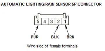
- Inspect the connector and socket terminals to be sure they are all making good contact:
- If the terminals are bent, loose, or corroded, repair them as necessary, and recheck the system.
- If the terminals are OK, go to step 4.
- Reconnect the connector, and do the following input tests:
- If any test indicates a problem, find and correct the cause, then recheck the system.
- If all the input tests prove OK, replace the automatic lighting/rain sensor.
| Cavity | Wire | Test condition | Test: Desired result | Possible cause if desired result is not obtained |
| 5 | PUR | Under all conditions | Measure the voltage to ground: There should be battery voltage. |
|
| 2 | BLK | In all power modes | Measure the voltage to ground: There should be less than 0.2 V. |
|
| 1 | BRN | Combination light switch in any position, other than headlight ON. | Measure the voltage to ground: There should be about 5 V. | An open or high resistance in the wire |
Was this page helpful?