Steering Gearbox Removal and Installation
Removal
NOTE:
- Using clean solvent and a brush, wash any oil and dirt off the end of the steering gearbox. Blow dry with compressed air.
- Lower the front subframe from the body, and remove the steering gearbox through the gap produced by lowering the front subframe.
1. Steering Column Tilt and Telescopic Position - Set
- Set the steering column to the center tilt position, and to the center telescopic position.
2. Vehicle - Lift
3. Front Wheel - Remove
4. Front Door Sill Trim - Remove
5. Kick Panel - Remove
6. Center Console Side Cover - Remove (Driver's Side)
7. Steering Wheel - Hold
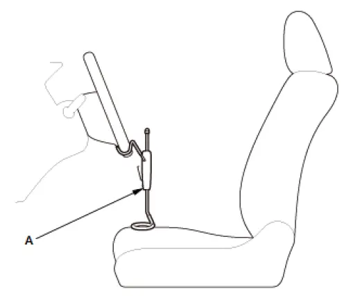
- Center the steering wheel spoke angle.
- Install a commercially available steering wheel holder tool (A).
8. Steering Joint - Disconnect
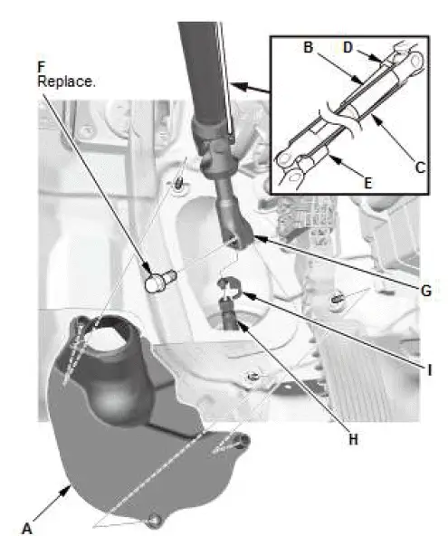
- Remove the steering joint cover (A).
- Hold the spline shaft (B) on the column with a piece of wire (C) between the joint yoke (D) of the spline shaft and the joint yoke (E) of the spline tube to prevent the lower spline shaft from pulling out.
- Remove the steering joint bolt (F).
- Disconnect the steering joint (G) from the pinion shaft (H).
- Remove the center guide (I) (if equipped), and discard it.
- Wrap vinyl tape to the splines on the pinion shaft.
9. Engine Cover - Remove
10.Front Bulkhead Cover - Remove
11.Air Intake Tube - Remove
12.Engine Support Hanger - Install
- Support the engine with the engine hanger adapter set, the engine hanger balance bar, attachment arm, and the engine support hanger.
13.Tie-Rod End Ball Joint - Disconnect
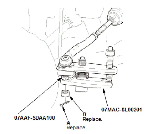
- Remove the cotter pin (A).
- Remove the nut (B).
- Disconnect the tie-rod end ball joint from the knuckle using the ball joint thread protector and the ball joint remover.
NOTE: Be careful not to damage the ball joint boot when installing the ball joint remover.
14.Power Steering Heat Shield - Remove
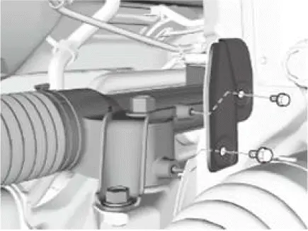
15.Steering Gearbox Stiffener - Remove
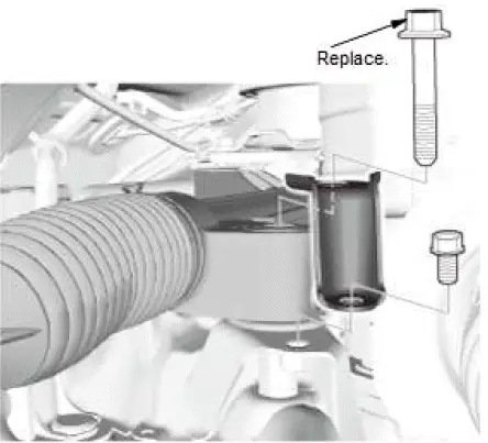
16.No. 6 Cylinder Ignition Coil - Remove
- Remove the No.6 cylinder ignition coil.
NOTE: No.6 cylinder arrangement.
17.Front Engine Mount Stop and Front Engine Mount Mounting Bolt - Remove
18.Splash Shield - Remove
19.Engine Undercover - Remove
20.Connector (Front Suspension Stroke Sensor) - Disconnect (With Auto Leveling System)
21.Front subframe stiffener plate - Remove
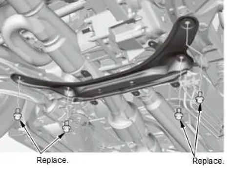
22.Under-Floor TWC - Remove
23.Rear Engine Mount - Remove
24.Rear Engine Mount Base Bracket - Remove
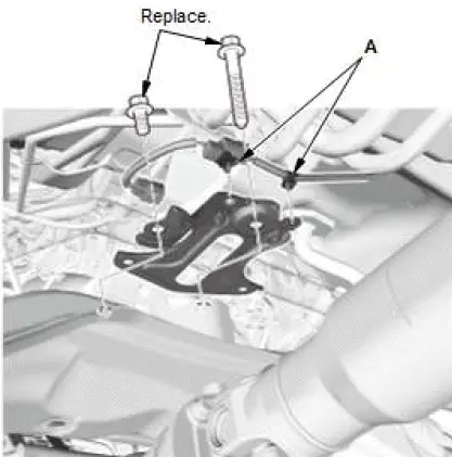
- Remove the harness clips (A).
25.Connector (Front Engine Mount Actuator) - Disconnect
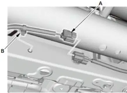
- Disconnect the connector (A).
- Remove the harness clip (B).
26.Front Subframe - Support

- Attach the subframe adapter (VSB02C000016) to the front subframe by looping the belt (A) over the front of the front subframe (B), then secure the belt with its stop (C).
- Raise the transmission jack and line up the slots in the subframe adapter arms with the bolt holes on the jack base, then securely attach them with four bolts.
27.Transmission Mount Mounting Bolts (Transmission Side) - Remove
28.Front Subframe - Lift Down
- Remove the front stiffener mounting bolts (A).
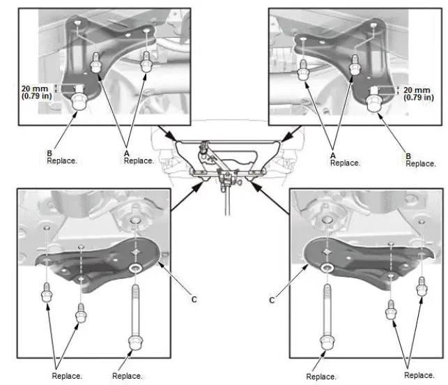
- Loosen the front subframe mounting bolts (B) so they are about 20 mm (0.79 in) from the mounting surface.
NOTE: Do not loosen the front subframe mounting bolts more than necessary.
- Remove the rear stiffeners (C).
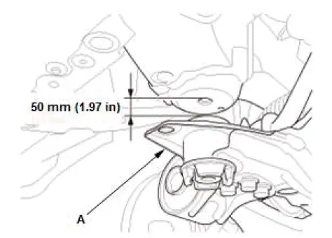
- Lower the jack slowly until the front subframe (A) has dropped.
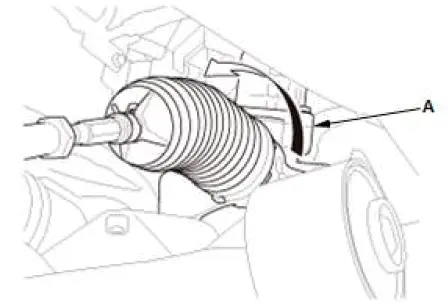
- Carefully move the steering gearbox (A) toward the front side until the pinion shaft is horizontal.
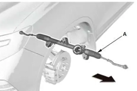
- Remove the steering gearbox (A) through the wheel well opening on the driver's side.
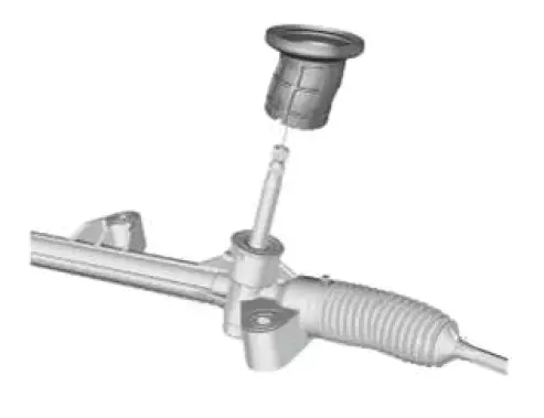
30.Pinion Shaft Grommet - Remove
Installation
NOTE:
- Using clean solvent and a brush, wash any oil and dirt off the end of the steering gearbox. Avoid any electrical parts. Blow dry with compressed air.
- Lower the front subframe from the body, and install the steering gearbox through the gap produced by lowering the front subframe.
1. Pinion Shaft Grommet - Install
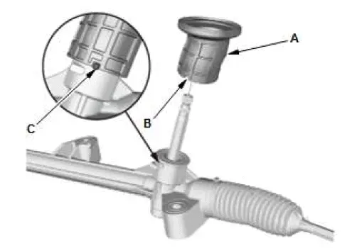
- Install the pinion shaft grommet (A).
- Align the cutout portion (B) with the tab portion (C).
- The grommet must not have a gap at the mating surface of the grommet and steering gearbox.
2. Steering Gearbox - Install
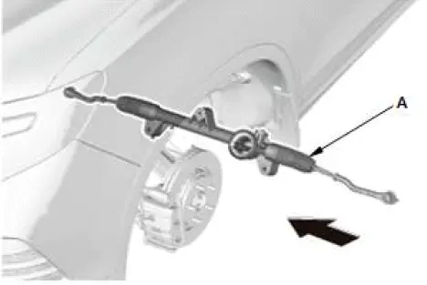
- Slide the steering gearbox (A) between the front subframe and the body from the driver's side.
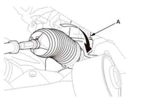
- Move the steering gearbox (A) until the steering gearbox is in position.
3. Front Subframe - Lift Up
- Raise the front subframe up to the body.
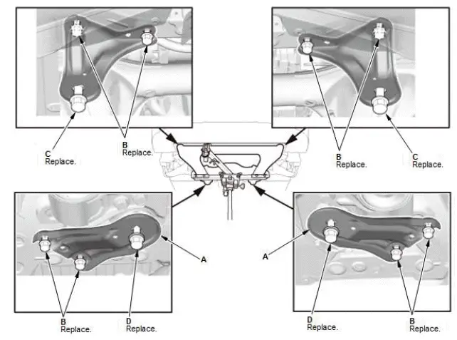
- Install the rear stiffeners (A).
- Loosely install the new front and rear stiffener mounting bolts (B)
- Replace the front subframe mounting bolts (C) with a new one, then loosely install them.
- Loosely install the new rear subframe mounting bolts (D).
4. Front Subframe - Tighten
- Align the front subframe with the subframe alignment pin, then tighten the mounting bolts to the specified torque.
5. Transmission Mount Mounting Bolts (Transmission Side) - Loosely Install
6. Subframe Jack - Release
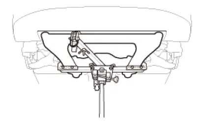
7. Connector (Front Engine Mount Actuator) - Connect
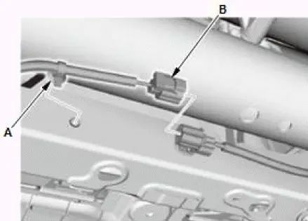
- Install the harness clip (A).
- Connect the connector (B).
8. Engine - Support
- Lift and support the engine with a jack and a wood block under the oil pan.
9. Rear Engine Mount Base Bracket - Loosely Install
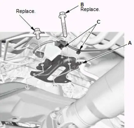
- Install the rear engine mount base bracket (A) with the new mounting bolt.
- Loosely install the new steering gearbox mounting bolt (B).
- Install the harness clips (C).
10.Rear Engine Mount - Loosely Install
11.Front Engine Mount Stop and Front Engine Mount Mounting Bolt - Loosely Install
12.Engine Support Hanger - Remove
- Remove the engine with the engine hanger adapter set, the engine hanger balance bar, attachment arm, and the engine support hanger.
13.Engine Mount - Tighten
14.No. 6 Cylinder Ignition Coil - Install
15.Steering Gearbox Stiffener - Loosely Install
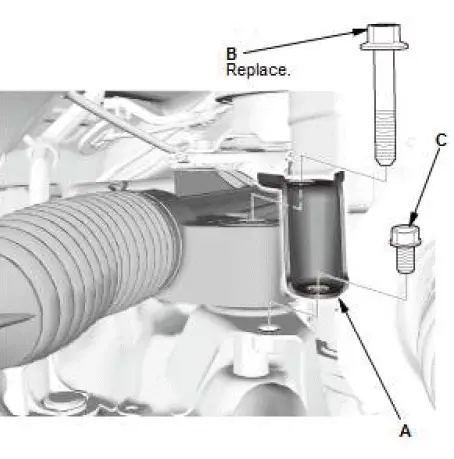
- Install the steering gearbox stiffener (A) on both sides.
- Loosely install the new steering gearbox mounting bolt (B) on both sides.
- Loosely install the stiffener mounting bolt (C) on both sides.
16.Power Steering Heat Shield - Install
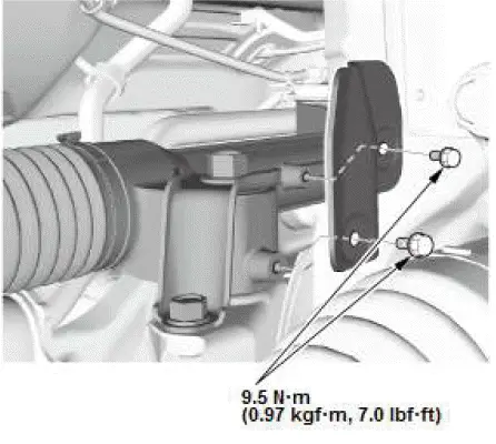
17.Steering Gearbox Mounting Bolt - Tighten
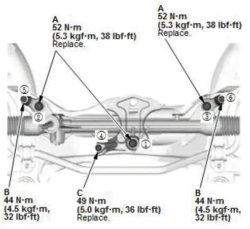
- Tighten the steering gearbox mounting bolts (A), the stiffener mounting bolts (B) and the rear engine mount base bracket mounting bolt (C) to the specified torque in the numbered sequence shown.
18.Under-Floor TWC - Install
19.Front subframe stiffener plate - Install
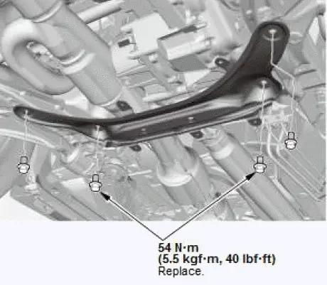
20.Connector (Front Suspension Stroke Sensor) - Connect (With Auto Leveling System)
21.Engine Undercover - Install
22.Splash Shield - Install
23.Tie-Rod End Ball Joint - Connect
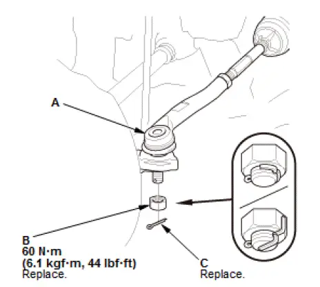
- Wipe off any grease contamination from the ball joint tapered section and threads.
- Connect the tie-rod ball joint (A) to the knuckle.
- Install a new nut (B) and tighten to the specified torque.
- Install a new cotter pin (C).
NOTE: Bend the cotter pin as shown.
24.Air Intake Tube - Install
25.Front Bulkhead Cover - Install
26.Engine Cover - Install
27.Steering Wheel - Release
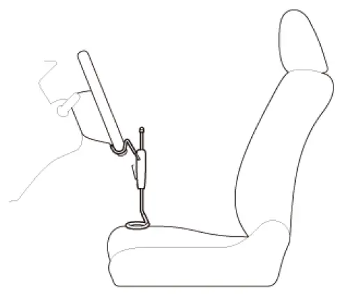
28.Steering Joint - Connect
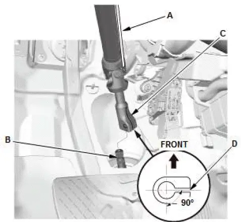
- Cut the wire (A).
- Set the rack in the straight ahead driving position.
- Remove the vinyl tape from the pinion shaft (B).
- Slip the lower end of the steering joint (C) onto the pinion shaft.
NOTE: Position the steering column by aligning the gap (D) within the angle.
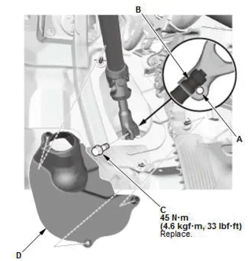
- Align the bolt hole (A) on the steering joint with the groove (B) around the pinion shaft.
- Loosely install the steering joint bolt (C).
- Be sure that the joint bolt is securely in the groove in the pinion shaft.
- Pull on the steering joint to make sure that the steering joint is fully seated.
- Tighten the steering joint bolt to the specified torque.
NOTE: Install the steering joint bolt and tighten it within 5 minutes using the specified tightening torque.
- Install the steering joint cover (D).
NOTE: Check the steering joint cover for damage and cracks. If the steering joint cover is cracked, replace the steering joint cover.
29.Center Console Side Cover - Install (Driver's Side)
30.Kick Panel - Install
31.Front Door Sill Trim - Install
32.Front Wheel - Install
33.Steering Gearbox - After Install Symptom Check
- With the tires raised off the ground, check for the following symptoms by turning the steering wheel fully to the right and left several times.
| Symptom | Probable cause |
| Rubbing sound coming from the lower steering column area. | Steering column joint is contacting the cover. |
| Grating sound from the lower steering column area, or a rough feeling during steering. | Poor engagement of the pinion shaft splines. |
| Noise from around the steering wheel during steering. | Poor engagement of the SRS cable reel with the steering wheel, or a damaged cable reel. |
34.Steering Gearbox After Install - Check
- After installation, check these items:
- Start the engine, allow it to idle, and turn the steering wheel from lock to lock several times.
- Check that the EPS indicator does not come on.
- Check the steering wheel spoke angle. If steering spoke angles to the right and left are not equal (steering wheel and rack are not centered), reposition the steering wheel on the steering column shaft splines.
35.Wheel-Alignment - Check
36.VSA Sensor Neutral Position - Memorization
37.Steering Angle Sensor Neutral Position - Clear
38.Headlight Initial Position - Learn (With Auto Leveling System)
Special Tool Required
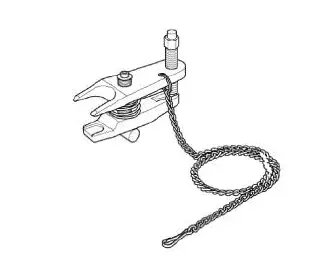
- Ball Joint Remover, 28 mm 07MAC-SL00202
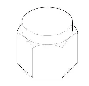
- Ball Joint Thread Protector, 12 mm 07AAF-SDAA100
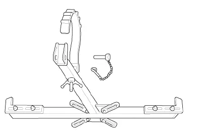
- Subframe Adapter VSB02C000016*
*: Available through the Honda Tool and Equipment Program 888-424-6857.