Rear Knuckle/Hub Bearing Unit Removal and Installation
Exploded View
1. Knuckle/Hub Bearing Unit - Exploded View
Exploded View
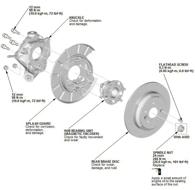
Removal/Installation
NOTE: Refer to the Exploded View as needed during the following procedures.
Hub Bearing Unit
1. Vehicle - Lift
2. Rear Wheel - Remove
3. Parking Brake - Release
4. Brake Caliper - Remove
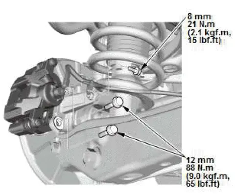
NOTE:
- To prevent damage to the caliper assembly or brake hose, use a short piece of wire to hang the caliper assembly from the undercarriage.
- Do not twist the brake hose excessively.
5. Rear Brake Disc - Remove
6. Rear Spindle Nut - Remove (With AWD)
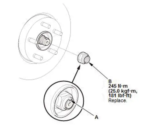
- Pry up the stake (A) on the spindle nut (B).
- Remove the spindle nut.
7. Hub Bearing Unit - Remove
NOTE: Keep the wheel bearing/encoder away from any magnetic field. The encoder can be damaged or erased.

8. Hub Bearing Unit for Damage and Cracks - Check
Knuckle
9. Parking Brake Cable - Disconnect

- Using a flat-tip screwdriver (A), detach the clip (B) and then rotate the clip down.
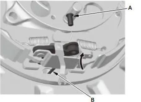
- Pull out the link of the parking brake lever assembly, and then remove the pin (A).
- Remove the parking brake cable (B) from the parking brake lever assembly.
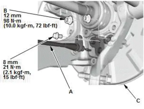
- Remove the parking brake cable (A).
- Remove the flange nuts (B), then remove the backing plate (C) with the parking brake shoe assembly.
10.Parking Brake Assembly - Remove
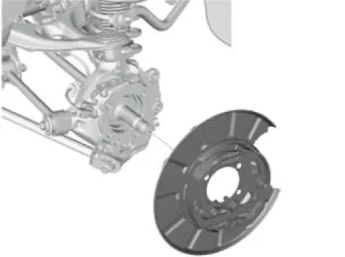
11.Knuckle Items - Remove
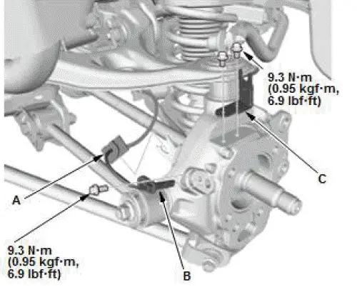
- Remove the wheel speed sensor wire guide rubber (A).
- Remove the wheel speed sensor (B).
NOTE: Do not disconnect the wheel speed sensor connector.
- Remove the brake hose bracket (C).
12.Upper Arm Ball Joint - Disconnect
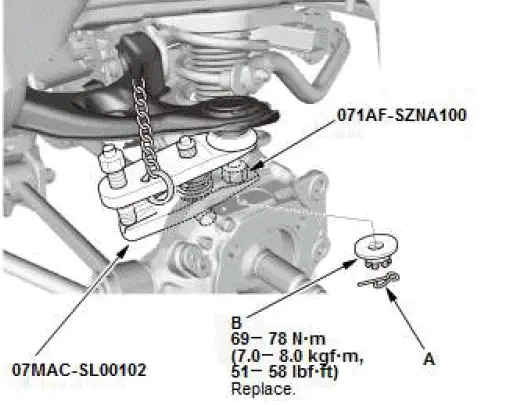
- Remove the lock pin (A).
- Remove the castle nut (B).
- Disconnect the upper arm ball joint from the knuckle using the ball joint thread protector and the ball joint remover.
NOTE: Be careful not to damage the ball joint boot when installing the ball joint remover.
13.Knuckle - Remove

- Remove the control arm (B) mounting self-locking nut (C) and the washer (D).
- Remove the lower arm A mounting bolt (E).

- Remove the flange nut (A) while holding the joint pin (C) with a hex wrench (D).
- Disconnect the stabilizer link (E) from the knuckle (F).
- Remove the lower arm B mounting bolt (G).
- Remove the knuckle.
14.All Removed Parts - Install
- Install the knuckle in the reverse order of removal, and note these items:
- Loosely install nuts and/or bolts to secure the bushings.
Load the suspension with the vehicle's weight and tighten the nuts and/or bolts to the specified torque.
- Be careful not to damage the ball joint boot when connecting the knuckle.
- Before connecting the upper arm ball joint to the knuckle, degrease the threaded section and tapered portion of the ball joint pin, the ball joint connecting hole, the threaded section and mating surfaces of the castle nut.
- Torque the castle nut to the lower torque specification, then tighten it only far enough to align the slot with the ball joint pin hole. Do not align the castle nut by loosening it.
- Before installing the wheel, clean the mating surfaces on the brake disc/drum and the inside of the wheel.
15.Wheel Alignment - Check
Special Tool Required
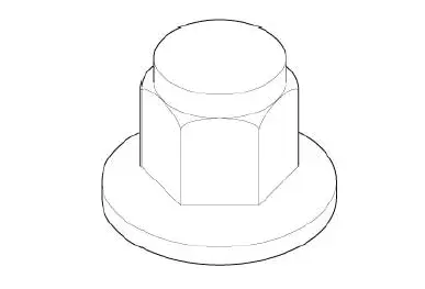
- Ball Joint Thread Protector, 14 mm 071AF-SZNA100
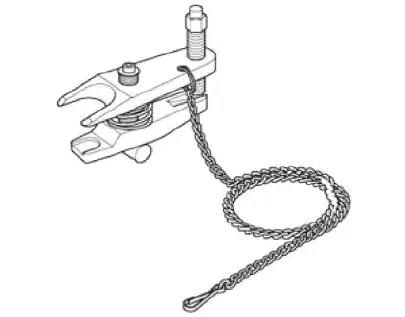
- Ball Joint Remover, 32 mm 07MAC-SL00102