Front Passenger's Power Window Motor Test
Test
Motor Test
1. Front Passenger's Door Panel - Remove
2. Front Passenger's Power Window Motor - Test
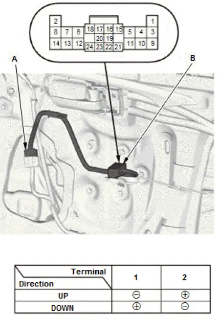
- Connect the connector (A), then install the door panel as needed.
- Test the motor in each direction by connecting 12 volt battery power and ground to the connector (B) according to the table. When the motor stops running, disconnect 12 volt battery power immediately
- If the motor does not run or fails to run smoothly, remove the front passenger's door regulator, then go to step 3.
- If the motor runs smoothly, go to the Hall IC Unit (Pulser) Test.
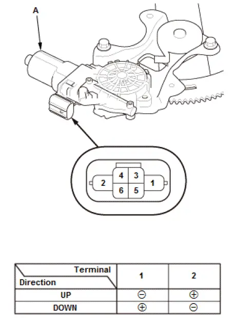
- Test the front passenger's power window motor (A) by connecting 12 volt battery power and ground according to the table. When the motor stops running, disconnect 12 volt battery power immediately.
- If the motor does not run or fails to run smoothly, the front passenger's power window motor is faulty; replace the front passenger's power window motor.
If the motor runs smoothly, troubleshoot the front passenger's power window motor circuit.
Hall IC Unit (Pulser) Test
3. Hall IC Unit (Pulser) - Test

- Remove the front passenger's power window switch.
- Connect the connector (A).
- Turn the vehicle to the ON mode.
- Do the front passenger's power window switch input test terminals No. 21, No. 22, and No. 23.
MTR SVCC circuit

MTR FLSA and MTR FLSB circuits:
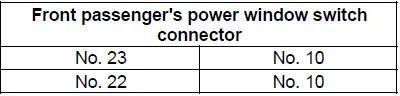
- If the voltage is as specified, replace the front passenger's power window switch (B).
- If the voltage is not specified, the Hall IC Unit (Pulser) is faulty; replace the front passenger's power window motor.
4. All Removed Parts - Install
- Install the parts in the reverse order of removal.
5. Power Window Control Unit - Reset
Front Passenger's Power Window Switch Input Test
NOTE:
- Before testing, make sure the No. C4 (20 A) fuse in the under-dash fuse/relay box is OK.
- Before testing, check for DTCs. If any DTCs are indicated, troubleshoot those DTCs first.
1. Turn the vehicle to the OFF (LOCK) mode.
2. Disconnect the front passenger's power window switch 24P connector.
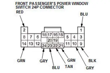
3. Inspect the connector and socket terminals to be sure they are all making good contact:
- If the terminals are bent, loose, or corroded, repair them as necessary, and recheck the system.
- If the terminals are OK, go to step 4.
4. With the connector still disconnected, do the following input tests:
- If any test indicates a problem, find and correct the cause, then recheck the system.
- If all the input tests prove OK, go to step 5.
| Cavity | Wire | Test condition | Test: Desired result | Possible cause if desired result is not obtained |
| 2 - 1 |
RED - BLU |
Connect terminals No. 2 and No. 14, and terminals No. 1 and No. 9 with jumper wires. |
Check front passenger's power window motor operation: The front passenger's power window should close. |
|
| Connect terminals No. 1 and No. 14, and terminals No. 2 and No. 9 with jumper wires. |
Check front passenger's power window motor operation: The front passenger's power window should open. | |||
| 24 | GRY | Disconnect these connectors:
|
Check for continuity between terminal No. 24 and power window master switch 37P connector terminal No. 36: There should be continuity. | An open in the LIN(WINDOW) wire |
| Check for continuity between terminal No. 34 and moonroof motor-control unit 14P connector terminal No. 12: There should be continuity. | An open in the LIN(WINDOW) wire | |||
| Check for continuity to ground: There should be no continuity. | A short to ground in the LIN(P/W) wire |
5. Reconnect the connector, and do the following input tests:
- If any test indicates a problem, find and correct the cause, then recheck the system.
- If all the input tests prove OK, replace the front passenger's power window switch.
NOTE: After replacing the front passenger's power window switch, do the resetting the power window control unit.
| Cavity | Wire | Test condition | Test: Desired result | Possible cause if desired result is not obtained |
| 14 | GRN | Under all conditions | Measure the voltage to ground: There should be battery voltage. |
|
| 9 | BLK | In all power modes | Measure the voltage to ground: There should be less than 0.2 V. |
|
| 21 | GRN | Vehicle ON mode | Measure the voltage to ground: There should be battery voltage. |
|
| 23 | BLU | Vehicle ON mode, and front passenger's power window moving up or down | Measure the voltage between terminals No. 23 and No. 10: An analog meter should alternate between 0 V and 5 V (a digital voltmeter should read about 2.5 V while the window moves). |
|
| 22 | TAN | Vehicle ON mode, and front passenger's power window moving up or down | Measure the voltage between terminals No. 22 and No. 10: An analog meter should alternate between 0 V and 5 V (a digital voltmeter should read about 2.5 V while the window moves). |
|
Fuel and Emissions Systems Symptom Troubleshooting Engine stalls Diagnostic interview
Engine stalls-Diagnostic interview

Engine stalls condition-Possible cause pattern chart from diagnostic interview
| Conditions when the engine stalls | Possible causes | |
| Pattern 1 | Accessories/modifications | ''Hard to start engine'' or ''engine stall'' sometimes occurs due to a fault in the ignition system, intake duct, intake manifold, or exhaust system. (Intermittent failure may occur due to modification) |
| Pattern 2 | Booming noise, vibration occurs when deceleration, stopping, engine stalls | The following intermittent failures may exist.
|
| Pattern 3 | Engine stalls without vibrations as if turning off the ignition switch | The following intermittent failures may exist.
|
Fuel and Emissions Systems Symptom Troubleshooting Hard to start engine Diagnostic interview
Hard to start engine-Diagnostic interview
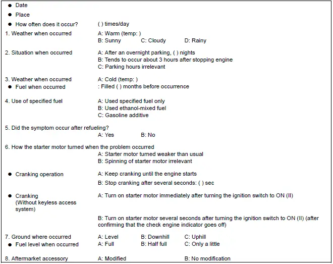
Hard-to start condition-Possible cause pattern chart from diagnostic interview
| Conditions when the engine stalls | Possible causes | |
| Pattern 1 |
|
Check for the EVAP canister purge valve. |
| Pattern 2 | Weather when occurred: Windy | When wind is blowing into the exhaust system, the exhaust gas can blow back into the combustion chamber and/or intake manifold, causing long crank times. |
| Pattern 3 |
|
|
| Pattern 4 |
|
|
| Pattern 5 |
|
|
| Pattern 6 |
|
When the vehicle is parked on an uphill or downhill slope, and the fuel level is low, the fuel pump cannot pickup and pressurize the fuel properly, causing a hard-tostart condition. |
| Pattern 7 |
|
Hard-to-start engine or engine stall may occur due to modified ignition system, intake duct, intake manifold, exhaust system, use of non-specified engine oil or ATF, or excessive amount of engine oil or ATF (temporary failure may occur due to modification). |