Rear Upper Arm Removal and Installation
In this manual: Rear Upper Arm Removal and Installation
5steps
~30min
2/5difficulty
Done 0 of 5
Removal/Installation
1. Vehicle - Lift
2. Rear Wheel - Remove
3. Rear Suspension Stroke Sensor - Disconnect (With Auto Leveling System)
- If removing left side upper arm, disconnect the rear suspension stroke sensor from upper arm.
4. Upper Arm - Remove
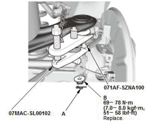
- Remove the lock pin (A).
- Remove the castle nut (B).
NOTE: Use the new castle nut during reassembly.
- Disconnect the upper arm ball joint from the knuckle using the ball joint thread protector and the ball joint remover.
NOTE: Be careful not to damage the ball joint boot when installing the ball joint remover.
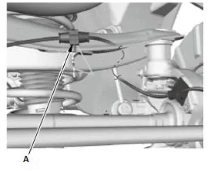
- Remove the wheel speed sensor wire guide rubber (A).
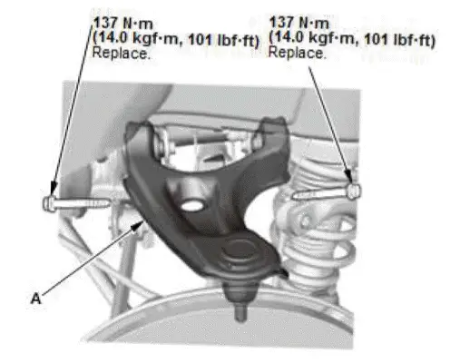
- Remove the upper arm (A).
NOTE: Use the new flange bolts during reassembly.
5. All Removed Parts - Install
- Install the upper arm in the reverse order of removal, and note these items:
- Loosely install nuts and/or bolts to secure the bushings.
Load the suspension with the vehicle's weight and tighten the nuts and/or bolts to the specified torque.
- Be careful not to damage the ball joint boot when connecting the knuckle.
- Before connecting the upper arm ball joint to the knuckle, degrease the threaded section and tapered portion of the ball joint pin, the ball joint connecting hole, the threaded section and mating surfaces of the castle nut.
- Torque the castle nut to the lower torque specification, then tighten it only far enough to align the slot with the ball joint pin hole. Do not align the castle nut by loosening it.
- Before installing the wheel, clean the mating surfaces on the brake disc/drum and the inside of the wheel.
6. Headlight Initial Position - Learn (With Auto Leveling System)
- If removing the upper arm, do the headlight initial position learning procedure.
7. Wheel Alignment - Check
Special Tool Required
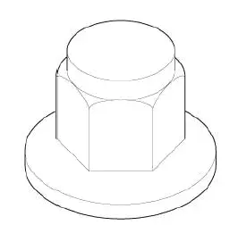
- Ball Joint Thread Protector, 14 mm 071AF-SZNA100

- Ball Joint Remover, 32 mm 07MAC-SL00102
Was this page helpful?